MECHATRONIC DESIGN OF A MODULAR
THREE-AXIS SLIDER SYSTEM FOR
HIGH-PRECISION POSITIONING
APPLICATIONS
a thesis
submitted to the department of mechanical
engineering
and the graduate school of engineering and science
of bilkent university
in partial fulfillment of the requirements
for the degree of
master of science
By
Erva Ulu
August, 2012
I certify that I have read this thesis and that in my opinion it is fully adequate, in scope and in quality, as a thesis for the degree of Master of Science.
Assist. Prof. Dr. Melih C¸ akmak¸cı (Advisor)
I certify that I have read this thesis and that in my opinion it is fully adequate, in scope and in quality, as a thesis for the degree of Master of Science.
Assist. Prof. Dr. Yi˘git Karpat
I certify that I have read this thesis and that in my opinion it is fully adequate, in scope and in quality, as a thesis for the degree of Master of Science.
Prof. Dr. Hitay ¨Ozbay
Approved for the Graduate School of Engineering and Science:
Prof. Dr. Levent Onural Director of the Graduate School
ABSTRACT
MECHATRONIC DESIGN OF A MODULAR
THREE-AXIS SLIDER SYSTEM FOR
HIGH-PRECISION POSITIONING APPLICATIONS
Erva Ulu
M.S. in Mechanical Engineering
Supervisor: Assist. Prof. Dr. Melih C¸ akmak¸cı August, 2012
Following the recent improvements in precision engineering related technol-ogy, interest for micro/nano-engineering applications are increased and various micro/nano-scale operations and products are developed. For micro/nano-scale applications, high-precision equipment including micro/nano-positioning devices with high accuracy and precision are required. In this thesis, mechatronic design of a three axes micro/nano-positioning device is discussed in detail. In order to satisfy nanometer level precision, an adaptive method to increase the available measurement resolution of quadrature encoders is presented.
Performance characteristics of micro/nano-positioning devices usually include positioning accuracy of their each individual axis, operation range, maximum velocity and maximum acceleration. For this reason, permanent magnet linear motors (PMLM) are chosen as actuators in the presented design due to their outstanding characteristics. Moreover, in order to provide high-flexibility in terms of applications and simplify the control of the system, modularity is one of the main concerns while designing the micro/nano-positioning system presented here. Building the modular single axis slider system, three axes positioning device is constructed by assembling three of them perpendicularly. In this design, linear optical encoders are used as feedback sensors. Movement range of the designed system is 120mm in each direction.
Since the available linear optical encoders have measurement resolution of 1µm, resolution of them is to be improved in software for sub-micron level po-sitioning applications. For this purpose, a new method to increase the available measurement resolution of quadrature encoders is presented in this thesis. This method features an adaptive signal correction phase and an interpolation phase.
iv
Imperfections in the encoder signals including amplitude differences, mean offsets and quadrature phase shift errors are corrected by using recursive least squares (RLS) with exponential forgetting and resetting. Interpolation of the corrected signals is accomplished by a quick access look-up table calculated offline to sat-isfy linear mapping from available sinusoidal signals to higher order ones. With the conversion of the high-order sinusoids to binary pulses, position information is derived. By using the presented method, 10nm measurement resolution is achieved with an encoder with 1µm off-the-shelf resolution. Experiment results demonstrating the effectiveness of the proposed method are presented. Valida-tion of the method is accomplished for several cases including the best resoluValida-tion obtained. Practical constraints limiting the maximum interpolation number are also discussed in detail.
Keywords: Precision positioning, encoder resolution, adaptive systems, measure-ment interpolation, quadrature encoder signals, modular design.
¨
OZET
Y ¨
UKSEK HASSAS˙IYETL˙I POZ˙ISYONLAMA
UYGULAMALARI ˙IC
¸ ˙IN MOD ¨
ULER ¨
UC
¸ -EKSENL˙I
KIZAK S˙ISTEM˙IN˙IN MEKATRON˙IK TASARIMI
Erva Ulu
Makine M¨uhendisli˘gi, Y¨uksek Lisans
Tez Y¨oneticisi: Assist. Prof. Dr. Melih C¸ akmak¸cı A˘gustos, 2012
Hassas m¨uhendislik alanındaki teknolojik ilerlemeyi takiben mikro/nano-m¨uhendislik uygulamalarına olan ilgi artmı¸s, son yıllarda mikro/nano-boyutlu bir¸cok s¨ure¸c ve ¨ur¨un geli¸stirilmi¸stir. Mikro/nano boyutlarda i¸slem yapabilmek i¸cin kullanılacak makinaların y¨uksek do˘gruluk ve hassasiyete sahip mikro/nano-pozisyonlama cihazları i¸cermesi gerekmektedir. Bu tezde bir ¨u¸c eksenli mikro/nano-pozisyonlama cihazının mekatronik tasarımı detaylı bir bi¸cimde an-latılmaktadır. Ayrıca, nanometre seviyesinde hassasiyet de˘gerlerine ula¸sabilmek i¸cin d¨ort evreli enkoderlerin mevcut ¸c¨oz¨un¨url¨uk de˘gerlerinin arttırılmasını sa˘glayan uyarlamalı bir metod sunulmaktadır.
Mikro/nano-pozisyonlama cihazlarının performans karakteristi˘gi genellikle ek-senlerin konumlama hassasiyetleri, hareket aralı˘gı, maksimum hız ve ivmelen-meleri olmaktadır. Bu sebeple, bu tezde bahsedilen tasarımda eyleyici olarak ¨
ust¨un karakteristiklerinden dolayı s¨urekli mıknatıs lineer motorlar (PMLM) se¸cilmi¸stir. Ayrıca, kullanıcıya uygulamalarda esneklik sa˘glaması ve sistem kontrol¨un¨u kolayla¸stırması amacıyla burada sunulan mikro/nano-pozisyonlama sisteminin tasarımı yapılırken mod¨ulerite ana kriterler arasında tutulmu¸stur. Mod¨uler tek eksenli kızak sisteminin tasarımından sonra bu kızaklardan ¨u¸c tanesinin birbirine dik olarak montajı ile ¨u¸c eksenli pozisyonlama cihazı olu¸sturulmu¸stur. Bu tasarımda geri besleme sens¨or¨u olarak lineer optik enkoder-ler kullanılmı¸stır. Geli¸stirilen sistemin hareket aralı˘gı her eksende 120mm’dir.
Mevcut lineer optik enkoderlerin ¨ol¸c¨um ¸c¨oz¨un¨url¨ukleri 1µm oldu˘gundan mikron altı seviyelerdeki pozisyonlama uygulamaları i¸cin enkoderlerin ¸c¨oz¨un¨url¨ukleri yazılım ¨uzerinde arttırılmalıdır. Bu ama¸cla, d¨ort evreli enkoderlerin mevcut
vi
¸c¨oz¨un¨url¨uklerini arttırmak ¨uzere geli¸stirilen yeni bir metod bu tezde sunulmak-tadır. Bu metod uyarlamalı sinyal d¨uzeltme ve interpolasyon a¸samalarından olu¸smaktadır. Enkoder sinyallerindeki b¨uy¨ukl¨uk farkları, ortalama de˘ger sap-maları ve d¨ort evreli faz farkı hataları ¨ussel unutmalı ve sıfırlamalı tekrarla-malı en k¨u¸c¨uk kareler y¨ontemi (RLS) kullanılarak d¨uzeltilmektedir. D¨uzeltilmi¸s sinyallerin interpolasyonu ise ¸cevrim dı¸sı olu¸sturulmu¸s bir hızlı eri¸simli tara-malı tablo sayesinde yapılmaktadır. Bu tablo ile orijinal enkoder sinyalleri ile y¨uksek dereceli sin¨uzoidler arasında do˘grusal e¸sle¸stirme yapılmı¸stır. Y¨uksek dereceli sin¨uzoidlerin ikili pulslara d¨on¨u¸st¨ur¨ulmesi sonucunda pozisyon bilgisi elde edilmi¸s olur. Sunulan metod kullanılarak 1µm orijinal ¸c¨oz¨un¨url¨u˘g¨u olan bir enkoder ile 10nm’lik ¨ol¸c¨um ¸c¨oz¨un¨url¨u˘g¨u elde edilmi¸stir. ¨Onerilen metodun etkinli˘gini g¨osteren deneyler tez i¸cerisinde verilmi¸stir. Metodun do˘grulaması elde edilen en y¨uksek ¸c¨oz¨un¨url¨uk dahil olmak ¨uzere ¸ce¸sitli ¸c¨oz¨un¨url¨uk de˘gerleri i¸cin ba¸sarıyla yapılmı¸stır. Maksimum interpolasyon sayısını sınırlandıran pratikteki kısıtlamalar da detaylıca incelenmi¸stir.
Anahtar s¨ozc¨ukler : Hassas pozisyonlama, enkoder hassasiyeti, uyarlamalı sistem-ler, ¨ol¸c¨um arade˘gerlemesi, d¨ort evreli enkoder sinyalleri, mod¨uler dizayn.
Acknowledgement
I would like to thank my advisor, Assist. Prof. Melih C¸ akmakcı. His guidance, support and encouragement have been crucial to my successful completion of all the work contained in this thesis.
I would also like to thank Assist. Prof. Sinan Filiz for his valuable advice and help throughout this study.
I wish to give my thanks to members of Bilkent University Mechanical Engi-neering Department and the thesis committee.
I would also acknowledge the help of the undergraduate students working in our lab, Ersun Sozen and Oytun Ugurel.
I would also like to thank The Scientific and Technology Research Council of Turkey (T ¨UB˙ITAK) for the support of this research through grants and I am also grateful to T ¨UB˙ITAK for National Scholarship for Master of Science Students (T ¨UB˙ITAK - 2210 Yurt ˙I¸ci Y¨uksek Lisans Bursu).
I am also thankful to my family and friends for their love, support and en-couragement.
Lastly, but most importantly I would like to express my special thanks to my wife, Nurcan Ge¸cer Ulu.
Contents
1 Introduction 1
2 Background Information 5
2.1 Micro/Nano-Positioning Systems . . . 5
2.2 Encoder Resolution Improvement Methods . . . 8
3 Design of Micro/Nano-Positioning Device 12 3.1 Modular Single-Axis Slider System . . . 12
3.1.1 Components and Control Setup . . . 14
3.1.2 Design Improvements of Mechanical Components . . . 18
3.2 Assembly Configurations of Modular Slider . . . 24
3.3 Three-Axis Slider System . . . 26
3.3.1 Counter Balance Subsystem . . . 26
3.3.2 Manufacturing and Assembly Tolerances . . . 28
CONTENTS ix
4.1 Overview of the Proposed Approach . . . 32
4.2 Adaptive Encoder Signal Correction (Step 1) . . . 35
4.3 Look-up Table Based Signal Interpolation (Step 2) . . . 40
4.4 Binary Pulse Generation and Position Information . . . 46
4.5 Practical Limitations . . . 48
5 Real-Time Implementation 50 5.1 Real-Time Implementation of Encoder Resolution Improvement Method . . . 51
5.2 Real-Time Implementation of Overall Control System . . . 55
6 Validation and Experiments 58 6.1 Validation of Encoder Resolution Improvement Method . . . 59
6.1.1 Experimental Setup . . . 59
6.1.2 Validation Test Results . . . 61
6.2 Experimental Results . . . 65
7 Conclusion and Future Works 73
List of Figures
1.1 Closed Loop System Setup of a Typical Positioning Device . . . . 2
2.1 Ballscrew Mechanism [1] . . . 6
2.2 Piezoelectric Actuator [2] . . . 7
2.3 Permanent Magnet Linear Motor [3] . . . 8
2.4 Ideal and Interpolated Encoder Signals . . . 9
2.5 Exaggerated Illustration of Original Encoder Signals . . . 10
3.1 3D Drawing of Three-Axis Positioning System . . . 13
3.2 3D Drawing of Single-Axis Slider . . . 13
3.3 Top View of the Designed Single Axis Slider . . . 14
3.4 Bottom View of the Designed Single Axis Slider . . . 15
3.5 Single Axis Slider with its Components . . . 17
3.6 Closed Loop Control System Setup of the Single Axis Slider . . . 17
LIST OF FIGURES xi
3.8 (a) Top and (b) Bottom View of the Previous Single Axis Slider
Design . . . 19
3.9 Moving Sliders and Stationary Bottom Bases of (a) Previous and (b) New Single Axis Slider Designs . . . 20
3.10 (a) Previous and (b) New Scale Holder Designs . . . 21
3.11 Safety Pins on Encoder Scale Holder . . . 22
3.12 Single Axis Slider . . . 22
3.13 Example Single Axis Assembly Configurations with a One, (b) Two and (c) Three Sliders . . . 23
3.14 Example Two Axis Assembly Configurations Using Two Sliders in a X-Y (b) Oblique X-Y and (c) X-Z Arrangements . . . 23
3.15 Example Two Axis Assembly Configurations Using Three Sliders in a X-Y (b) Oblique X-Y and (c) X-Z Arrangements . . . 24
3.16 Example Three Axis Assembly Configurations Using Three Sliders in a X-Y-Z (b) Oblique X-Y-Z Arrangements . . . 25
3.17 Two Axis Slider System . . . 26
3.18 Three Axis Micro/Nano-Positioning System . . . 27
3.19 Counter Balance Subsystem . . . 28
3.20 (a) Tolerance Critical Sections of Single Axis Slider with Detail Views of (b) Section A and (c) Section B . . . 29
4.1 General Flow Diagram of the Proposed Approach . . . 33
4.2 Encoder Signal Parameters Recorded Through 120mm Motion of the Single Axis Slider . . . 38
LIST OF FIGURES xii
4.3 Corrected Encoder Signals Using RLS (a) with and (b) without
Resetting . . . 39
4.4 Corrected and Original Encoder Signals . . . 40
4.5 Verification of Quadrature Phase Difference Between Corrected Signals . . . 41
4.6 Interpolation Results for n = 25 . . . 45
4.7 Variation of Index Number for n = 25 . . . 45
4.8 Binary Pulses Obtained for n = 25 . . . 47
4.9 Example Showing Encoder Signals and Binary Pulses for (a) With-out Interpolation (b) With Interpolation Cases . . . 48
5.1 Encoder Resolution Improvement Method Labview Implementation 51 5.2 Encoder Signal Correction Labview Implementation . . . 52
5.3 Look-up Table Based Interpolation Labview Implementation . . . 54
5.4 Binary Pulse Generation and Position Information Derivation Lab-view Implementation . . . 55
5.5 Labview Implementation of Overall Control System for Single Axis Slider System . . . 56
5.6 Labview Implementation of Control Loop for Single Axis Slider System . . . 56
6.1 Testbed for Validation Experiments . . . 60
6.2 Validation Results on x-Axis Slider for Interpolation Number of n = 10 Resulting 100nm Measurement Resolution . . . 62
LIST OF FIGURES xiii
6.3 Validation Results on x-Axis Slider for Interpolation Number of
n = 50 Resulting 20nm Measurement Resolution . . . 62
6.4 Validation Results on x-Axis Slider for Interpolation Number of n = 100 Resulting 10nm Measurement Resolution . . . 62
6.5 Validation Results on y-Axis Slider for Interpolation Number of n = 10 Resulting 100nm Measurement Resolution . . . 63
6.6 Validation Results on y-Axis Slider for Interpolation Number of n = 50 Resulting 20nm Measurement Resolution . . . 63
6.7 Validation Results on y-Axis Slider for Interpolation Number of n = 100 Resulting 10nm Measurement Resolution . . . 63
6.8 Validation Results on z-Axis Slider for Interpolation Number of n = 10 Resulting 100nm Measurement Resolution . . . 64
6.9 Validation Results on z-Axis Slider for Interpolation Number of n = 50 Resulting 20nm Measurement Resolution . . . 64
6.10 Validation Results on z-Axis Slider for Interpolation Number of n = 100 Resulting 10nm Measurement Resolution . . . 64
6.11 Interpolation Results for n = 16 . . . 66
6.12 Interpolation Results for n = 50 . . . 66
6.13 Interpolation Results for n = 100 . . . 67
6.14 Tracking Performance of the Single Axis Slider . . . 67
6.15 Reference Input Trajectory for Two-Axis Slider System . . . 68
6.16 Tracking, (a) and (b), and Contouring, (c), Performance of Two-Axis Positioning System . . . 69
LIST OF FIGURES xiv
6.17 Three Dimensional Reference Input Trajectory for Three-Axis Slider System . . . 70 6.18 Tracking, (a), (b)and (c), and Contouring, (c), Performance of
Three-Axis Positioning System . . . 72
A.1 Labview Front Panel for Single Axis Slider . . . 80 A.2 Labview Front Panel for Two-Axis Slider System . . . 81 A.3 Labview Implementation of Overall Control System for Two-Axis
Slider System . . . 82 A.4 Labview Front Panel for Three-Axis Slider System . . . 83 A.5 Labview Implementation of Overall Control System for Three-Axis
List of Tables
3.1 Specifications of BLMUC-95 Linear Motor . . . 16
4.1 A Generic Look-up Table . . . 42 4.2 Index Calculation Table . . . 44
Chapter 1
Introduction
There is a growing interest for precision positioning systems from various micro/nano-technology applications [4]. Micro/nano manufacturing and assem-bly, optical component alignment systems, scanning microscopy applications, nano-particle placement applications, biotechnology applications and cell/tissue engineering are some examples of the applications that precision positioning de-vices are commonly used [5, 6, 7]. High precision positioning dede-vices are required for any operations in micro/nano-scale applications. Performance characteristics of these devices depend on positioning accuracy, maximum velocity and accelera-tion that they can operate with acceptable performance based on the applicaaccelera-tion. These characteristics are mostly determined by the actuator that gives motion to the slider and the feedback sensor that supplies the position information.
Commonly used actuators for micro/nano-positioning systems are piezoelec-tric actuators [8, 9, 10], ballscrew mechanisms [5, 11] and permanent magnet linear motors (PMLM) [11, 12]. Piezoelectric actuators have the motion range of just tens of micrometers and they are limited in terms of acceleration and velocity capabilities [5]. Also, for a ballscrew mechanism, a ballscrew is coupled with a DC motor to convert the motor rotary motion into linear motion. Thus, ballscrew driven mechanisms have accuracy limitations due to backlash and wear of the mechanical components, and their acceleration and velocity capabilities are limited as a result of the ballscrew mechanism [12]. On the other hand, linear
Amplifier Output Input Controller Motor Encoder
Figure 1.1: Closed Loop System Setup of a Typical Positioning Device motors are gaining popularity for precision positioning applications due to their superior characteristics. Due to their designs, there is no contact between the stationary and moving parts of PMLMs. Hence, backlash or wear is not concern and nonlinearity due to the contact mechanism is also eliminated. With the lin-ear motors, high acceleration and velocity values can be achieved in long ranges (greater than 100mm).
As feedback sensors, high-resolution sensors are required in micro/nano-positioning systems in order to satisfy high-precision. Commonly used sensors are laser interferometers, capacitive sensors and optical encoders [12, 13]. Although laser interferometers and capacitive sensors can reach up to sub-nanometer level measurement resolutions, their sensing range is limited to micrometer level [14, 13]. Conversely, measurement ranges of linear optical encoders are higher (hundreds of milimeters) but their resolutions are usually in micrometer level [15].
In this thesis, the main objective is to design a three-axis micro/nano-positioning device that can operate in long ranges (120mm x 120mm x 120mm). Due to their outstanding characteristics PMLM is used as the actuator in single axis slider design. Moreover, linear optical encoders are used as feedback sensors since their measurement range is suitable for the desired system. For the design process, modularity is one of the main concerns in order to provide high flexibility in terms of applications and simplify the control of the system. For this purpose, the three-axis positioning system is designed as combination of modular single-axis sliders. With the modular design, range of the possible applications can be
increased with adjustable operation spaces. Several example assembly configu-rations of modular single axis sliders are supplied. For the cases with vertical slider arrangement including the three-axis positioning system presented in this thesis, a counter balance subsystem is presented. Design processes of mechanical components of the three-axis slider system is explained.
Closed loop system setup illustration of a typical positioning device is given in Figure 1.1. As it can be observed from this figure, performance characteristics of positioning devices depend highly on the precision and resolution that can be obtained from the encoders. Yet, achievable resolution with decreasing the pitch of scale grating is limited by the available manufacturing technologies used for the optical encoders [16, 17]. For example, with the current available manufac-turing technologies, commercially available linear optical encoders can have 0.512 micrometers scale grating in pitch satisfying 0.128 micrometers of optical reso-lution. Hence, in order to achieve high performance with the overall positioning system, it is crucial to increase the resolution of the encoders. Signal processing techniques for interpolation of the available encoder signals serves further im-provement of the encoder resolution by deriving intermediate position values out of the original sinusoidal encoder signals.
In this thesis, a new adaptive approach to obtain high-resolution position in-formation using the original encoder signals is presented. Our motivation here is to generate high-order quadrature sinusoids from the original encoder signals so that any deviations or distortions in these signals can be tolerated. Moreover, the approach is to be suitable for modular sliders in such a manner that appli-cation of the method on different encoders do not require any modifiappli-cations in the algorithm. For this purpose, an adaptive signal conditioning step to obtain ideal sinusoids with quadrature phase difference is applied before the interpo-lation process. Then, mapping of the first-order signals to higher-order ones is accomplished by a quick-access look-up table. This table is generated offline by using the mathematical values of high-order sinusoids to increase the flexibility of the method for the application on modular slider systems. With the conversion of the high-order sinusoids to binary pulses, high-resolution position information is obtained. External validation of the presented encoder resolution improvement
method is accomplished using a laser vibrometer with known measurement res-olution. Moreover, practical constraints limiting the application of the method is discussed. Performance of the method is examined by various experiments conducted on single, two and three axis positioning systems.
The remainder of this thesis is organized as follows. In Chapter 2, background information and previous works in the literature on high-precision positioning sys-tem design and encoder resolution improvement methods are reviewed. Chapter 3 presents design processes of the modular single-axis micro/nano-positioning de-vice. Then, a specific three-axis configuration of single axis sliders is introduced. Chapter 4 proposes a new adaptive approach to obtain high-resolution position information out of the original encoder signals. Proposed signal correction and interpolation methods are discussed. Chapter 5 provides detailed information about the real-time implementation of encoder resolution improvement method using the Labview programming environment. In Chapter 6, validation of the encoder resolution improvement method is performed. Experiment results on the new method is also presented in this chapter. Effects of the presented method on positioning performance is examined. Conclusions and future work are discussed in Chapter 7.
Chapter 2
Background Information
In this thesis, development of a three axes high-precision positioning system and an encoder resolution improvement method proposed for this system is discussed. This chapter reviews the background information and previous work in these areas. For this purpose, firstly, current technologies on micro/nano-positioning systems is presented. Then, basic idea behind the encoder resolution improvement methods is explained and literature survey on this subject is introduced.
2.1
Micro/Nano-Positioning Systems
Micro/nano-scale applications require micro/nano-positioning devices with high precision and accuracy. High precision positioning devices are generally con-structed as assembly of separately manufactured single axis slider systems [7, 5, 6]. Performance characteristics of these systems depend on positioning accuracy, maximum velocity and maximum acceleration that they can operate with ac-ceptable performance based on the application. These characteristics are mostly determined by the actuator that gives motion to the slider. There is a strong rela-tionship between properties of the actuator used and performance of the position-ing system. Commonly used actuator types for positionposition-ing devices are ballscrew mechanisms [5, 11], piezoelectric actuators [8, 9, 10] and permanent magnet linear
DC Motor
Ballscrew
Moving Slider
Figure 2.1: Ballscrew Mechanism [1] motors [11, 18, 19, 20, 21, 12].
Ballscrew driven linear actuators are powered by a DC-motor and they can operate in long ranges. In these systems, a ballscrew is coupled with a DC-motor to convert the motor rotary motion into linear motion. An example ballscrew mechanism is given in Figure 2.1 showing the components of the system. As mentioned in literature, ballscrew mechanism driven linear stages have accuracy limitations due to backlash and wear of the mechanical components, and their acceleration and velocity capabilities are limited as a result of the ballscrew mech-anism [19, 20, 22, 23, 24]. In this type of linear stages, one of the commonly used methods to calculate displacement of the slider is that angular position of the motor is measured and this measurement is simply multiplied by the pitch of the ballscrew. Due to the wear of the mechanical components in time, position, ve-locity and acceleration measurements obtained using this indirect measurement method may not be reliable [4, 5, 19].
Piezoelectric actuator (Figure 2.2) is another commonly used actuator type in precision positioning devices. Ceramic piezoelectric actuators convert volt-age into displacement. Piezoelectric stvolt-age design includes flexures deflected by piezoelectric actuators. Although high accuracy and high precision values can be reached with piezoelectric stages, they cannot be used in many applications since they have limited work-space (less than 1 mm in each direction) and limited
Figure 2.2: Piezoelectric Actuator [2] acceleration/velocity response [8, 4, 25].
With the recent commercial introduction of the linear motors, linear motor driven stages have been gaining popularity in precision engineering applications due to their superior characteristics [26]. A linear motor is an actuator that operates on a flat plane. Similar to working principle of DC motor, a linear motor converts electromagnetic force into mechanical motion. A linear motor is made of a coil and a magnet rail as shown in Figure 2.3. When current is applied on the coil, the magnetic force moves the motor on the magnet rail. The coil does not touch the magnet rail so that backlash or wear is not a concern. Moreover, nonlinearity due to contact mechanism is eliminated. Since linear motor driven stages do not require ballscrews, high acceleration and velocity values can be achieved [11, 27]. Furthermore, permanent magnet linear motors can operate in long ranges (typically greater than ten centimeters) compared to the piezoelectric motors. Position is measured directly on the stage with a linear encoder making the positioning extremely reliable. However, there are nonlinear disturbances in a permanent magnet linear motor due to force ripples that are caused by imperfections in the underlying components. These nonlinearities can be compensated through various control methods [18].
Another important component affecting the performance of a micro/nano-positioning device is the feedback sensor that supplies the position, velocity and acceleration information to the system. As feedback sensors, high-resolution sen-sors are used in micro/nano-positioning systems in order to satisfy high-precision.
Motor Core
Magnet Rail
Figure 2.3: Permanent Magnet Linear Motor [3]
For this purpose, commonly used sensors are laser interferometers, capacitive sen-sors and optical encoders [12, 16, 17, 13]. Commercially available laser interfer-ometers and capacitive sensors can reach up to sub-nanometer level measurement resolutions [28, 14]. However, their sensing range is very limited (usually smaller than one milimeter) [28, 14, 13]. On the other hand, measurement ranges of linear optical encoders may be around hundreds of milimeters. Yet, their resolutions are limited to micrometer level [15]. Maximum resolution value of a commer-cially available linear optical encoders is 0.128µm due to current manufacturing technologies. Hovewer, using signal processing techniques for interpolation of available encoder signals, nanometer level resolution can be obtained with linear optical encoders [16, 17, 29, 30]. Hence, linear optical encoders are advantageous over laser interferometers and capacitive sensors when long range of motion is main focus of interest.
2.2
Encoder Resolution Improvement Methods
As mentioned previously, precision and resolution of feedback sensor in the system have significant influence on performance characteristics of micro/nano-positioning devices. Therefore, it is important to have high resolution feedback sensors to obtain high positioning performance. However, available manufactur-ing technologies allow only micrometer level of scale gratmanufactur-ing for linear optical encoders (i.e. maximum 0.128µm optical resolution). Hence, further improve-ment in resolution of optical encoders is only possible with signal processing
0 180 360 540 720 900 −1.5 −1 −0.5 0 0.5 1 1.5 Angle [Degree] Amplitude [V] u 1i and u2i u1n and u2n
Figure 2.4: Ideal and Interpolated Encoder Signals
techniques. In order to increase the available resolution of an optical encoder, encoder signals should be interpolated to reach intermediate position values.
Basic idea behind an interpolation method is that high order sinusoidal sig-nals can be generated from original first order analog encoder sigsig-nals by using a suitable mapping function between them. Converting the calculated high order sinusoids to binary pulses and counting the zero-crossings, intermediate position information can be obtained. In Figure 2.4, an example interpolated signal pair is given with the ideal encoder signals to demonstrate the basic idea of an inter-polation method. In this figure, u1n and u2n are high order signals (10th order for
this case) obtained as a result of interpolation process and u1i and u2i are ideal
quadrature encoder signals.
Although it is possible to achieve high resolution values using various kinds of interpolation techniques, both hardware and software interpolation methods require ideal encoder signals with a quadrature phase difference between them. However, the encoder signals usually contain some noise and errors due to en-coder scale manufacturing tolerances, assembly problems, operation environment conditions, and electrical grounding problems. Interpolation errors occur while
0 180 360 540 720 900 1080 1260 1440 1620 1800 −1.5 −1 −0.5 0 0.5 1 1.5 Angle [Degree] Amplitude [V] m 2 m 1 90+φ A 2 A1 u 2 u1
Figure 2.5: Exaggerated Illustration of Original Encoder Signals
extracting intermediate position information from the distorted pair of sinusoidal encoder signals. Therefore, these errors and noises have to be compensated before the interpolation method is applied. Common errors affecting the quadrature en-coder signals are amplitude difference, mean offsets, and quadrature phase shift errors. In Figure 2.5, an exaggerated illustration of these errors are shown on an encoder signal pair, u1 and u2. In this figure, mean offsets are denoted as m1
and m2, amplitudes are A1 and A2 and φ is the phase shift error. For an ideal
encoder signal pair, values of m1 and m2 should be 0V , A1 and A2 should be 1V
and φ should be 0degree. Hence, the basic idea behind a correction method is to compensate these errors using mathematical relationship between distorted and ideal signal pair.
So far, many different approaches have been developed to correct the distorted encoder signals containing amplitude errors, mean offsets, and quadrature phase shift errors. The first introduced method was proposed by Heydemann [31]. In this method, errors in the encoder signal pairs are determined effectively using least squares minimization. Then, correction is done based on the calculated error values. Since the correction parameters are calculated offline, this method does not offer an effective compensation when the errors are changing dynamically
throughout the motion. Applications of this correction method can be found in [16] and [30]. In order to compensate the dynamic errors in encoder signals, several online compensation methods are developed. In [32], Balemi used gradient search method to calculate the correction parameters online, but performance of this method is not effective in low frequencies and noisy signals as mentioned in [33]. Another online error compensation method proposed in [17] corrects the sinusoidal signals obtained from a linear optical encoder by making use of an adaptive approach based on radial basis functions neural network. Then, authors use the similar procedure to increase the resolution of the encoder by mapping the original encoder signals to high-order sinusoids using another set of radial basis functions. Although high-resolutions can be achieved with this method, it requires a training period for every new encoder. Also, changes in the environmental conditions may require a new training period. Other interpolation methods also exist. In [34], Cheung proposed a sine-cosine interpolation method using logic gates and comparators. In [35], interpolation of encoder signals is accomplished by using digital signal processing (DSP) algorithms followed by digitization of sinusoidal encoder signals with analog-to digital converters (ADC). However, these interpolation approaches require external hardware such as high precision ADCs and DSPs to obtain high resolution from the encoder. Hence, their applicability to typical servo controllers with a digital incremental encoder interface is limited [17]. Another interpolation approach used so far is based on look-up tables. Tan et al. [16] obtained high-order sinusoids from original encoder signals using mathematical relationship between them. Then, they stored the values of high-order sinusoids in a look-up table. Using this table for online mapping of original encoder signals to higher-order ones, they managed to achieve intermediate position values leading high resolution values. Some other hardware and software based interpolation methods are also applied on magnetic encoders and resolver sensors [33, 36, 37].
Chapter 3
Design of
Micro/Nano-Positioning Device
In this thesis, a specific design of a three-axis micro/nano-positioning device with 120mm x 120mm x 120mm operation space is the main focus of interest. However, this device is constructed by using three of the same modular single axis sliders perpendicular to each other. In this chapter, first, design of the modular single axis slider system is discussed in detail with its components and closed loop control setup. Improvements made on mechanical components during the design process of single axis slider are also summarized. Next, possible assembly configurations of designed modular single axis sliders are examined. Then, the specific three-axis configuration of sliders is introduced including the counter balance system, manufacturing and assembly tolerances of the system.
3.1
Modular Single-Axis Slider System
Our three-axis positioning system will be composed of three modular single axis stages assembled perpendicularly as shown in Figure 3.1. As a first step to de-velop this system, a modular linear slider that can achieve micro/nano-meter level positioning over 120mm operation range is built. In Figure 3.2, a 3D model
Figure 3.1: 3D Drawing of Three-Axis Positioning System
of designed single axis linear slider is given. While designing this slider sys-tem, components are chosen elaborately to accomplish their specific purpose for micro/nano-positioning tasks. In this section, mechanical and electrical compo-nents of the single axis slider system is given. Control setup of the closed loop system is also introduced. Then, details of design improvements of mechanical components are explained with reasoning.
3.1.1
Components and Control Setup
Performance of a micro/nano positioning device can be evaluated by its working range, maximum velocity and acceleration, positioning resolution and positioning accuracy values. Components of the single axis slider presented in this thesis are chosen considering these performance characteristics. Moreover, modularity is another concern while designing the mechanical components of the slider.
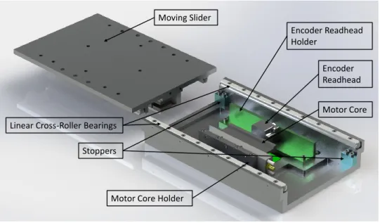
As illustrated in Figure 3.3 and Figure 3.4, modular single axis slider is de-signed with a stationary base and a moving slider that are connected to each other via cross-roller linear bearings from THK. The stage is actuated by a brushless permanent magnet linear motor from Aerotech Inc. (BLMUC-95 and MTUC-224) whereas the position feedback is taken from an optical linear incremental encoder from Heidenhain Corp. (LIP 481R). In addition to linear motor, opti-cal encoder and linear bearings, eight mechaniopti-cal components are designed and manufactured for the modular single axis slider.
Moving Slider
Linear Cross-Roller Bearings Stoppers
Motor Core Holder
Motor Core Encoder Readhead Encoder Readhead Holder
Figure 3.3: Top View of the Designed Single Axis Slider
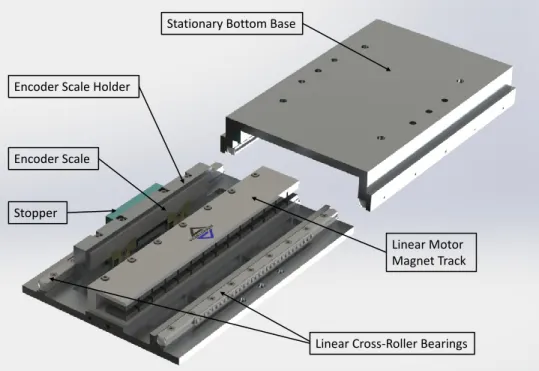
In design of the single axis slider, linear bearings are chosen to satisfy linear motion of the sliding part with minimum friction. Cross-roller bearings are used to carry both vertical and horizontal loads effectively. In order to satisfy high
Linear Cross-Roller Bearings Stationary Bottom Base
Stopper
Linear Motor Magnet Track Encoder Scale
Encoder Scale Holder
Figure 3.4: Bottom View of the Designed Single Axis Slider
precision motion, VR model low-friction, high-accuracy, precision roller bearings [38] are preferred.
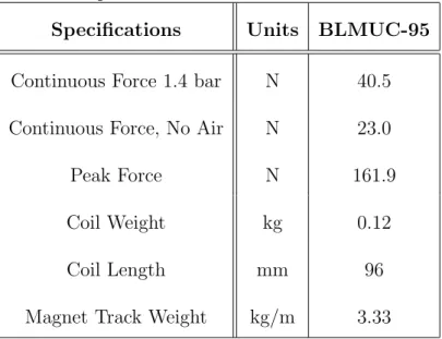
As the actuator, permanent magnet linear motor is chosen due to its out-standing characteristics in precision positioning applications. The most impor-tant feature of this type of actuator is that long ranges (more than 100mm) can be traveled with high velocity and acceleration. The chosen linear motor, BLMUC-95, is a very compact linear motor with 52.0mm x 20.8mm cross section and 224mm track length. This feature makes it suitable for compact systems. In or-der to satisfy desired 120mm motion, track length is chosen as 224mm since linear motors can operate effectively only when the motor coil is inside of the magnet track completely. As mentioned in [3], backlash, windup, wear and maintenance issues associated with ball screws, belts, and rack and pinions are eliminated by non-contact design of the motor. Moreover, more than 25N force can be gener-ated by this motor. Some important specifications of the linear motor used in the single axis slider system is given in Table 3.1.
Table 3.1: Specifications of BLMUC-95 Linear Motor Specifications Units BLMUC-95 Continuous Force 1.4 bar N 40.5 Continuous Force, No Air N 23.0 Peak Force N 161.9 Coil Weight kg 0.12 Coil Length mm 96 Magnet Track Weight kg/m 3.33
an optical linear incremental encoder (LIP 481R) so that positioning measure-ments become extremely reliable. This encoder has 4µm scale grating in pitch satisfying 1µm original measurement resolution. However, this resolution is in-creased up to 10nm using a new encoder interpolation technique presented in Chapter 4. As described in [15], the readhead and scale of the optical encoder are assembled on the system so that the distance between them is approximately 0.6mm for effective measurements with low noise levels. In order to satisfy this assembly requirement, a specific plastic sheet with 0.6mm thickness is placed between the readhead and the scale so that mounting screws can be tighten in correct positions.
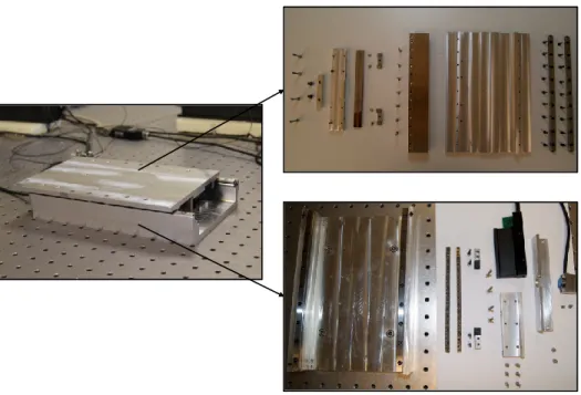
As mentioned previously, eight mechanical components are designed and man-ufactured for the single axis slider. These parts are stationary bottom base, mov-ing slider, stopper parts, motor core holder, encoder readhead holder and encoder scale holder. All of these parts can be seen in Figure 3.3 and Figure 3.4. While designing these parts, the main concerns are ease of assembly, modularity and compactness. Moreover, geometrical properties of these parts are designed to keep their rigidity during the manufacturing processes. For modularity purposes, each part is designed so that a single axis slider can be assembled on another one in various configurations to build single, two or three axis systems for different
Figure 3.5: Single Axis Slider with its Components
applications. Here, any of the configurations can be built without making any modifications in the single axis slider. In Figure 3.5, designed single axis slider is given with all of its components.
Amplifier+
Linear Motor Slider
Optical Encoder Desired Position Actual Position PLANT Control Algorithm Analog Input Analog Output Interpolation Algorithm CONTROLLER Command Voltage Encoder Signals Axial Force u1, u2 Position
Figure 3.6: Closed Loop Control System Setup of the Single Axis Slider In addition to a suitable mechanical design for micro/nano-positioning appli-cations, an appropriate control setup is required to control the single axis slider system with high precision. Closed loop configuration of the control system for
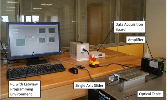
Single Axis Slider Amplifier Optical Table Data Acquisition Board PC with Labview Programming Environment
Figure 3.7: Photograph of Testbed for the Single Axis Slider
single axis slider is given in Figure 3.6. As it is shown in this figure, a controller and an amplifier is required in the control system. In our system, control algo-rithm is developed on a PC using NI Labview programming environment. Several control schemes are used to control the system including the basic PID control and more complex control techniques such as iterative learning [39], model ref-erence adaptive control. A standard current commanded six-point commutation amplifier from Aerotech Inc. (BA20) is used as an amplifier. In this setup, liner optical encoder data is acquired using an analog data acquisition card attached on the PC. Same data acquisition card is used to send control inputs to the system. All of these components can also be seen in the testbed photograph for single axis slider in Figure 3.7.
3.1.2
Design Improvements of Mechanical Components
During design process of the single axis slider system, several improvements are made on the mechanical components to be manufactured. These improvements are made to increase the performance of the system, to make the assembly easier and to increase the rigidity and modularity of the slider. In Figure 3.8, top view
(a)
(b)
Figure 3.8: (a) Top and (b) Bottom View of the Previous Single Axis Slider Design
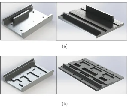
(a)
(b)
Figure 3.9: Moving Sliders and Stationary Bottom Bases of (a) Previous and (b) New Single Axis Slider Designs
and bottom view of the first design for single axis slider is given to illustrate the modifications on the components clearly.
One of the main modifications is accomplished on moving slider and station-ary bottom base to decrease the system weight. This process was required to increase the positioning performance of the system. For this purpose, thickness of these parts are reduced and partial removal of material is done in specific areas. These areas are determined considering the positions of mounting screws so that the rigidity of the component is not affected. Moreover, number of mounting screw holes on top of moving sliders are reduced without changing modularity characteristics of the slider. Another major change in moving slider and station-ary bottom base is that encoder scale holder and motor holder are manufactured as separate parts in the new design. Reason of this modification is to make the assembly and manufacturing easier. In Figure 3.9, previous and new moving slid-ers and stationary bottom bases are given to show the main modifications. As it can be seen in this figure, there are three holes at each side of new moving slider design and stationary bases. These holes are added in order to assemble linear
(a) (b)
Figure 3.10: (a) Previous and (b) New Scale Holder Designs
bearings easily. Using these holes, fine adjustments of three mounting screws at the middle of linear bearings can be done even after whole slider system is assembled together.
Another important modification is made on encoder scale holder. In previous designs, encoder scale is supported by a simple beam attached under it and sides of the encoder scale were open as shown in Figure 3.10a. Hence, assembly of the encoder scale to the desired position was not possible. For this purpose, in the most recent design, encoder scale holder is modified as shown in Figure 3.10b. In this design, the support beam is removed and a single piece scale holder is designed so that the sides are closed and encoder scale can only fit to the correct place. There is also a screw on the one side of the scale holder to tighten up the scale.
Since one of the stopper parts is attached to the encoder scale holder, screws between stopper and encoder scale holder and screws between scale holder and moving slider may exposed to sudden forces if any uncontrolled motion happens. In order to eliminate this risk, some steel pins with diameter of 4mm and 5mm are placed in these critical areas to carry those forces. For these pins, tight tolerance is used. Positions of the pins are shown in Figure 3.11.
The last major change applied on the single axis slider is about the design of encoder readhead holder. In the first design, since length of the encoder readhead holder is small as shown in Figure 3.8a, it is almost impossible to adjust 0.6mm distance between the encoder readhead and the scale without disassembling the moving slider from the stationary base. In order to overcome this problem, length of the readhead holder is increased so that the mounting screws of the holder can
Pins with 4mm diameter
Pins with 5mm diameter
Figure 3.11: Safety Pins on Encoder Scale Holder
Slider Optical Table
Figure 3.12: Single Axis Slider
be reached when the moving slider part is at one of its utmost positions. Final design of the encoder readhead holder can be seen in Figure 3.3.
After the mentioned design improvement processes, manufacturing and assem-bly of single axis slider is accomplished for the final design. A picture showing the modular single axis slider is given in Figure 3.12. This design is also used for two and three axis configurations in this thesis.
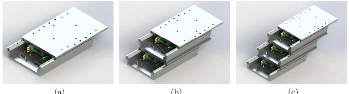
(a) (b) (c)
Figure 3.13: Example Single Axis Assembly Configurations with a One, (b) Two and (c) Three Sliders
(a) (b)
(c)
Figure 3.14: Example Two Axis Assembly Configurations Using Two Sliders in a X-Y (b) Oblique X-Y and (c) X-Z Arrangements
3.2
Assembly Configurations of Modular Slider
As mentioned in previous sections, modularity was one of the main concerns while designing the single axis slider. In this section, modularity feature of designed single axis slider system is illustrated. Several possible configurations are given for single, two and three axis systems.
(a) (b)
(c)
Figure 3.15: Example Two Axis Assembly Configurations Using Three Sliders in a X-Y (b) Oblique X-Y and (c) X-Z Arrangements
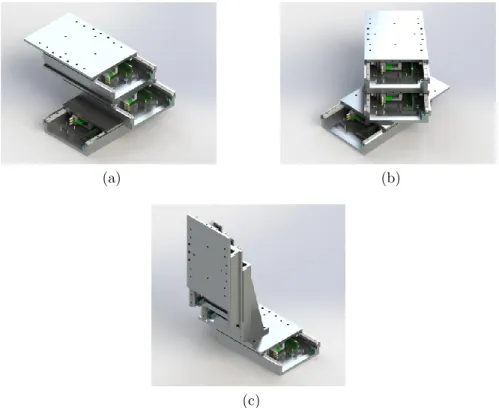
Due to the modularity property of the designed single axis slider, couple of them can be assembled to built a single, two or three axis positioning system for different applications. By assembling the single axis sliders in different forms, systems with various reachable operation areas can be obtained for many specific applications. In Figure 3.13, Figure 3.14, Figure 3.15 and Figure 3.16, several possible assembly configurations for single, two and three axis systems are given. In all of these design, maximum three number of sliders are used. However, it is possible to built different systems by assembling more than three single axis sliders to satisfy specific applications. As it can be observed from Figure
(a) (b)
Figure 3.16: Example Three Axis Assembly Configurations Using Three Sliders in a X-Y-Z (b) Oblique X-Y-Z Arrangements
3.13, range of the system increases to its triple value with the addition of two other sliders. Similarly, reachable operation areas of the two axis systems shown in Figure 3.14 and Figure 3.15 increase as the number of sliders are increased. Moreover, it is possible to adjust the limits of the reachable operation area in each axis by assembling one or couple of sliders obliquely. By adjusting the angle of the oblique sliders, a rectangular working area can be obtained instead of a square one.
As it can be observed from Figure 3.14b, Figure 3.15b and Figure 3.16, config-urations including vertical arrangements of single axis sliders, a support system is required to keep the slider in vertical position. An example support system design including a compensation system for the weight of vertical slider is explained in Section 3.3.1.
Although there are various possible assembly configurations as summarized in this section, the systems used in real time experiments are the ones shown in Figure 3.13a, Figure 3.14a and Figure 3.16a. Photographs of manufactured single axis slider and two axis slider system are given in Figure 3.12 and Figure 3.17, respectively. Details of three-axis slider system is given in Section 3.3.
Figure 3.17: Two Axis Slider System
3.3
Three-Axis Slider System
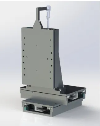
In Figure 3.18, manufactured three axis micro/nano-positioning device is shown. As mentioned previously, this specific design is composed of three of the same modular single axis sliders that are assembled perpendicular to each other. For the vertical axis, a support system is used to keep the slider in vertical position and to compensate the weight of the moving part. This system is called as counter-balance system in this thesis. In this section, details of designed three-axis micro/nano-positioning device is discussed. First, counter balance subsystem is presented. Then, details on manufacturing tolerances and assembly technique are summarized.
3.3.1
Counter Balance Subsystem
A counter balance subsystem is used in three axis positioning system for assembly of third slider. This subsystem is designed as an adapter for the single axis slider to be used in vertical position. It is composed of two main parts: an L shaped beam structure and an air piston. The purpose of the L shaped beam is to
Figure 3.18: Three Axis Micro/Nano-Positioning System
support the slider in vertical position. On the other hand, air piston is used to compensate the weight of the sliding part so that similar control inputs can be used in both directions in vertical for high precision positioning. In addition to these main parts, a connector, a spherical joint and a pressure regulator are also used in counter balance system. The connector is used to connect the moving slider of vertical stage to the air piston via a spherical joint. On the other hand, pressure regulator is used to adjust the air pressure going to the air piston.
In Figure 3.19, counter balance subsystem used in three-axis positioning sys-tem is shown. In this subsyssys-tem, air pressure coming from the common source to the piston is adjusted using an analog pressure regulator. Hence, when a part is assembled on the vertical slider for a specific application, difference in the weight of the vertical sliding part can be compensated by using the regulator to adjust the pressure coming to the piston. In the three axis positioning system, when
Spherical Joint Pressure Regulator Slider L Beam Air Piston Connector
Figure 3.19: Counter Balance Subsystem
there is no additional part is assembled, 6 bar of pressure coming from the com-mon source is reduced to approximately 1 bar using the pressure regulator and fed into the air piston to compensate the weight of the moving slider in vertical axis.
3.3.2
Manufacturing and Assembly Tolerances
Tolerances are crucial while designing, manufacturing and assembling a system to work in nanometer level precision. In order to obtain maximum performance from actuator and sensor units, manufacturing and assembly tolerance values should be determined carefully for the assembly regions of these parts.
A 3D drawing of the slider is given in Figure 3.20 showing the tolerance critical sections. As it can be observed in this figure, the important sections in terms of tolerances are the ones that encoder and linear motor are attached to the system. Moreover, top and bottom surfaces of the slider are also important in terms of
(a) Motor Core Magnet Track Encoder Scale Encoder Readhead (b) Motor Core Magnet Track Encoder Scale Encoder Readhead (c)
Figure 3.20: (a) Tolerance Critical Sections of Single Axis Slider with Detail Views of (b) Section A and (c) Section B
their flatness and surface roughness values since these surfaces are the contact regions while mounting the slider on the optical table or another slider.
Figure 3.20c shows the assembly region of the encoder readhead and the scale. In order to obtain measurements with minimum error from the encoder, they should be assembled according to some predefined specifications. For this pur-pose, tolerances for the regions where the encoder readhead and the scale attached are determined according to the instructions supplied by the encoder manufac-turer [15]. Therefore, surface flatness tolerance is chosen to be 0.01mm for these regions. Moreover, distance between the encoder readhead and the scale is to be 0.6mm, hence tolerance for this distance is determined as 0.02mm to be satisfied during the assembling process. Tolerances for positions of screw holes that the encoder head and the scale are to be attached are chosen as 0.05mm in each direction.
Similar to encoder assembly, flatness of the surfaces that the linear motor is attached is critical. Flatness tolerance of the assembly surfaces shown in Figure 3.20b is chosen to be 0.01mm. Position of the motor is also be arranged by using 0.05mm tolerance in the locations of the mounting screw holes.
Flatness properties of the top and bottom surfaces of single axis sliders are also important for them to be assembled on the optical table or to be assembled together to built three axis positioning system with nanometer level positioning precision. Therefore, as in encoder and linear motor assembly, geometric tolerance for flatness of these surfaces is chosen to be 0.01mm.
Chapter 4
Encoder Resolution Improvement
Method
In this thesis, presented single axis slider system includes a linear incremental optical encoder as a feedback sensor to obtain position information. However, measurement resolution of the encoder used in the system is 1µm since the scale grating is 4µm in pitch. Precision positioning in sub-micrometer level is impos-sible using this encoder. Hence, in order to achieve nanometer level positioning performance with overall system, it is crucial to increase the resolution of the encoder used. Signal processing techniques for the interpolation of the available encoder signals serves further improvement of the encoder resolution by deriving intermediate position values out of the original encoder signals.
In this chapter, a new adaptive approach to obtain high-resolution position information out of the original encoder signals is presented. First, the overview of the approach is given to give the basic idea behind it. Next, the adaptive encoder signal correction technique used before the interpolation process is presented with the mathematical foundation. Then, signal interpolation method is discussed in detail. Generation of binary pulses from the interpolated signals and deriving position information using these binary pulses are explained. Lastly, practical constraints that limit the application of this approach is summarized.
4.1
Overview of the Proposed Approach
As briefly discussed in [29], our motivation in this approach is to generate high-order quadrature sinusoids from the original encoder signals so that any deviations or distortions in these signals can be tolerated. For this purpose, an adaptive sig-nal conditioning step to obtain ideal sunusoids with quadrature phase difference is applied before the interpolation process. Then, mapping of the first-order signals to higher-order ones is accomplished by a quick access look-up table. With the conversion of the higher-order sinusoids to binary pulses, high-resolution position information is obtained.
Proposed method features two main steps: (1) correction of signal errors and (2) interpolation of corrected signals. For the correction step, an adaptive correction method is adopted to compensate the encoder signal errors including amplitude difference, mean offsets, and quadrature phase shift errors. Adaptation is performed by the recursive least squares (RLS) with exponential forgetting and resetting. The need for adopting an adaptive correction technique is due to the dynamic characteristics of the errors as well as the applicability on different encoders without any modification.
For high precision positioning applications, assembly and alignment of the encoder is very important to attain required accuracy and precision. However, for closed systems or long range positioning systems, it may not be possible to align the encoder to obtain perfect quadrature signals. Characteristics of the resulting signal may change through the motion. Hence, adaptive approach used in this section is more suitable for the systems where the signal errors change dynamically. Moreover, adaptive characteristics of the correction step makes the method applicable to different encoders without requiring any modification in the algorithm. Due to the adaptive approach in the correction method, different error characteristics of different encoders can be compensated without changing any parameter in the algorithm.
In the second step of the proposed method, interpolation of the corrected sig-nals is satisfied by a look-up table based approach. In this approach, the basic
Encoders Signal Correction Index Calculator Parameter Adjustment Look-up Table Pulse Generator Counter u1 u2 û1 û2 i u1n u2n A B Position λ θ
STEP 1: ADAPTIVE ENCODER SIGNAL CORRECTION
STEP 2: LOOK-UP TABLE BASED INTERPOLATION
idea is to obtain high-order sinusoids from original encoder signals by mapping the original signals to high-order ones online with the help of a quick access look-up table. Since the look-up table is formed offline, computational effort is consid-erably less compared to the previously mentioned online interpolation methods. At the end of the interpolation stage, position information can be derived from conversion of the high-order sinusoids to binary pulses. This conversion is also im-plemented on the software hence it is accomplished without using any additional hardware such as high precision ADCs.
An overall flow diagram for the proposed approach is shown in Figure 4.1. In this figure, signal correction and interpolation steps are labeled as Step 1 and Step 2, respectively. The correction step takes the encoder signals u1 and u2
and generates signals ˆu1 and ˆu2 as corrected quadrature signals. In order to
compensate the errors in u1 and u2, a set of correction parameters θ is calculated
using RLS with exponential forgetting and resetting in the parameter adjustment stage. Here, our parameter adjustment rule uses the current encoder signals u1 and u2 and corrected signals ˆu1 and ˆu2 from previous iteration. λ is the
forgetting factor or discounting factor. When the correction step is completed, index calculator generates index, i, for signals to obtain corresponding high-order sinusoid values, u1n and u2n, from the look-up table. The look-up table is
constructed using the correct values of high-order sinusoids since the corrected signals coming from the Step 1 are calculated with sufficient precision through the adaptive correction scheme. Therefore, the look-up table can be generated offline without requiring high computational effort. Using high-order sinusoids, pulse generator generates quadrature binary pulses A and B. As mentioned previously, this process is performed in the software part without requiring high-precision ADCs. Finally, position value is calculated by detecting zero crossings of high-resolution binary pulses.
4.2
Adaptive Encoder Signal Correction
(Step 1)
Before the interpolation stage, it is crucial to correct the errors in the original encoder signals to prevent high interpolation errors. Common errors affecting the quadrature encoder signals are the amplitude difference, the mean offsets and the quadrature phase shift errors. In Figure 2.5, an exaggerated illustration of these errors are given. In this figure, mean offsets are denoted as m1 and m2,
amplitudes are A1 and A2 and φ is the phase shift error.
In this section, an adaptive approach is used to correct the errors. In some applications, it is possible to have similar error characteristics throughout the motion. In these cases, the error can be compensated using offline correction methods given in [16] and [31]. On the other hand, in some cases where the encoder alignment cannot be performed effectively or where the systems have long range of movement track, the errors change throughout the motion. For such cases, adaptive approaches may be adopted to track the errors better in order to obtain high-resolution. Moreover, with an adaptive approach, applicability of the method on different encoders with different error characteristics can be satisfied without requiring any modification in the algorithm. For this purpose, RLS with exponential forgetting and resetting method is developed to adjust correction parameters online.
In order to develop the mathematical foundation (i.e. (4.1)-(4.15)) for our proposed method, we will start with the formulation given in [31].
An ideal set of quadrature encoder signals with amplitude of A, u1i and u2i,
can be expressed as
u1i= A cos α
u2i= A sin α
(4.1)
Relation between real (u1 and u2) and ideal encoder signals (u1i and u2i) can be written as u1 = u1i+ m1 u2 = 1 R(A1cos(α − φ)) + m2 (4.2)
where m1 and m2 are mean offset values and φ is the quadrature phase shift
error. In (4.2), R is the gain ratio (A1/A2) where A1 and A2 are amplitudes
of actual encoder signals. Using (4.1) and (4.2), a conventional least squares formulation can be obtained as shown in (4.3) and (4.4).
θ1u12+ θ2u22+ θ3u1u2+ θ4u1+ θ5u2 = 1 (4.3) where θ1 = (A21cos 2φ − m2 1− R 2m2 2− 2Rm1m2sin φ)−1 θ2 = θ12R 2 θ3 = 2θ1R sin φ θ4 = −2θ1(m1+ Rm2sin φ) θ5 = −2θ1R(Rm2+ m1sin φ) (4.4)
It is possible to calculate θi (i = 1, 2, , 5) constants offline using least squares.
In order to use a Recursive Least Squares (RLS) approach with exponential for-getting, (4.3) can be re-written as shown in (4.5).
ϕ1(t)θ1(t) + ϕ2(t)θ2(t) + ϕ3(t)θ3(t) + ϕ4(t)θ4(t)
+ ϕ5(t)θ5(t) = 1
or
ϕT(t)θ(t) = 1
(4.5)
parameters to be determined and ϕ0is are known functions depending on actual encoder signal values. Then, the parameter update and regressor vectors given in (4.6) are obtained.
ϕT(t) = [u21(t), u22(t), u1(t)u2(t), u1(t), u2(t)]
θ(t) = [θ1(t), θ2(t), θ3(t), θ4(t), θ5(t)]T
(4.6)
The objective of a RLS with exponential forgetting and resetting algorithm is to determine the parameters so that (4.5) is satisfied with minimum possible error. For this purpose, a loss function given in (4.7) is determined so that the chosen θ should minimize its value.
V (θ, t) = 1 2 t X k=1 λt−k(1 − ϕT(k)θ)2 (4.7)
where k is index and λ is forgetting factor such that 0 < λ ≤ 1. By adjusting the value of λ, contribution of old data to loss function is controlled so that most recent data is given unit weight whereas old data is weighted by λs, where s is
number of time intervals elapsed from the old data.
Then, the recursive parameter adjustment law can be obtained as follows:
θ(t) = θ(t − 1) + K(t)(1 − ϕT(t)θ(t − 1)) K(t) = P (t − 1)ϕ(t)(λ + ϕT(t)P (t − 1)ϕ(t))−1
P (t) = (I − K(t)ϕT(t))P (t − 1)/λ
(4.8)
where I is identity matrix and P is a non-singular matrix which can be chosen as P = κI, κ is a large number.
For simplicity, time index t will be dropped from the equations from this point forward, although each correction parameter is time-varying. For calculating θ0is using (4.8), the correction parameters (i.e.A1, R, m1, m2 and φ) can be obtained
0 200 400 600 800 1000 1200 0.4 0.5 0.6 Time [ms] A1 [V] 0 200 400 600 800 1000 1200 1 1.05 Time [ms] R 0 200 400 600 800 1000 1200 0 0.02 Time [ms] m1 [V] 0 200 400 600 800 1000 1200 0.02 0.04 Time [ms] m2 [V] 0 200 400 600 800 1000 1200 −0.02 0 0.02 Time [ms]
Phase Shift Error
[rad]
Figure 4.2: Encoder Signal Parameters Recorded Through 120mm Motion of the Single Axis Slider
φ = arcsin(θ3/ q 4θ1θ2) R =qθ2/θ1 m1 = (2θ2θ4 − θ5θ3)/(θ23− 4θ1θ2) m2 = (2θ1θ5 − θ4θ3)/(θ23− 4θ1θ2) A1 = v u u t 4θ2(1 + θ1m21+ θ2m22+ θ3m1m2) 4θ1θ2− θ32 (4.9)
As a result, the corrected quadrature signals, ˆu1 and ˆu2 can be calculated
using the correction parameters obtained in (4.9) as follows:
ˆ u1 = 1 A1 (u1− m1) ˆ u2 = 1 A1cos φ
((u1− m1) sin φ + R(u2− m2))
(4.10)
Using this method, correction parameters are adjusted with each iteration re-cursively considering the effects of parameter values from the previous iterations.
0 0.2 0.4 0.6 0.8 1 1.2 1.4 x 10⁻⁴ −2 −1 0 1 2 Time [s] Amplitude [V] û 2 û1 (a) 0 0.2 0.4 0.6 0.8 1 1.2 1.4 x 10⁻⁴ −2 −1 0 1 2 Time [s] Amplitude [V] û 2 û1 (b)
Figure 4.3: Corrected Encoder Signals Using RLS (a) with and (b) without Re-setting
Hence, slow changes in the parameters can be covered efficiently. In Figure 4.2, changes in the signal amplitude, gain ratio, mean offsets, and phase shift errors recorded through 120mm motion of our single axis slider are shown. For short range movements (less than couple of hundreds of micrometers), parameters can be assumed to change smoothly and continuously. However, as it is also observed in Figure 4.2, these parameters may change more dramatically for long range motions. For such cases, a standard RLS with exponential forgetting cannot es-timate the parameters effectively. Hence, in long range motions, resetting is used to cover the significant parameter changes. For this purpose, the matrix P in the RLS algorithm given in (4.8) is reset periodically to its initial value of κI. As a result of resetting, parameter estimate is updated with a larger step size so that significant changes in the parameters can be estimated well since the gain K(t) in (4.8) gets larger [40]. In Figure 4.3, corrected encoder signal data obtained through the end of 120mm motion of the slider is given for RLS with resetting and without resetting cases. It is obvious that a better correction of the encoder signals is accomplished using RLS with resetting where long range motion is the
0 0.5 1 1.5 2 2.5 3 3.5 x 10⁻³ −1 −0.5 0 0.5 1 Time [s] Amplitude [V] û 1 and û2 u1 and u2
Figure 4.4: Corrected and Original Encoder Signals
focus of interest. As shown in Figure 4.3b, when there is no resetting of matrix P in the RLS algorithm, corrected signals still contain amplitude, mean offset and phase shift errors at the end of long range motions. The amplitude error for no resetting case is measured around 14% − 16%. Mean offset errors can reach up to 0.1V and phase shift error is about 2.5 − 3 degrees. Although the phase shift error seems small, when high-resolution measurements are concerned, it is not acceptable. Moreover, these errors will be amplified when an interpolation method is applied to obtain high-resolution. Illustration of the encoder signals obtained before and after correction using RLS with exponential forgetting and resetting is given in Figure 4.4. In order to illustrate the quadrature phase shift of the corrected signals more clearly, variation of amplitude of corrected signals between 0 and π/2 radians are given in Figure 4.5. As it can be observed in this figure, corrected signals have a phase difference of π/2 as desired.
4.3
Look-up Table Based Signal Interpolation
(Step 2)
In order to derive intermediate position values, corrected encoder signals are interpolated. For this purpose, high-order sinuoids are generated by mapping the corrected sinusoidal encoder signals to high-order ones. Here, calculation of higher order sinusoids using general formulations in (4.11) can be a tedious
0 pi/32 pi/16 3pi/32 pi/8 5pi/32 3pi/16 7pi/32 pi/4 0 0.2 0.4 0.6 0.8 1 Angle [rad] Amplitude [V]
Figure 4.5: Verification of Quadrature Phase Difference Between Corrected Sig-nals operation. sin(nα) = n X k=0
cosk(α) sinn−k(α) sin(1
2(n − k)π) cos(nα) =
n X k=0
cosk(α) sinn−k(α) cos(1
2(n − k)π)
(4.11)
where the first parenthesized term is a binomial coefficient and n is the order. Calculating values of high-order sinusoids using original first order sinusoids may reduce accuracy. Moreover, real time performance of the interpolation process can be low due to high computational burden. In our method presented here, we use a look-up table based interpolation method for mapping of original encoder signals to high-order sinusoids at high process speeds. For this purpose, a quick access look-up table is populated offline. The look-up table used in this section directly uses the actual numerical values of high-order sinusoids since the corrected signals coming from the adaptive signal correction step are sufficiently close to the real sinusoidal signal values. Moreover, as previously mentioned, signal characteristics change significantly in long ranges and different encoders may have different signal characteristics. Hence, it is much more practical to use the mathematical values of high-order sinusoids. Also, the look-up table generation task in this method is practical and the same look-up table is applicable to different encoders or operation conditions.