A NOVEL APPROACH TO 3-DIMENSIONAL HOLOGRAPHIC TELEVISION
DISPLAY : PRINCIPLES AND SIMULATIONS
Gozde Bozdagz, Levent Onural, and Abdullah Atalar
Electrical and Electronics Eng. Dept., Bilkent University
Bilkent, Ankara, 06.53:3 Turkey
ABSTRACT
In this paper, we present a new technique for the display end of a holographic 3-dimensional television system and carry out the computer simulations. The used technique is based on the reproduction of the de-sired pattern, in our case the hologram, using traveling surface waves. The proposed method is simpler and more efficient than the methods available in the litera-ture and it solves the display resolution and refreshing rate problems completely. As a result of simulations, we see that the proposed system will work as desired when implemented in real time.
1. INTRODUCTION
Presenting the information around us in three-dimension is more interesting than presenting it in a two-dimensional projection to a viewer. There are two well-known techniques for displaying three-dimensional views: steoroscopy and holography. Stereoscopy works on the principle that much of our perception of depth in a scene is due to the fact that our two eyes produce dissimilar images. By synthe-sizing these two views the brain can get the depth information. Therefore, any recording system which records a scene from two different proper angles, and a means to transfer each image to the corresponding eye,
will
generate a three-dimensional perception. An important limitation of this technique is the lack of proper parallax in the vertical direction. So, it does not give a true three-dimensional display. On the other hand, holographic images show the full paral-la..x effects observed in real life. In holography, the information-carrying optical waves which come from the three-dimensional environment are somehow du-plicated in the absence of the original source. As the light waves spread out, the viewers at different loca-tions perceive the waves exactly as they came fromthe original object and see it in three dimensions. Some three-dimensional holographic television sys-tems, including both the camera and the display ends, are reported in literature ([5), [6]) but the display problems of 3-D moving imagery prevents them to be introduced into widespread use. In this paper we pro-pose a new display device which solves the display resolution problem significantly. In addition, the re-freshin" rate of this device is more than enough for 3-D
m~ving
imagery. The technique proposed in this paper is conceptually different than the available tech-niques which use the direct scanning of the hologram.2. FORMING A PATTERN BY SUPERPOSING PROPAGATING WAVES
The SAW (surface acoustic wave) device that will be used as the medium of display is assumed to have an array of electrodes attached to it. If signals are ap-plied to all of the electrodes, propagating \Vaves from the electrodes will superpose to form a time-varying surface field pattern on the crystal [8]. There is a mathematical relationship between the time-varying array of electrode signals and the corresponding time-varying field on the crystal surface. Through the in-version relationship, the forms (time-variations) of the electrical signals can be found to get a prescribed sur-face field pattern at a specific instant of time. This re-lationship is given by the following equation in terms of Fourier transforms as:
111-117
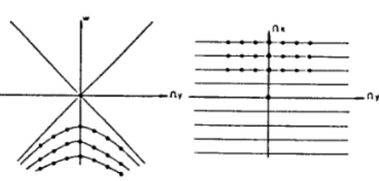
Figure 1: Sample locations after and before transfor-mation
i.e., we have to know F(d, e) ford= 0, ... , N'-1 and e
=
0, ... , P.I'-1.After interpolation and resampling, taking the in-verse DFT of F(d, e) ford= O ... N'-1, e = O ... M' -1 will give us the discrete time signals /(a,
b)
whereN'-1 M'-1
f(a,b)
=
L L
F(d,e)e-i1fra.de-i1.frbe (10)n=O m=O
for a = O ... N'-1, b = O ... }vf'-1.
As we are working in discrete domain we need the samples of llt(w.,,wy)· Sampling in frequency domain yields periodic repetition of 1/;(n, m) in space domain as given by Eq.11.
llt(k, I)= lli(w.,,wy)lw ..
=*k
H~
·lj;(n+Ni, m+Mj)(ll)w~=if1 I,J
where N and M are the periods.
After coordinate transformation given by Eq.7 we get
F(d, e)= F(w, u)l ..
=1fr«
~ ~
f(a+N'i, b+M'j).(12) •=1;'fre I,}As we have a periodic input pattern given by the right hand side of Eq .11, the time signal that generates it must also be periodic as given by the righthand side of Eq.l2, but we have overlaps in the time signal. The reason for these overlaps is the infinite extent of the time signal in both variables t and y. If one wishes to have a perfect reconstruction of the periodic pattern,
Li
Li
1/J(n
+
Ni, m+
Mj), then an infinite array ofelectrodes all radiating at all times must be consid-ered. However, we must restrict ourselYes to a finite number of electrodes, i.e. a finite number of periods of the time signal in y-direction. If only one period (in y-direction) of the time signal is chosen, then all of the 2-D periods of the space pattern degrades but the de-gredation is less in the main period. The dede-gredation is due to information missing because of not using all the periods. Even though we can get a perfect recon-struction by using an infinite array of electrodes we can not get rid of the ovelapping effect due to the in-finite extent of the time signal
[1], (4], [2].
This effect can be decreased by proper choice ofX
and }vf, i.e. by zero padding the input pattern.3.3. Wave Propagation
If we have a point source located at (x0 , Yo) and
oscillating with respect to time as eiwt, the field on the surface becomes
(13)
If we use the Fourier Transform relationships and the superposition property, we can find the total field, when we have (k
+
1) sources with excitations x;(t) located along y and at x = 0, ask E x.(t - yx2+(y-y,)2)
E(t, r)
=
L
o • c ' .i=O 271'(x2
+
(y-y;)2)~(14)
4. SIMULATION RESULTS
Fig.2.a shows the simulated hologram of a 2-D flower pattern. The electrode signals are obtained as indicated by the theory using computation. If these signals are applied to the electrodes, the propagating waves from each electrode will superpose to generate the pattern shown in Fig.2.b at a specific instant. Us-ing this new pattern as the hologram (which would be on the surface of the SAW), the original object (which is a 2-D, i.e., flat pattern located in 3-D space, for this figure) can be reconstructed as in usual holog-raphy. This will be done optically in the real system, but here the reconstruction result is obtained through simulation. This is shown in Fig.2.c. For comparison, the same simulation method is applied to the original hologram of Fig.2.a. The result of this simulation is shown in Fig.2.d. Here, the measure of success is the similarity of Figures 2.c and 2.d. The stripes are due to the well known holographic effects, and not due
3. DIGITAL SIMULATION
In this part, we simulated the holography record-ing and reconstruction processes, the inversion rela-tionship to find the time signals from the holographic pattern, and propagation of the waves to get the holo-graphic pattern back, in three steps.
3.1. Discrete Model For Off-axis Hologra-phy
Mathematical models for continuous off-axis holog-raphy can be found in the literature (for example
[3),[4]).
By using the Fresnel approximation and by assuming that the object is made up of of vanishingly thin slices in the z-direction, we can write the inten-sity of the field distribution at a distance z from the object plane, i.e. the hologram, aslz(x, y)
=
R~+
la(z, y)*
*h.(x, y)l2+
R0e-jbsin(ll)[a(x, y)
*
*hz(x, y)]+
Roeikrsin(ll)[a*(x, y)*
*h;(x, y)].(2)
where h.(x, y)=
ilz
eh7(x'+y').Since the field is represented as a two-dimensional convolution, it can be modeled as the output of a two-dimensional linear system, where the system impulse function is hz ( x,
y).
For simulation, a discrete impulse function hz0(n, m) must be determinedcorrespond-ing to the continuous impulse function h.(x, y). In
[3]
a detailed analysis of sampling of h.(x, y) to get h.0(n, m) is given, so only the results will bemen-tioned here. The discrete impulse response hz0(n, m)
is given by { h.(Xn, Ym) if
lnl
~ Nh 2 -1 , hzo(n,m)
=
lml
~ M,.2-l 0 elsewhere (3)where Nh and Mh give the discrete size of the filter in dimensions n and m respectively.
The input function can also be discretized similarly to yield aD(n, m)
=
a(Xn, Ym).In our implementations, we chose X
=
Y, i.e., N=
Al. For the purpose of normalization, a new variable a, which is related to the sampling of the optical hologram, andf3
for the reference beam are introduced [3), [4], such that(4)
{f;
f3 =
27racos(O)yN'
(5)Now the discrete hologram can be written as
Similar operations can be done for the reconstruc-tion step. In order to increase computareconstruc-tional effi-ciency, circular convolution can be carefully used in-stead of linear convolution.
3.2. Digital Simulation Of Inversion Rela-tionship
The simulations performed in this part tests whether the inversion relationship is correct and how the actual system works. The inversion relationship between the source signal f(t, y) and the surface field
'l/J1(x,y) is given in the first section in continuous do-main. In practice the length of the crystal edge where the sources are located is finite; the source is not con-tinuous but a discrete array. In simulations, we car-ried out all the tasks in discrete time. In a way, this is an advantage; because we have chance to consider the discrete/finite source effects which we will face with in the actual system. The only thing which we must take care of during the simulations is the aliasing and periodicity effects as shown in this section.
Let us denote the discrete surface wave pattern as
r/Jt,
0(n,m) for n=
Q ... N- 1,m=
O ... J f - 1, and the discrete excitation signal by J( a, b) for a=
O ... N' - 1, b
=
O ... J1'- 1. One can take the DFT (Discrete Fourier Transform) of ¢1,0 (n, m) to get'l11,0 (k, l) If there is no aliasing, the elements of this
two-dimensional array are the samples of the contin-uous Fourier transform 'l11,(f2x, f2y)· Knowing these
samples, which are located on a rectangular grid, we can also find the samples of the F(w, u) through the relation 7
=
'l11,(Uk, Vl)=
-IUkl cUk F(k•z·).
Uk JU2k2
+
V2f2 ' (7)where 0 $ k•
<
N', 0 $z·
<
M'. U and V are the sampling periods, c is the propagation speed of the wave, N' and M' are given by Eq.8 and Eq.9:(8)
M'
=
[V(M-1)].
(9)However, the sample locations in this case do not form a rectangular grid. The locations are shown in Fig.l. In order to use an inverse DFT to get the dis-crete time signals, uniformly sampled data is required;
Q
t:.J
(a)D
(c)
(b)D
(d)Figure 2: (a)The simulated hologram of a 2-D flower pattern, (b) The reconstructed hologram after radia-tion of time signal, (c) Reconstrucradia-tion from hologram in (b), and (d) Reconstruction from hologram in (a).
to the inadequacy of neither the proposed method, nor the computational errors. The stripes are due to a small angle between the reference and the object beams during the simulated recording. The similarity of Figures 2.c and 2.d are evident, and this indicates that the proposed system will work.
In the simulations 64x128 images are used. The time signals are for 256 electrodes and each one has 512 points. All simulations are carried out in our image processing laboratory using SPARC worksta-tions at the Bilkent University. Our preliminary stud-ies show that the proposed system can be easily con-structed with the available technology and with the application of digital signal processing techniques.
5. CONCLUSION
As a result of simulations, we see that the pro-posed inversion relationship enables us to have a 3-dimensional television where the display resolution and sequential write-and erase rate are no more prob-lems.
In simulations, we can handle the effects due to discrete/finite source which we will face with in the actual system. However, the system will be expected to differ from the simulation results in some aspects, when implemented. For example, in simulations, the reflections from the edges of the crystal are neglected,
and also the number of electrodes which are treated as point sources, is varied without considering physi-cal limitations. On the other hand, in actual system implementation the errors due to round off,etc. will no more effect the resultant pattern as in simulations. Also, in actual system there will be no stripes in the reconstructed images which is because of the small an-gle between the reference and the object beams during recording. Increasing the angle makes them disap-pear, but in the case of simulations this brings more computational complexity due to increased resolution requirements.
So, if the necessary number of electrodes can be used and the information content of the input image is mainly distributed in the middle, we can say that the actual system will work as shown by the simula-tion results. Furthermore, the simulator may be easily improved to consider some non-ideal real life situa-tions. This may result in generation of more appro-priate electrode signals which may cancel undesirable effects of non-ideal situations.
6. REFERENCES
1. L. Onural, and A. Atalar, "An Acousto-Optical Holographic Three-Dimensional Television Dis-play," US Patent Application number 07/684,845. 2. G.Bozdagt, L. Onural, A. Atalar, "Simulation of
a New Holographic 3-Dimensional Television Dis-play," ISCIS VI, Proc. Si.xth Int. Sym. on Comp. And Info. Sciences, Oct. 1991, pp. 963-973. 3. L. Onural and P.D. Scott, "Digital Decoding of
In-Line Holograms," Optical Engineering, vol.26, no.ll, pp.l124-1132, Nov.l987.
4. G. Bozdagt, "Simulation of a 3-D Television Dis-play," M.S. Thesis, Bilkent University, Dec. 1990.
5. J.S. Kollin,et.al. "Real-Time Display of 3-D Computed Holograms by Scanning the Image of an Acousto-Optic lvfodulato'f', Proc. of the 2nd Inter. Congress of Optical Sciences and Engineer-ing, 1989.
6. S.A. Benton, et.al. "Experiments in holographic Video Imaging," Proceedings of the SPIE Insti-tute on Holography, 1991.