Computer Aided Pulsator Control in Milking Systems
Mehmet Ali DAYIOĞLIP Hasan SILLELP Mustafa VATANDAŞ' Recai GÜRHAN'
Geliş Tarihi : 07.12.1998
Abstract: In this study, a computer based system was developed for controiling the electronic pulsators used in milking . By changing parameters of the pulsation rate and pulsator ratio, pulsation characteristics were measured at different vacuunn pressures using a written software. The pulsation rate between 40 - 70 min-1, pulsator ratio between 50 - 75 % and vacuum pressure between 40-60 kPa were altered in experiments. The limping was remained in the level of 0.1 % in nominal cperating conditions (50 kPa, 60 min -1 and 70 %). The greatest limping value was mcasured as 2.9 % in de termined trial intervals. As a result, the pulsation characteristics of the control system were obtained as mentioned in intetnational standard.
Key Words: Puisator, computer aided control, puisation ratio, pulsation rate, limping
Süt Sa
ğı
m Sistemlerinde Bilgisayar Tabanl
ı
Pulsatör Kontrolu
Özet: Bu çalışmada, süt sağımında kullanılan elektronik pulsatorierin kontrolu için bilgisayar tabanlı bir sistem geliştirilmiştir. Geliştirilen yazılırnla nabız frekansı ve nabız oranı parametreleri değiştirilerek, fandı vakum basınç değerlerindeki pulsatör karakteristikleri olçülmüştür. Denemelerde nabız frekansı 40-70 min , nabız oranları % 50-75 ve vakum basıncı 40-60 kPa aralıklannda değiştirilmiştir. Nominal işletme koşullarında (50 kPa, 60 min -I ve 0/070) aksama °k 0.1 düzeyinde kalmıştır. Belirlenen deneme aralıklannda aksamanın en büyük değeri % 2 9 olarak ölçülmüştür. Sonuç olarak geliştirilen kontrol sisteminin uluslararası standartlarda bildirilen pulsasyon karakteristiklerini sağladığı belirlenmiştir.
Anahtar Kelimeler: Pulsatör, bilgisayar tabanlı kontrol, nabız oranı, nabız frekansı, aksama
I ntrod ucti on
The basic requirements for the construction and performance of milking machines for animals are determined by physiology of the animal and the need for a high standart of hygiene and milk quality. In addition, the equipment must be effective and easy to use and test (ISO 5707, 1996).
Pulsator is one of the most important element of milking vacuum systems. There are four types: mechanic, hydrolic, pneumatic and electronic. Some electronic milking systems include a centrally pulsator control unit (Cant ve Reitsma, 1979).
The pulsation cyclic opening and closing of a
teatcup liner. Pulsation rate is the number of pulsation cycles defined as one complete liner movement sequence
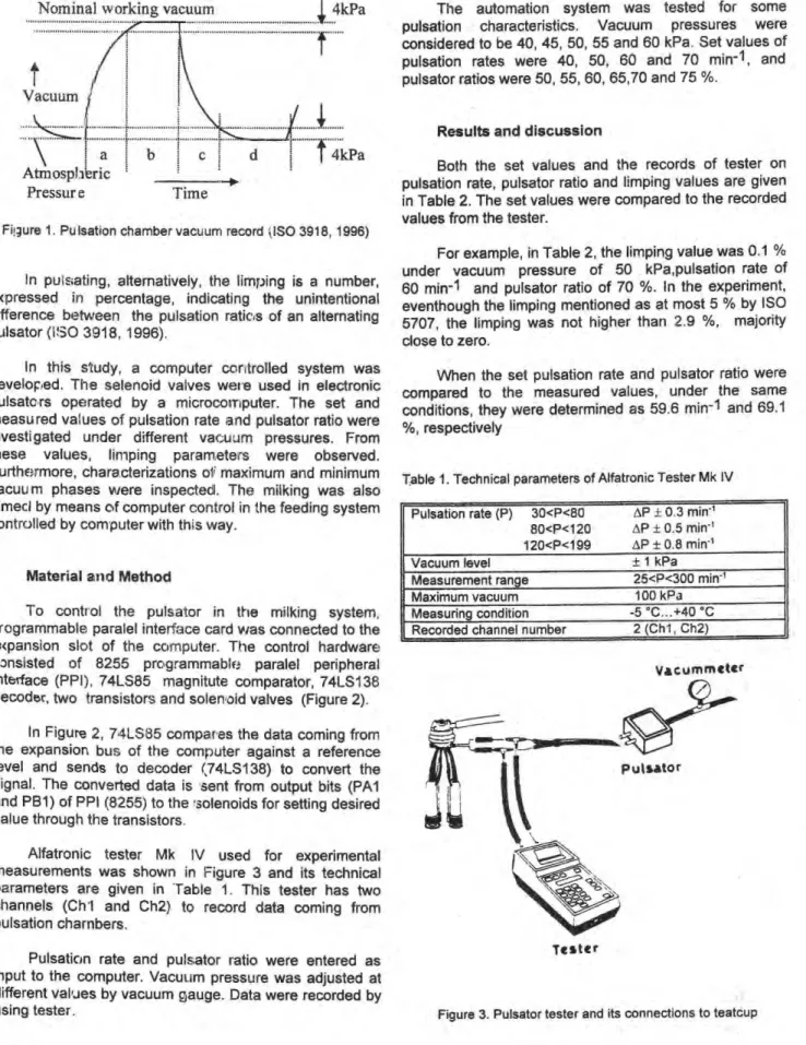
per minute. Pulsator ratio is one of the most important parameters in pulsation system. The pulsator ratio is duration of the increasing vacuum phase and maximum vacuum phase as a percentage of the complete pulsation cycle in the pulsation chamber vacuum record. Each cycle of the record of pulsation chamber vacuum consists of four phases (ISO 3918, 1996):
• Increasing vacuum phase (a),
• Maximum vacuum phase (b),
• Decreasing vacuum phase (c),
• Minimum vacuum phase (d).
1 Ankara elniv. Ziraat Fak. Tarım Makinalan Bölümü - Ankara
The duration of each phase as a percentage of the total cycle time is measured between the points at which the record intersects abscissae drawn at 4 kPa below nominal working vacuum and above atmospheric pressure (Figure 1).
The pulsator ratio (PR) is expressed by the following formula (ISO 3918, 1996) :
a +b
PR = x100
a+b+c+d
where, "a+b" : expansion time (milking phase), "c+d" : compression time (massage phase), "a+b+c+d" : total cycle time.
The pulsator ratio should be within + 5 units of percentage of the value stated by the manufacturer. Phase "d" of the pulsation chamber vacuum record should be not values either less than 15 % or less than 150 ms. Phase "b" of the pulsation chamber vacuum record should be not less than 30 % (ISO 5707, 1996).
On the other hand, "a+b", "b" and "d" phases and pulsation rate have to be changed according to race, age, health and lactation time of the cow.
t 4kPa
Nominal working vacuum 4kPa
t
VacuumAtmospl
ı
eric
Pressur e
d Time2 TARIM BILIMLERI DERGISI 1999, Cilt 5, Sayı 2
Fiı;ure 1. Pulsatıon chamber vacuum record ı,IS0 3918, 1996)
In pul ıating, alternatively, the limping is a number,
expressed in percentage, indicating the unintentional ciifference between the pulsation ratic,s of an alternating pulsator (II30 3918, 1996).
In this study, a computer coratroiled system was developed. The selenoid valves were used in electronic pulsatc rs operated by a microcomputer. The set and measured values of pulsation rate and pulsator ratio were investigated under different vaeuum pressures. From
these values, linıping parameters were observed.
Furthermore, characterizations of maximum and minimum vacuu m phases vıere inspectedl. The milking was also aimeci by means cif computer control in the feeding system controlled by computer with this ■.vay.
Material and Method
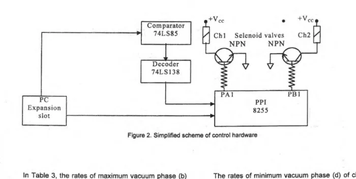
To control the pulsator in the milking system, programmable paralel interface card vıas connected to the expansion slot of the cc,rnputer. The control hardware consisted of 8255 programmable paralel peripheral interface (PPI), 74LS85 magnitute comparator, 74LS138 decoder, two transistors and solenoid valves (Figure 2).
In Figure 2, 74LS85 compares the data coming from the expansion bue of the computer against a reference level and sends to decoder (74LS138) to convert the signal. The converted data is sent from output bits (PA1 and PB1) of PPI (8255) to the solenoids for setting desired value through the transistors.
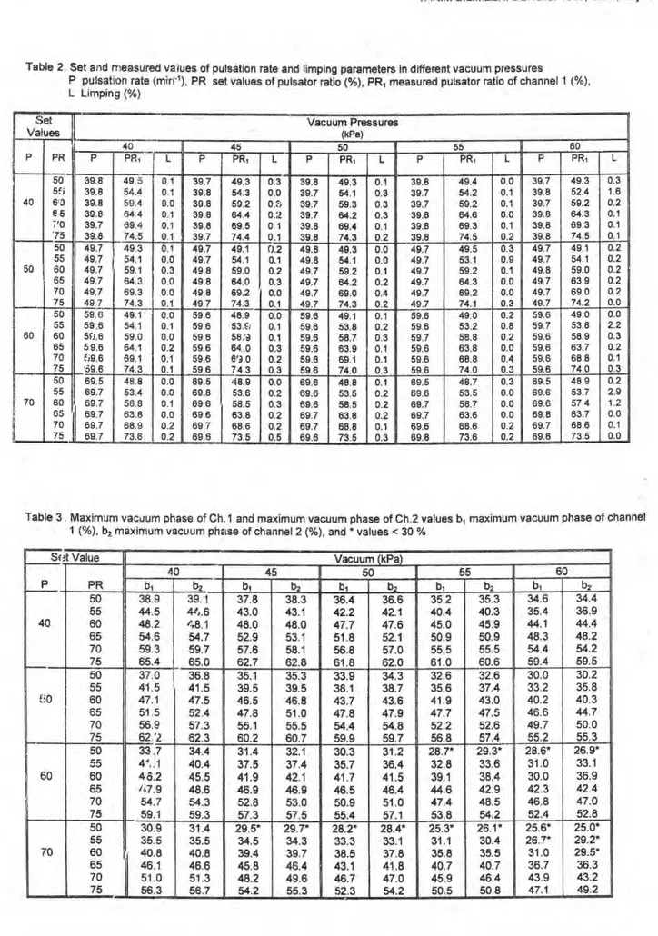
Alfatronic tester Mk IV used for experimental measurements was shown in Figure 3 and its technical parameters are giyen in Table 1. This tester has two channels (Ch'I and Ch2) to record data coming from pulsation charnbers.
Pulsation rate and pulsator ratio were entered as input to the computer. Vacuum pressure was adjusted at different values by vacuum gauge. Data were recorded by using tester.
The automation system was tested for some pulsation characteristics. Vacuum pressures were considered to be 40, 45, 50, 55 and 60 kPa. Set values of pulsation rates were 40, 50, 60 and 70 min-1, and pulsator ratios were 50, 55, 60, 65,70 and 75 %.
Results and discussion
Both the set values and the records of tester on pulsation rate, pulsator ratio and limping values are giyen in Table 2. The set values were compared to the recorded values from the tester.
For example, in Table 2, the limping value was 0.1 % under vacuum pressure of 50 kPa,pulsation rate of 60 min-1 and pulsator ratio of 70 %. In the experiment, eventhough the limping mentioned as at most 5 °/0 by ISO 5707, the limping was not higher than 2.9 %, majority close to zero.
When the set pulsation rate and pulsator ratio were compared to the measured values, ander the same conditions, they were determined as 59.6 min-1 and 69.1 %, respectively
Table 1. Technical parameters of Alfatronic Tester Mk IV ______
Pulsatıon rate (P) 3O<P<80 8O<P<120 12O<P<199 ____ AP ± 0.3 min-1 AP ± 0.5 min-1 AP ± 0.8 min-1
Vacuum level + 1 kPa
Measu ement range 25<P<300 min-1
Maximum vacuum 100 kPa
Measurıng condition -5 °C...+40 °C
Recorded channel number 2 (Chl, Ch2)
Vacummeter
Tester
+V„ • 4 Vec Ch 1 Selenoid valv es Ch2
NPN
NPN
PC Expansion slotFigure 2. Simplified scheme of control hardware
In Table 3, the rates of maximum vacuum phase (b)
of charınels (1 and 2) were giyen according to different pulsation rate and pulsator ratio and vacuum pressure. For the set values taken into consideration h the previous example for Table 2, the percentages of maximum vacuurn phase of channel 1 and 2 are 50.9 % and 51.0 %, respoctively. From experimental records, the maximum vacuum phase (b) was generally higher than 30 %, but there were some extreme values as marked in Table 3.
It can be concluded that the higher values of pulsation rate, pulsator ratio and vacuum pressure would provide maximum vacuum phase (b) less than 30 °A). However, this working conditions are not generally used in reality.
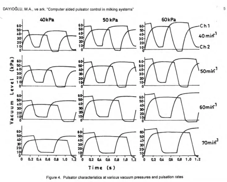
Pulsator characteristics in various vacuum pressures (40, 50 and 60 kPa), pulsator ratio (70 %) and pulsator rates (40, 50, 60 and 70 min-1) were giyen in Figure 4.
Figure 4 illustrates the changes in period of the expansion time and cycle time with respect to vacuum level for channel 1 and channel 2. As the vacuum level of two of teatcups falls down, another channel rises up, which indicates the expansion and compression phases of teatcups.
The rates of minimum vacuum phase (d) of channel 1 and 2 are giyen in Table 4. For example, the percentages of minimum vacuum phase of channel 1 and 2 are 20.3 % and 19.7 °A), respectively. The experimental resıılts indicated that the majority of minimum vacuum phase was higher than 15 %.
Conclusions
1. From the experimentai results, it is evident that the developed pulsation system is more effective than the conventional system.
2. The suitable pulsation characteristics could be adjusted depending on features of cows.
3. If there are a number of pulsators, they could be simultaneously and independently controlled from a central unit by changing set pulsation rate and set pulsator ratio
In all conditions, limping was found within values the giyen in standard
5. Pulsation characteristics were not dependent on the system pressure.
6. In all conditions, pulsation rate had a high
4 TAR1M BILIMLERI DERGISI 1999, Cilt 5, Sayı 2
Table 2. Set and measured values of pulsation rata and limping parameters in different vacuum pressures
P pulsaton rata PR set values of pulsator ratio (%), PR, measured pulsator ratio of channel 1 ( % ) , Limping (%) Set Values .._ - Vacuum Pressures (kPa) P L PR i- 40 45 50 55 60 P PR, I L PR, P PR, L P PR, I L PR, L .---. 40 50 5f
i
6'3 es 7'0 '75 39.8 39.8 39.8 39.8 39.7 39.8 49.5 54.4 59.4 54 4 69.4 74.5 ! T- CS T- T- e"-J 1 H: C-) C) C) C) CS 6 39.7 39.8 39.8 39.8 39.8 39.7 49.3 54.3 59.2 64.4 69.5 74.4 6 c> o c> CS ıı;1 •-• •-• C7 .C. ) 39.8 39.7 39.7 39.7 39.8 39.8 49.3 54.1 59.3 64.2 69.4 74.3 e- CS CS 07 CS CS CS CS CS C) 39.8 39.7 39.7 39.8 39.8 39.8 49.4 54.2 59,2 64.6 69.3 74.5 C> C) C: , c5 c> 6 c> 39.7 39.8 39.7 39.8 39.8 39.8 49.3 52.4 59.2 64.3 69.3 74.5 OS U 10 CU e- T- T-1 CS e- CS 6 c5 50 50 55 60 65 70 75 49.7 49.7 49.7 49.7 49.7_
49.7 49.3 54.1 59.1 64.3 69.3 74.3 c> co c> c> 6 c> c5 c> c> 6 1 49.7 49.7 49.8 49.8 49.8 49.7 49.1 54.1 59.0 64.0 69.2 74.3 0.2 0.1 0.2 0.3 0.0 0.1 49.8 49.8 49.7 49.7 49.7 49.7 49.3 54.1 59,2 64.2 69.0 74.3 C) C S T- CU ' TC C U CS C) d d ci 49.7 49.7 49.7 49.7 49.7 49.7 49.5 53.1 59.2 64.3 69.2 74.1 CS C» T- O C ı: : C) C) C) CS ci c>1 49.7 49.7 49.8 49.7 49.7 49.7 49.1 54.1 59.0 63.9 69.0 74.2 CS CD CS C ı CS C) CS K) ıs> İsJ ı• S I,I
60 I 50 55 60 65 70 75 59.6 59.6 50.6 59.6 ,i9.6 '59.6 49.1 54.1 59.0 64.1 69.1 74.3 --İ 11 P P c> P P 1 -■ ol 59.6 59.6 59.6 59.6 59.6 59.6 48.9 53.5 58.'3 64 .0 6'3.0 74.3 C7 T- T- CS C U CS CS C7 CS CS CS CS 59.6 59.6 59.6 59.6 59.6 59.6 49.1 53.8 58.7 63.9 69.1 74,0 c‘ : co co ci c> c5 c> ci 59.6 59.6 59.7 59.6 59,6 59.6 49.0 53.2 58.8 63.8 68.8 74.01
cs a co c ■ I o ,r ci 6 6 d ci 59.6 59 7 59.6 59.6 59.6 59.6 49.0 53.8 58.9 63.7 68.8 74.0 CS CU OS CU e- CS Ci Cj C) C) 6 6 70 CD US CS US C7 US US US CO CO;
69.5I
69.7 69.7 I 69.7 69.7 69.7 48.8 53.4 58.8 63.8 68.9 73.6 [CD C7 CS C S C) 61 k> ■ -■ 69.5 69.8 69.6 69.6 69.7 69.6 48.9 53.6 58.5 63.8 68.6 73.5 C> C4 CS CU CU US 1 Ci C. ) C) Ci CS CS 69.6 69.6 69.6 69.7 69.7 69.6 48.8 53.5 58.5 63.8 68.8 73.5 T- CU CU NI T- CS C) CS c5 c> c> 69.5 69.6 69.7 69.7 69.6 69.8 48.7 53.5 58.7 63.6 68.6 73.6 ICS C7 O CS CU C U CS CS C7 c5 ci c5 69.5 69.6 69.6 69.8 69.7 69.6 48.9 53.7 57.4 63.7 68.6 73 5CL
)
-• NO CS CS C) 1coTable 3 . Maximum vacuum phase of Ch.1 and maximum vacuum phase of Ch.2 values b, maximum vacuum phase of channel 1 (°/0), b2 maxirnum vacuum ph2ıse of channel 2 (°/0), and " values < 30 %
SE4 Value - 40 .- 45 Vacuum (kPa) 50 55 60 PR bi b2 b, b2 Id, b2 bi b2 bi b2 50 38.9 39.'1 37.8 38.3 36.4 36.6 35.2 35.3 34.6 34.4 55 44.5 44',.6 43.0 43.1 42.2 42.1 40.4 40.3 35.4 36.9 40 60 48,2 48.1 48.0 48.0 47.7 47.6 45.0 45.9 1 44.1 44.4 65 54.6 54.7 52.9 53.1 51.8 52.1 50.9 50.9 48.3 48.2 il 70 59.3 59.7 57.6 58.1 56.8 57.0 I 55.5 55.5 54.4 54.2 75 65.4 65.0 62.7 62.8 61.8 62.0 61.0 60.6 59.4 59.5 50 37.0 36.8 35.1 35.3 33.9 34.3 32.6 32.6 30.0 30.2 55 41.5 41.5 39.5 39.5 38.1 38.7 35.6 37.4 33.2 35.8 60 60 47.1 47.5 46.5 46.8 43.7 43.6 41.9 43.0 40.2 40.3 65 51.5 52.4 47.8 51.0 47.8 47.9 47.7 47.5 46.6 44.7 70 56.9 57.3 55.1 55.5 54.4 54.8 52.2 52.6 49.7 50.0 75 62 '2 62.3 60.2 60.7 59.9 59.7 56.8 57.4 55.2 55.3 50 33.7 34.4 31.4 32.1 30.3 31.2 28.7* 29.3* 28.6* 26.9* 55 4',.1 40.4 37.5 37.4 35.7 36.4 32.8 33.6 31.0 33.1 60 60 4 6.2 45.5 41.9 42.1 41.7 41.5 39.1 38.4 30.0 36.9 65 17.9 48.6 46.9 46.9 46.5 46.4 44.6 42.9 42.3 42.4 i 70 54.7 54.3 52.8 53.0 50.9 51.0 47.4 48.5 46.8 47.0 75 59.1 59.3 57.3 57.5 55.4 57.1 53.8 54.2 52.4 52.8 50 30.9 31.4 29 5 29.7* 28.2* 28.4 25 3 26.1 25.6* 25.0* 55 35.5 35.5 34.5 34.3 33.3 33.1 31.1 30.4 25.7* 29.2* 70 60 40.8 40.8 39.4 39.7 38.5 37.8 35.8 35.5 31.0 29.5* 65 46.1 46.6 45.8 46.4 43.1 41.8 40.7 40.7 36.7 36.3 70 51.0 51.3 48.2 49.6 46.7 47.0 45.9 46.4 43.9 43.2 75 56.3 56.7 54.2 55.3 52.3 54.2 50.5 50 8 47.1 49.2 . _____
50miffi
60mirri
70mm-1
İ O O -T- T O 0.2 0.4 0,6 OL 1.0 1.2 0 0.2 0.4 OL 0.8 1.0 1,2 0.2 0.4 0,6 0.8 1 .0 1.2T i me (s )
Figura 4. Pulsator characteristics at various vacuum pressures and pulsation rates
Table 4. Minimum vacuum phase of Ch.1 and minimum vacuum phase of Ch2. values, di minimum vacuum phase of channel 1 (%), d2 minimum vacuum phase of channel 1 (%), and *values either less than 15 % or less than 150 ms Set Values 40 45 Vacuum (kPa 50 55
11
60 P PR d, 44.0 39.1 34.0 29.0 24.0 19.0 d2 43.6 38.9 33.8 28.7 23.8 18.7 d, 43.6 38.8 33.8 28.7 23.5 18.5 d2 43.2 38.5 33.5 28.3 23.1 18.1 di 43.5 38.7 33.5 28.3 23.3 18.4 d2 43.0 38.3 33.0 28.0 23.0 18.0 di 42.8 38.1 33.0 27.9 22.9 17.8 d2 42.4 37.8 32.6 27.4 22.5 17.5 d, 42.6 38.1 32.9 27.6 22.6 17.4 d2 42.1 37.7 32.2 27.2 22.3 17.1 40 50 55 60 65 70 75 50 50 55 60 65 70 75 42.5 37.9 32.7 27.6 22.5 17.5 42.2 37.6 32.3 27.3 22.4 17.2 42.3 37,4 32.3 27.2 22.1 17.1 41.4 37.3 31.8 26.7 21.6 16.7 41.7 37.2 31.7 26.9 21.8 16.7 41.2 36.7 31.6 26.3 21.4 16.3 40.8 36.8 31.3 26.3 21.3 16.1 40.6 36.1 30.9 25.7 20.6 15.7 41.0 36.4 31.3 26.3 20.9 15 9 40.1 35.6 30.7 25.5 20.4 15.1 60 50 55 60 65 70 75 41.2 36.5 31.3 26.2 21.3 16.2 40.9 36.2 31.0 25.8 20.8 15.7 40.7 36.2 30.9 25.5 20.6 15.5 40.3 35.5 30.5 25.2 20.3 15.0 40.2 35.7 30.4 25.3 20.3 15.3 39.5 35.0 29.9 24.8 19.7 14.5* 39.5 35.2 30.0 24.8 19.7 14.5* 39.1 34.5 29.3 24.3 19.0 13.7* 39.3 34.7 29.9 24.5 19.4 14.2* 38.4 34.0 29.0 23.9 18.7 13.1* 70 50 55 60 65 70 75 39.5 35.1 30.1 24.9 19.7 14.9* 39.6 35.2 30.0 24.5 19.4 14.5* 39.2 34.7 29.6 24.4 19.0 14.2* 38.4 34.0 28.9 23.9 18.8 13.3* 38.6 34.1 29.1 23.8 18.8 13.7* 37.8 33.6 28.7 23.1 18.1 13.2* 37.9 33.4 28.6 23.3 18.21
12.9* 36.8 32.8 27.8 22.6 17.4 12.1*_
37.5 33.4 27.0 21.9 16.5_
11.5* 36.8 32.0 27.3 21.9 17.4 12.9*6 TARIM BILIMLERI DERGISI 1999, Cilt 5, Sayı 2
References
Cant, E. J. and Reitsma, S. Y.,1979. A Programmable Pulsator Control Unit for Miking Systems. Journal of Agricultural Engineering Research, 24: 331-336.
ISO 5707, 1996 Milking Machine Installations-Construction and Performance. International Standard.
ISO 3918, 1996. Milking Machine InstallationS, Vocabulary. International Standard.