Ugur Köklü
1,*, Okan Demir
2, Ahmet Avcı
2and Ayhan Etyemez
31Department of Mechanical Engineering, Karamanoglu Mehmetbey University,70100, Karaman, Turkey 2Department of Mechanical Engineering, University of Selcuk, Konya, Turkey
3Nikken, Istanbul, Turkey
(Manuscript Received May 31, 2016; Revised April 17, 2017; Accepted June 7, 2017)
--- Abstract
Functionally graded composite (FGC) materials are categorized as advanced materials that display different thermal and mechanical responses compared with well-known composites, such as carbon fiber or glass fiber-reinforced composites. This paper presents the ex-perimental results for the drilling of three materials, namely glass/epoxy, carbon/epoxy, and FGC material. FGC was compared with carbon and glass/epoxy composites in terms of thrust force, delamination factor, diameter of hole, and roundness during drilling. This study illustrated that the drilling performance of FGC is considerably more complicated than that of more common composite materials, such as glass/epoxy and carbon/epoxy. Delamination factor at the exit of hole during drilling of FGC was mainly affected by the material placed at the exit of the hole. The proposed cutting parameters and drill geometries to minimize the occurrence of delamination during drilling of carbon/epoxy and glass/epoxy apparently does not meet the expectation in drilling FGC.
Keywords: Composite; Damage; Delamination; Drilling; Roundness
---
1. Introduction
Drilling process is needed to build a load-carrying structure of composite materials [1]. Conventional drilling process is an important final process for components made of composites [2]. Drilling-induced delamination and thermal damage of composite materials are serious problems encountered during drilling of composite materials, especially the high-value components used in aviation industry [3]. Thus, studies have been conducted on drilling processes of various composite materials to determine the parameter that causes damages [4, 5]. During drilling, delamination occurring at the entrance and exit of a created hole is affected by various parameters [6]; therefore, researchers also investigated thrust force and torque and determined the interrelationship among these parameters [7-10]. Moreover, geometry of drill bit [11-13], cutting condi-tions [14], and properties of work material and coating [15], have been the subject of studies to elucidate their effects on delamination [16]. Majority of these studies have focused on either carbon fiber- or glass fiber-reinforced composite mate-rials [16, 17]. Studies in the areas of material science and en-gineering or in the industrial realm have considered other
ad-vanced composite materials, although the machining commu-nity has not yet extensively investigated the drilling perform-ance of such advperform-anced composite materials. One of the ad-vanced composite materials that has shown great development is Functionally graded composites (FGCs). These materials are gaining widespread applications in various branches of engineering technology [18]; for instance, they contribute in potential reduction of in-plane and through-the-thickness transverse stresses and in improvement of thermal properties and high toughness [18]. The elimination of damage occurring at the entrance or exit of holes produced in these FGC materi-als under severe working conditions has gained a considerable interest. However, to our best knowledge, no comprehensive study on conventional drilling process of FGC has been con-ducted. Thus, this study is the first comprehensive investiga-tion on the drilling performance of FGC materials; moreover, this study compares the FGC materials with carbon/epoxy and glass/epoxy composite in terms of thrust force, delamination, hole diameter, and roundness.
2. Materials & methods
The composites used in this study are FGC, carbon/epoxy, and glass/epoxy composite materials. FGC materials were produced using plain weave glass (Hexcel (USA)) and carbon fiber fabrics with a tex number of 200 (Interglas (Germany)),
*Corresponding author. Tel.: +90 506 234 4820, Fax.: +90 338 226 2214
E-mail address: [email protected]
† Recommended by Editor Chongdu Cho
as well as epoxy resin (L160) and hardener (H160) obtained from Momentive (USA). Glass and carbon fiber fabrics were cut into desired size and then cleaned with acetone to remove residual dust; the fabrics were dried at room temperature for 12 h. Epoxy resin and hardener were mixed mechanically for approximately 5 min at 100:25 ratio according to manufac-turer’s recommendation. Nylon mold release film, bottom distribution mesh, bottom peel ply, fiber fabrics (30 layers), upper peel ply, and upper distribution mesh were sequentially laid onto a steel plate. Inlet and outlet pipes and connections were installed and then covered with vacuum bag and sealed. The air in the system was evacuated with a vacuum pump up to –0.8 bar pressure. The inlet port was opened and resin was infused into the fabrics by using vacuum. After infusion was completed, the inlet and outlet ports were clamped. The fab-rics were cured at 70 °C for 1 h and then post-cured at 110 °C for 4 h. Finally, the peel plies were removed and the produced fabrics were cut into the sizes required for the drilling tests.
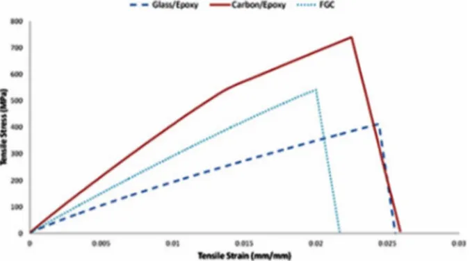
The specimens were subjected to tensile tests according to ASTM standard D3039/D3039M – 14 [19] by using Instron 8801 Universal Testing Machine at a constant head speed of 2 mm/min at room temperature. The dimensions of the speci-men was 250 mm × 25 mm × 5 mm. The results are presented in Fig. 1, which shows that the ultimate tensile strength of the FGCs lies between that of glass fiber composite and carbon fiber composite. This phenomenon was observed either be-cause of a negative hybrid effect on strain or bebe-cause of de-lamination failure promoted by elastic modulus mismatch between glass and carbon fibers.
The FGC plate used in this study was 5 mm thick. FGC consists of two phases, namely, carbon fiber and glass fiber. One side consisted of pure carbon/epoxy, whereas the other side consisted of glass/epoxy (Fig. 2). From one side to the other, the number of carbon fiber layer increases, whereas the number of glass fiber layer decreases. The direction of the plate is the key parameter that determines the mechanical properties of this material.
Fig. 3 shows the edge radius measurement and drilling ex-perimental setup measurements. The edge radii of drill bits were approximately 16 µm as measured by ZeGage 3D Opti-cal Profiler. Drilling experiments were conducted using a
CNC machining center that has a maximum spindle speed of 10000 rev/min and a power of 12 kW. No coolant nor lubri-cant was used during the drilling process. The carbide drill bit used in these experiments has two angles on the cutting edge, namely, 90° and 110° (Fig. 3(b)).
Kistler type 9257B commercial piezoelectric dynamometer was used to measure thrust forces generated during the drilling experiments (Fig. 4). Only the thrust force, which is the force in the Z direction (Fz), was considered in the drilling operation. The maximum thrust force was taken from the drilled area where the thrust forces were regular and far from the entry and exit influences of hole. The cutting force signals were filtered by a smoothing filter.
Leica DM2700M optical microscopy was used to measure damage around the produced hole. Based on the measured values, delamination factor was formulated as follows [20]:
max 0 d D F D = (1)
where Dmax is the maximum diameter of the damaged zone,
and D0 is the hole diameter. Fig. 5 shows the schematic of
Dmax and D0. Roundness of drilled holes was measured using a
coordinate measuring machine (DEA Mistral CMM). Fig. 1. Stress-strain diagram for glass/epoxy, carbon/epoxy, and
Func-tionally graded composite (FGC).
Fig. 2. Schematic of workpiece positions (glass exit and carbon exit) during drilling of functionally graded composite materials.
(a) (b) (c) Fig. 3. (a) Experimental setup; (b) drill bit used in the experiments; (c) edge radius measurement.
3. Results and discussions
Fig. 6 shows the thrust forces recorded when drilling vari-ous composite materials. The maximum thrust force was used to evaluate the variation in thrust force in the experiments. Fig. 7 shows the influence of feed rate on the thrust force recorded when drilling FGC materials, glass/epoxy, and carbon/epoxy. During the drilling process for all composites, increased feed rate resulted in increased thrust force, consistent with previous findings [10, 21]. Based on the performances of the different composite materials, the largest thrust force was recorded when drilling carbon/epoxy composite, whereas the smallest thrust force was found when drilling glass/epoxy composite at different feeding rates.
Similar result was observed by Santhanakrishnam et al. [22]. The force values recorded when drilling FGC lie between those of carbon/epoxy and glass/epoxy (Fig. 7). This response is consistent with the stress-strain response of FGC (Fig. 1), wherein its ultimate tensile strength also lies between those of glass/epoxy and carbon/epoxy composite material. A direct relationship exists between stress-strain response of composite material and the force generated when drilling composite ma-terial. When the ultimate tensile strength of the composite increases, the required force to drill the material also increases. In addition to the investigation on the drilling performance of the given work material when a single hole is produced, the variation resulting from the number of drilled holes is also recorded and presented in this study.
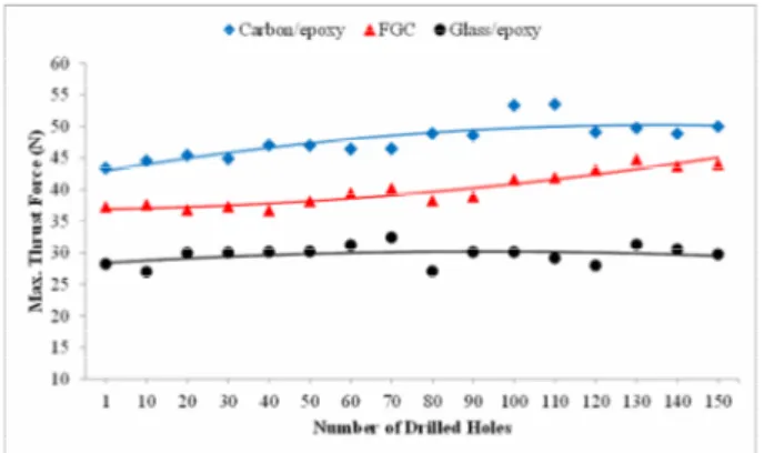
Fig. 8 shows the recorded thrust force values when 150 holes were produced at constant spindle speed and feed rate of 5000 rpm and 0.04 mm/rev, respectively. Although the number of drilled holes was increased, the trend for the recorded thrust force does not substantially change. This result is mainly due to the fact that the used cutting tools in these series of experi-ments do not show substantial wear over time; consequently, force response does not change with the increase in number of drilled holes. However, when drilling FGC material, the thrust force increases with increased number of drilled holes.
Among the defects caused by drilling, delamination is one of the most serious defects because it is responsible for the rejection of approximately 60 % of the components used in aircraft industry. Delamination results in poor assembly toler-ance and reduces the structural integrity of the work material [23]. Damages occurring at the exit of a hole is one of the significant issues researchers have been trying to resolve as Fig. 5. Schematic of D0 and Dmax. Fig. 6. Thrust force curve obtained when drilling various composites at
5000 rpm and 0.04 mm/rev feed rate.
Fig. 7. Recorded maximum thrust force as a function of feed rate when drilling various composite materials (5000 rpm spindle speed).
Fig. 8. Effects of the number of drilled holes on variation in thrust force when drilling composite materials (5000 rpm and 0.04 mm/rev).
they directly affect the durability of composite laminates, which are subjected to various loads when in use. This study aims to observe delamination response of FGC. The proposed solution in literature to eliminate delamination can be useful either in CFRP or GFRP [16, 17], as discussed in the introduc-tion. However, the delamination issue in drilling of FGC is apparently considerably more complicated. The material con-stituting the outer layer determines the delamination response of FGC as a result of the drilling process, and this phenome-non is one of the important findings of this study. Fig. 9 shows the images taken from the exit hole of FGC material after creating the 1st, 75th and 150th hole. A large difference be-tween carbon/epoxy and glass/epoxy is evident. When the exit side consists of carbon epoxy, the damage is minimal; how-ever, when the exit side consists of glass epoxy, a considerable damage occurs. This phenomenon makes the problem consid-erably more complicated compared with the delamination issue in drilling of well-known composite materials, such as CFRP or GFRP.
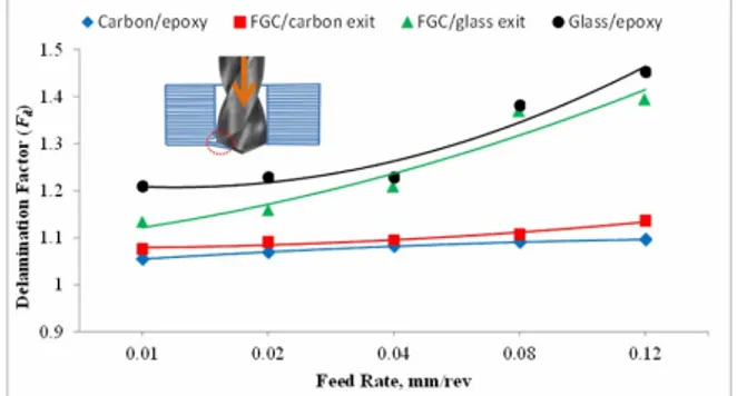
Fig. 10 shows the delamination factor resulting from vari-ous feed rates in drilling carbon/epoxy, glass/epoxy, FGC/carbon exit, and FGC/glass exit. The delamination factor increases with increased feed rate and number of drilled holes, consistent with the results of Krishnaraj et al. and Davim et al. [23, 24]. Moreover, a substantial difference is evident between carbon/epoxy and glass/epoxy. The drilling process for car-bon/epoxy composite results in a considerably smaller de-lamination factor compared with the drilling process for
glass/epoxy composite at a constant feed rate. This phenome-non should be related to the fracture response of carbon and glass fiber. This result shows that in addition to the role of selected cutting parameters, work materials themselves deter-mine the delamination factor.
Moreover, in drilling FGC, the material on the exit side de-termines the delamination factor. Experimental data support this argument (Fig. 9). When the exit side of FGC consists of glass/epoxy, the delamination factor is extremely larger than that of the exit side consisting of carbon/epoxy. Both FGC and carbon/epoxy composites consist of 30 layers (Fig. 2). While carbon/epoxy composite is entirely composed of carbon fiber, the last five layers of FGC/carbon exit consist of carbon fiber. Given this arrangement, carbon/epoxy composite has a more compact structure and is more rigid than FGC. Given that carbon/epoxy composite is more resistant due to its being compact and rigid against thrust force and bending stress dur-ing drilldur-ing compared with FGC, less delamination damage occurs in carbon/epoxy composite than in FGC/carbon exit.
This trend does not change as the number of drilled holes increases (Fig. 11). However, as the number of drilled holes increases, delamination factor of FGC/carbon side considera-bly increases compared with that of carbon epoxy composite. These changes can be attributed to the abrasive nature of car-bon fiber and the worn tool; these factors eventually increases the delamination factor as the number of drilled holes in-creases. As shown in Fig. 11, after 50 holes were drilled, the difference between carbon/epoxy and FGC carbon exit has become obvious. This finding should be related to the change in edge radius of drill bit as the number of holes increases. The fundamental reason causing delamination factor is tool wear, which increases with increased number of holes. With the increase in tool wear, a greater amount of cutting force is required to drill the material, resulting in increased bending stress on the material. For these reasons, a greater delamina-tion damage occurs on the FGC/carbon exit, the last five lay-ers of which consist of carbon.
Hole diameter error corresponds to a dimensional tolerance that controls by how much a hole size deviates from the ideal dimensions. For precise assembly of components, the hole generated should display a minimum error. It is most vital Fig. 11. Effects of the number of drilled holes on variation in delami-nation factor during drilling (5000 rpm and 0.04 mm/rev).
Fig. 9. Photograph of exit hole of functionally graded composite (5000 rpm spindle speed and 0.04 mm/rev feed rate).
Fig. 10. Delamination factor as a function of feed rate in drilling vari-ous composite materials (5000 rpm spindle speed).
where error in dimension caused failure of human life [25]. Hole diameter is another measured parameter affected by the number of drilled holes and by the properties of work materi-als. Although the nominal hole size is 3.94 mm, the measured diameter of the first hole is apparently larger than the nominal hole size in all drilled composites, namely glass/epoxy, car-bon/epoxy, and FGC (Fig. 12). However, it should be noted that the diameter of hole produced from all four composite is approximately 3.95, which is the expected deviation consider-ing the thermal expansion properties of these material durconsider-ing the drilling process. When the number of drilled holes in-creases, hole diameter when drilling carbon epoxy and FGC substantially changes. In addition to the thermal expansion properties, the diameter of drilled bit over the number of drill holes also changes due to the abrasive nature of the composite materials; thus, when the number of drilled holes increases, the measured diameter of the produced hole approaches the nominal hole diameter. Dimensional changes in drill bit play a dominant role on the thermal expansion response of car-bon/epoxy and FGC materials when they are drilled. The hole diameter decreases with the increase in number of drilled holes, consistent with the results of Shyha et al. [26].
In dimensional metrology, geometric form is a very impor-tant feature considered in quality control of products. Round-ness is an essential geometrical feature especially for rotating parts in aerospace, nuclear reactors and automotive applica-tions; thus, accurate and precise measurement with minimum deviation for this parameter is necessary [27]. In addition, roundness measurement is a critical matter in quality control and inspection [28].
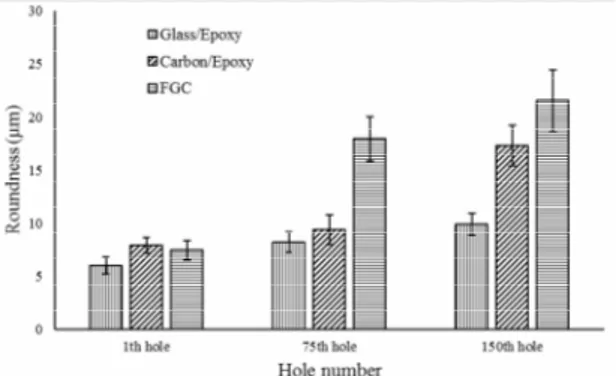
By measuring roundness, it is possible to have information on hole shape, definitely how the circular cross-section of a hole approximates to an accurate circle [29]. Fig. 13 shows the measured deviation in roundness of the produced holes. Mini-mum deviation was observed in the first drilled holes; how-ever, deviation increases with increased number of drilled holes. A similar trend was reported by Bhattacharyya et al. and Faria et al. [30, 31].
Glass epoxy displays the smallest deviation, whereas the maximum deviations were observed when drilling FGC. This
observation is mainly due to the structure of FGC, which con-sists of carbon fibers and glass fibers, each displays different response to stress and generated temperature during drilling; as a result, roundness largely varies, although the deviation is still less than 20 µm in the majority of the drilled holes. Due to the nature of the drilling process, as the number of drilled holes increases, cutting edge becomes rounded and thus the deformation process considerably worsens; consequently, the roundness of the holes shows a considerably large deviation. When drilling FGC material, the thrust force (Fig. 8) increases with increasing number of drilled hole. The main reason for this increase in force is cutting tool wear. The increase in roundness is attributable to the increasing cutting edge radius of the cutting tool. Moreover, elastic modulus of carbon/epoxy is higher than that of glass/epoxy. Cutting force and tempera-ture during drilling vary due to these featempera-tures. Furthermore, the strengths of the different layers vary during drilling. Given that FGC composite plate consists of two different materials, more damages, such as separation between layers, were ob-served in FGC than in carbon/epoxy and glass/epoxy. There-fore, roundness is increased in FGC.
4. Conclusions
This study demonstrates the performance of FGC and com-pares its drilling performance with that of carbon and glass/epoxy composites in terms of thrust force, delamination factor, hole diameter, and roundness. Compared with drilling process for glass/epoxy and carbon/epoxy composite, that for FGC is considerably more difficult particularly when delami-nation factor is taken into account. The delamidelami-nation factor of functionally graded materials mainly depends on the material placed at the top and bottom of a composite plate; thus, en-trance and exit delamination factor for the produced holes can show large differ. Based on the findings of this study, the cut-ting parameters and drill bits used in well-known composite materials is not recommended for drilling of FGC. Further studies are needed to determine the appropriate cutting condi-tions for drilling of FGC materials and ultimately to fully con-trol the drilling process for FGC.
Fig. 13. Deviation in the measured roundness of the 1st, 75th and 150 th holes produced from drilling of glass/epoxy, carbon/epoxy, and functionally graded composite.
Fig. 12. Measured diameter from the exit of 1st, 75th and 150th holes produced from drilling of glass/epoxy, carbon/epoxy, and functionally graded composite.
[2] D. Liu, Y. Tang and W. L. Cong, A review of mechanical drilling for composite laminates, Composite Structures, 94 (4) (2012) 1265-1279.
[3] N. Li, Y. Li, J. Zhou, Y. He and X. Hao, Drilling delamina-tion and thermal damage of carbon nanotube/carbon fiber re-inforced epoxy composites processed by microwave curing,
International Journal of Machine Tools and Manufacture,
97 (2015) 11-17.
[4] S. Singh, Effect of modified drill point geometry on drilling quality characteristics of Metal matrix composite (MMCs),
Journal of Mechanical Science and Technology, 30 (6)
(2016) 2691-2698.
[5] X. Qin, B. Wang, G. Wang, H. Li, Y. Jiang and X. Zhang, Delamination analysis of the helical milling of carbon fiber-reinforced plastics by using the artificial neural network model, Journal of Mechanical Science and Technology, 28 (2) (2014) 713-719.
[6] J. P. Davim and P. Reis, Study of delamination in drilling Carbon fiber reinforced plastics (CFRP) using design ex-periments, Composite Structures, 59 (4) (2003) 481-487. [7] Y. Karpat, O. Bahtiyar, B. Değer and B. Kaftanoğlu, A
mechanistic approach to investigate drilling of UD-CFRP laminates with PCD drills, CIRP Annals-Manufacturing
Technology, 63 (1) (2014) 81-84.
[8] S. J. Ha, K. B. Kim, J. K. Yang and M. W. Cho, Influence of cutting temperature on carbon fiber-reinforced plastic com-posites in high-speed machining, Journal of Mechanical
Sci-ence and Technology, 31 (4) (2017) 1861-1867.
[9] M. Okada, N. Asakawa, Y. Fujita and M. Nikawa, Cutting characteristics of twist drill having cutting edges for drilling and reaming, Journal of Mechanical Science and
Technol-ogy, 28 (5) (2014) 1951-1959.
[10] C. C. Tsao, Thrust force and delamination of core-saw drill during drilling of Carbon fiber reinforced plastics (CFRP),
The International Journal of Advanced Manufacturing Technology, 37 (2008) 23-28.
[11] C. C. Tsao and H. Hocheng, Taguchi analysis of delamina-tion associated with various drill bits in drilling of composite material, International Journal of Machine Tools and
Manu-facture, 44 (10) (2004) 1085-1090.
[12] H. Hocheng and C. C. Tsao, Comprehensive analysis of delamination in drilling of composite materials with various drill bits, Journal of Materials Processing Technology, 140 (1-3) (2003) 335-339.
[13] W. C. Chen, Some experimental investigations in the drill-ing of Carbon fiber-reinforced plastic (CFRP) composite laminates, International Journal of Machine Tools and
Manufacture, 37 (8) (1997) 1097-1108.
[14] T. Xia, Y. Kaynak, C. Arvin and I. S. Jawahir, Cryogenic
and new nano-coated tool on drilling performance of CFRP/Aluminium sandwich, Composites: Part B, 43 (3) (2012) 1480-1488.
[16] D. Kumar and K. K. Singh, An approach towards damage free machining of CFRP and GFRP composite material: A review, Advanced Composite Materials, 24 (1) (2015) 49-63. [17] A. M. Abrao, P. E. Faria, J. C. Rubio, P. Reis and J. P.
Davim, Drilling of fiber reinforced plastics: A review, Journal
of Materials Processing Technology, 186 (1-3) (2007) 1-7.
[18] D. K. Jha, T. Kant and R. K. Singh, Critical review of re-cent research on functionally graded plates, Composite
Structures, 96 (2013) 833-849.
[19] ASTM, D:3039/D3039M-14, Standard test method for
tensile properties of polymer matrix composite materials.
[20] J. Babu, N. P. Alex, K. P. Mohan, J. Philip and J. P. Davim, Examination and modification of equivalent delamination factor for assessment of high speed drilling, Journal of
Me-chanical Science and Technology, 30 (11) (2016) 5159-5165.
[21] K. Ogawa, E. Aoyama, H. Inoue, T. Hirogaki, H. Nobe, Y. Kitahara, T. Katayama and M. Gunjima, Investigation on cutting mechanism in small diameter drilling for GFRP (thrust force and surface roughness at drilled hole wall),
Composite Structures, 38 (1997) 343-350.
[22] G. Santhanakrishnan, R. Krishnamurthy and S. K. Malhotra, Machinability characteristics of fibre reinforced plastics composites, Journal of Mechanical Working Technology, 17 (1988) 195-204.
[23] V. Krishnaraj, A. Prabukarthi, A. Ramanathan, N. Elang-hovan, M. S. Kumar, R. Zitoune and J. P. Davim, Optimiza-tion of machining parameters at high speed drilling of Car-bon fiber reinforced plastic (CFRP) laminates, Composites
Part B: Engineering, 43 (2012) 1791-1799.
[24] J. P. Davim, J. C. Rubio and A. M. Abrao, A novel approach based on digital image analysis to evaluate the delamination factor after drilling composite laminates, Composites Science
and Technology, 67 (9) (2007) 1939-1945.
[25] A. Kamboj, S. Kumar and H. Singh, Burr height and hole diameter error minimization in drilling of AL6063/15%/SiC composites using HSS step drills, Journal of Mechanical
Science and Technology, 29 (7) (2015) 2837-2846.
[26] I. S. Shyha, S. L. Soo, D. Aspinwall and S. Bradley, Effect of laminate configuration and feed rate on cutting perform-ance when drilling holes in carbon fibre reinforced plastic composites, Journal of Materials Processing Technology, 210 (2010) 1023-1034.
[27] S. H. R. Ali, Method of optimal measurement strategy for ultra-high-precision machine in roundness nanometrology,
Int. Journal on Smart Sensing and Intelligent Systems, 8
drilling in Kevlar composites, Composites Science and
Technology, 58 (1998) 267-283.
[31] P. E. Faria, J. C. Campos Rubio, A. M. Abrao and J. P. Davim, Dimensional and geometric deviations induced by drilling of polymeric composite, Journal of Reinforced
Plas-tics and Composites, 28 (2009) 2353-2363.
Ugur Köklü graduated from Dumlupi-nar University, Turkey, in 2001. He received his M.S. degree from Dumlu-pinar University in 2005 and his Ph.D. degree from Marmara University in 2010. Dr. Köklü is currently an Associ-ate Professor at the Engineering Faculty at Karamanoglu Mehmetbey University in Karaman, Turkey. His research interest includes machining.
Ahmet Avcı received his Ph.D. from Selcuk University (SU), Turkey and is currently Professor at the Department of Mechanical Engineering in SU. His research areas include nanocomposites, fracture mechanics, and fatigue of struc-tures.
Ayhan Etyemez was born in October 1971 in Turkey. He received B.S., M.S. and Ph.D. from the Mechanical Depart-ment of Marmara University, Turkey, in 1993, 1996, and 2003, respectively. His research interest includes metal cutting.