Procedia CIRP 1 ( 2012 ) 460 – 465
2212-8271 © 2012 The Authors. Published by Elsevier B.V. Selection and/or peer-review under responsibility of Professor Konrad Wegener http://dx.doi.org/ 10.1016/j.procir.2012.04.082
5
thCIRP Conference on High Performance Cutting 2012
Milling Force Modelling of Multidirectional Carbon Fiber
Reinforced Polymer Laminates
Yi÷it Karpat
a*, Onur Bahtiyar
b, Burak De÷er
baBilkent University, Department of Industrial Engineering, Ankara 06800 Turkey bTurkish Aerospace Industries Inc., Ankara 06980 Turkey
* Corresponding author. Tel.: +90-312-2902263; fax: +90-312-266-4054.E-mail address: [email protected].
Abstract
Carbon fiber reinforced polymer (CFRP) usage in the aerospace industry has been steadily increasing due to its superior material properties such as high strength, low weight, high resistance to corrosion, and a low thermal expansion coefficient. In addition, CFRP parts are produced near-net-shape, a process that eliminates rough machining operations. However, machining operations such as drilling, side milling, and slotting are still necessary to give the CFRP parts their final shape. A majority of the studies on machining of CFRP laminates are on drilling. The number of studies on milling of CFRPs is quite limited. In this study, a mechanistic cutting force model for milling CFRPs is proposed based on experimentally collected cutting force data during slot milling of unidirectional CFRP laminates using a polycrystalline diamond cutter. Cutting force coefficients in radial and tangential directions are calculated as a function of fiber cutting angle. The mechanistic model is shown to be capable of predicting cutting forces during milling of multidirectional CFRP laminates and capable of investigating stability of machining.
© 2012 Published by Elsevier BV. Selection and/or peer-review under responsibility of Prof. Konrad Wegener
Keywords: Machining; milling; composite; stability
1. Introduction
The popularity of carbon fiber reinforced polymers (CFRP) in the aerospace industry has been increasing thanks to their desirable mechanical and physical properties. They show high resistance to corrosion and have low thermal expansion coefficient. In addition, they are light and durable, properties that allow manufacturers to produce lighter airplanes that consume less fuel.
Anisotropic and inhomogeneous material properties create problems during machining of CFRPs. Since material properties of CFRPs depend on the fiber direction of the laminate, machining forces and machined surface quality may change depending on the direction of cutting. The chip formation mechanism is shown to be mostly brittle fractures while machining FRPs, which makes them quite different from metals. The highly abrasive nature of the carbon fibers and the low thermal conductivity of the resin matrix results in
rapid tool wear, even when diamond coated carbide and polycrystalline diamond cutting tools are used. Because of its laminated structure, plies are subject to separation (i.e. delamination) due to cutting forces during machining. The tool wear must be controlled closely since it increases cutting forces, which in turn increases the likelihood of inducing delamination. In addition, due to machining of thick structural CFRP parts, stability of milling may be an issue. Cutting force modelling is a crucial step towards this aim.
In the literature, experimental, analytical, and finite element modelling techniques have been used to study the chip formation mechanism in machining CFRPs. Detailed literature reviews on machining composite materials can be found in [1, 2]. Koplev [3] used a shaping machine to conduct orthogonal cutting tests on CFRP. He studied chip formation mechanisms and the effect of fiber direction on the surface roughness, finding that surface quality depends on the fiber direction and that when fibers were parallel to cutting direction it
© 2012 The Authors. Published by Elsevier B.V. Selection and/or peer-review under responsibility of Professor Konrad Wegener
Open access under CC BY-NC-ND license.
yielded a good surface compared to perpendicular fibers. Chips that were collected during Koplev's experiments supported the observation of brittle fracturing of the fibers. Koplev et al. [4] also studied the effect of tool geometry on machining and observed the positive influence of increasing clearance angle on machining forces. Hocheng et al. [5] conducted milling tests on CFRPs, and chip formation, surface roughness, and cutting forces were observed. He categorized chips as powder-like and ribbon-like, produced as a result of fracture and buckling of fibers, respectively. His results supported the findings of Koplev [4]. Wang et al. [6] conducted orthogonal cutting experiments on unidirectional laminates and observed greater thrust forces than cutting forces due to elastic recovery of the fibers. They also observed that the tool rake angle changes the chip formation mechanism and that the cutting speed has no significant effect on cutting forces. Wang et al. [7] conducted similar tests on multidirectional laminates, consisting of unidirectional laminates with different fiber directions. They concluded that each layer behaves as an independent laminate, and the superposition principle can be used to calculate cutting forces.
Studies of milling CFRPs are somewhat limited compared to drilling. Kalla et al. [8] proposed a mechanistic machining model for CFRPs. A neural network model was used to estimate cutting and rubbing force coefficients in radial and tangential directions. They calculated machining forces for low radial immersion upmilling with flat end mill with helical teeth. They obtained good results for unidirectional laminates but less than desirable results for multidirectional laminates. Jahromi and Bahr [9] proposed a theoretical model based on material mechanical properties of the FRPs. Many factors are shown to affect the mechanical properties of the FRPs carbon fiber properties including carbon fiber diameter, volumetric ratio of carbon fibers, curing conditions etc. They concluded that their model works well when
fracture plane angle is between 90° and 180°. Recently,
Hintze et al. [10] investigated machining CFRPs during slot milling experiments and observed that occurrence of delamination is closely related to tool wear and top layer fiber cutting angle. Lopez de Lacalle et al. [11] studied the performance of multi-tooth cutting tools during the trimming process of CFRPs. They found that the performance of multi-tooth cutting tools with TiAlN coating was superior to straight edge PCD tools for finishing operations.
In this study, a PCD tool is selected to investigate cutting forces during milling of unidirectional CFRP laminates. A mechanistic force model is proposed based on experimental investigation. The proposed model is
then validated on multidirectional CFRP laminates and results are discussed. An impact hammer test is used to calculate the dynamic properties of the machine tool and milling stability is investigated.
2. Milling of Unidirectional Composite Laminates
Fiber direction (θ) of the laminate is calculated by
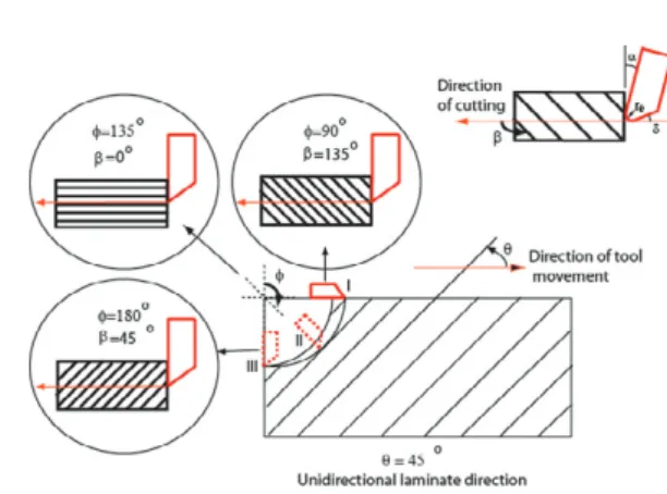
considering tool movement direction and orientation of the fibers in the laminate. The fiber direction angle is measured counter clockwise [10] with reference to the tool movement direction as explained in Figure 1.
Depending on the fiber direction (θ) of the laminate, the
interaction between the tool and the material changes as the cutting tool rotates during milling. Hence, the cutting tool interacts with different fiber directions as it rotates. This interaction angle is named as the fiber cutting angle (ȕ). It is also explained in Figure 1. Figure 1 shows fiber cutting angles calculated at three different locations (I,
II, and III) for a 45° fiber direction laminate. Fiber
cutting angle (ȕ) can be represented with Equation 1 by
considering the fiber direction of the laminate (θ) and
the tool rotation angle (φ).
(
,180)
mod then 180 if , φ θ β β β βφθ = + ≥ = (1)Figure 1. Fiber cutting angle (ȕ) as a function of tool rotation angle (φ) and fiber direction of the laminate (θ)
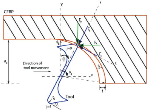
Figure 2 represents cutting forces acting on the tool
during the milling process where tangential forces (Ft)
are directed in the opposite direction of the cutting, and
radial forces (Fr) act towards the centre of the tool.
Mechanistic force modelling approach [12] can be used to calculate radial and tangential forces based on material and tool properties. By using this approach, cutting force coefficients in tangential and radial directions as a function of fiber cutting angle can be obtained through milling tests. Cutting force coefficients
Ktc and Krc represent materials’ resistance to machining
in tangential and radial directions. Additional forces due to rubbing between the tool (flank face and edge radius) and the work material can also be included in force
modelling by considering rubbing force coefficients (Kte
and Kre) in tangential and radial directions. Rake angle
(Į), clearance angle (δ), edge radius (re), and tool
material properties influence cutting force coefficients.
Figure 2. Milling forces acting on the tool.
Equation 2 represents cutting forces in x-y direction
for a tool with zero helix (γ) and zero rake angle (Į). In
Equation 2, ap is the axial depth of cut and h is
instantaneous chip thickness [13]. Chip thickness (h) can be calculated by considering feed (f) and tool rotation
angle (φ) as shown in Equation 2. A circular tool path is
assumed while calculating the chip thickness. ( ) ( ) ( )( )
¦
− = ¸ ¸ ¹ · ¨ ¨ © § » ¼ º « ¬ ª » ¼ º « ¬ ª − − + » ¼ º « ¬ ª » ¼ º « ¬ ª − − = » ¼ º « ¬ ª 1 0 sin cos sin cos cos sin sin cos s j re te rc tc j j p y x K K K K h g a F F β β φ φ φ φ β β φ φ φ φ( )
j j f h = sinφ (2)In Equation 2, the index j represents the number of teeth on the tool. In order to calculate total milling forces, the number of teeth on the cutter (s) and the
radial depth of cut (ae) must also be known. This
information is used to calculate entry (φs) and exit (φe)
angles. Depending on these angles, some teeth may not be in contact with the material during milling, so those cases are excluded from force analysis by considering
the instantaneous location of the tooth (φj(t)) with
respect to entry (φs) and exit (φe) angles. A control
function (g) is defined in order to check whether the tool is in the cut or not as in Equation 3.
s j s j j 0,1,.., 2 0− = =φ π φ
( )
¿ ¾ ½ ¯ ® ≤ ≤ > = elsewhere h g s j e j j j 0 0 and 1 φ φ φ φ (3)3. Experimental Setup and Milling Force Measurements
Experimental studies were conducted on a 24 kW Dörries Scharmann Technologies 5-axis machining center with maximum 24,000 rpm rotational speed. Two
different types of unidirectional CFRP laminates (0° and
45° fiber directions) consisting of 30 layers were
produced for slot milling experiments. CFRP laminates were 10 mm in thickness. These laminates allow
experiments to be conducted on 90° and 135° fiber
directions by changing the milling direction. The physical and mechanical properties of the CFRP laminates used in this study are given in Table 1.
Table 1. Material properties of CFRP laminates Material Fiber Vol. (%v/v) Strength (MPa) Modulus (GPa) Density (g/cm3) CFRP1 59 2690 165 1.58
1Mechanical properties are the room temperature 0Û tensile properties of the laminate.
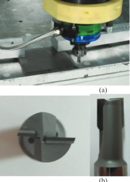
The machining forces during milling experiments were measured by a Kistler 9123 rotating dynamometer and its Kistler 5223 charge amplifier. The cutting force data were collected using a data acquisition system and processed on a personal computer. Torque and milling forces in x, y, z directions were recorded with a sampling rate of 25 kHz. Cutting force measurements are repeated three times to check the consistency of the measurements. During force measurements, the x-axis of the dynamometer is aligned with radial direction of the milling tool. Unidirectional CFRP plates were tightly secured to the machine base as shown in Figure 3(a). This study employs polycrystalline diamond (PCD) milling tools specially designed for CFRP machining. The PCD tool (Schwegler) used in slotting experiments has two teeth with zero helix and zero rake angles as shown in Figure 3(b). PCD tool has 20º clearance angle and PCD tips are brazed on the carbide tool body. The diameter of the tool is 10 mm. Cutting speed is kept constant in experiments since its influence on cutting forces is observed to be insignificant. Feed per tooth values are take as 0.02, 0.026, and 0.03 mm/tooth. Experiments were conducted under wet conditions in order to avoid carbon powders. Milling force measurements in x, y, and z directions with respect to
the reference system of the dynamometer for 0° and 45°
fiber directions are given in Figure 4. Experiments were
laminates. Due to the zero helix angle on the cutter,
forces in vertical direction (Fz) were quite small in all
milling cases. Keeping vertical forces small is an important consideration due to the delamination issue. Milling tests were conducted under stable machining conditions.
(a)
(b)
Figure 3. Details related to slot milling experiments: (a) Experimental test setup, (b) Zero rake and helix angle PCD cutting tool
6.48 6.49 6.5 6.51 6.52 6.53 6.54 6.55 6.56 6.57 -300 -200 -100 0 100 200 300 Time (s) M illin g F o rc e s ( F x, F y, F z) ( N ) Fx Fy Fz Fiber Direction 0 deg (a) 7.74 7.76 7.78 7.8 7.82 -250 -200 -150 -100 -50 0 50 100 150 200 250 Time (s) M illin g F o rc e s ( F x, F y, F z) ( N ) Fx Fy Fz Fiber Direction 45 deg (b)
Figure 4. Unfiltered force data for (a) 0º, (b) 45º fiber direction CFRP laminates.
Force measurements (Fx) in radial direction are
significantly higher than tangential force measurements
(Fy). Peak radial forces recorded on 0º fiber direction is
observed to be higher than radial forces measured on 45º fiber direction. While the largest tangential forces are observed when machining 135º fiber direction laminate,
the smallest tangential forces are observed on 45° fiber
direction laminate. Peak forces do not correspond to
maximum chip thickness value (φ=90° in slot milling).
A sudden drop in forces was observed in all fiber
directions except in 45° fiber direction laminate. It must
be noted that those drops correspond to fiber cutting
angle (ȕ) of 45° and are related to fracturing of fibers.
4. Fiber Cutting Angle Dependent Average Cutting Force Coefficients
While milling experiments conducted on unidirectional laminates yield important information on the chip formation mechanisms of fiber reinforced polymers, what is important in practice are multidirectional CFRP laminates. The aim of this section is to calculate cutting force coefficients that will allow calculating milling forces for a given milling operation. The cutting force formulation explained in Section 2 can be used together with experimental milling force data to calculate cutting force coefficients for each fiber
direction (θ) as a function of fiber cutting angle (ȕ).
The average cutting force coefficients in tangential and radial directions can be determined by solving milling force formulation in reverse fashion. Figure 5 shows the variation of the average tangential cutting force coefficient with respect to the fiber cutting angle. In this study, a simple sine function is used to represent this average relationship. The advantage of using a sine wave is that it has fewer parameters and gives a simple and intuitive representation of cutting force coefficients based on the fiber cutting angle. A least squares optimization algorithm is used to represent cutting force coefficients in sine function form as in Equation 4.
180 160 140 120 100 80 60 40 20 0 0 200 400 600 800 1000 1200 1400 1600
Instantaneous Fiber Cutting Angle, Beta (deg)
T ang en tial C u tti ng F o rc e C oe ffi ci ent , Kt c ( N /m m
2) Experimental Average Tangential Cutting Force Coefficient
Proposed Model
(a)
Figure 5. Average cutting force coefficient Ktc as a function of fiber cutting angle.
(
2 215)
sin 410 830+ , + = βφθ tc K (N/mm2)(
2 175)
sin 1400 2200+ , + = βφθ rc K (N/mm2) (4)Even though a sine function captures the general trend of average cutting force coefficients, cutting forces
may be underestimated, especially around 90° fiber
cutting angle.
5. Modelling of Dynamic Cutting Forces for Milling of Multidirectional CFRP Laminates
In order to investigate milling forces on multidirectional laminates, additional CFRP laminates are produced. These laminates consist of an equal number of layers for each direction (total of 72 unidirectional CFRP plies, 0.138 mm each) and 10 mm
in thickness. It has a repeating 0°/45°/90°/135° fiber
direction configuration. Fiber direction (θ) at each layer
is entered as a vector into the Matlab-Simulink computer code, and the fiber cutting angle (ȕ) is calculated
depending on tool rotation angle (φ) at each layer in the
milling force model. Cutting forces from each layer are superposed to calculate total milling forces. An impact hammer test was performed to calculate dynamic properties of the machine tool. A shrink fit tool holder
was used. The results were obtained through CutProTM
software as shown in Table 2, where the natural
frequency (wn), the stiffness (K), and the damping ratio
(ζ) of the spindle, tool holder, and milling tool system
are listed. These values together with the milling force model can be used to assess the stability of machining.
Table 2. Dynamic properties of the machine tool Direction Ȧn (Hz) K (N/m) ζ
X 3506 1e9 1.846
Y 3539 1e9 1.383
Cutting forces cause displacements on the tool due to flexibility of the machine structre. As a result, a wavy surface is left on the workpiece. The next cutter encounters the waviness left on the surface and hence fluctuations in machining forces are observed since the actual chip thickness varies during milling. This relationship between waves left on the surface and machining forces is called regenerative effect. Under certain situtations, it causes chatter during machining. The force model with the regenerative effect is explained in Figure 6. A detailed discussion on machining stability can be found in [12]. The block diagram in Figure 6 can be used to calculate dynamic milling forces and tool
displacement in time domain. Time delay (τ) can be
found by considering the rotational speed (N) and
number of tooth (s) on the cutter. It is represented with Equation 5. sN 60 = τ (5)
Figure 6. Block diagram of dynamic milling force model
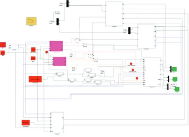
The dynamic milling force model is programmed in Matlab-Simulink and shown in Figure 7. It allows calculation of milling forces and tool displacements. Time history of tool displacements is used to assess the stability of machining.
Figure 7. Matlab-Simulink model for dynamic milling force model
Figures 8 (a) and (b) show milling force predictions
for slot milling of 45° unidirectional and multidirectional
CFRP laminates. Good agreements between prediction (Figure 8(a)) and measurement (Figure 4(b)) is obtained.
5.55 5.6 5.65 5.7 5.75 5.8 5.85 x 10⁴ -150 -100 -50 0 50 100 150 Time (s) M illi n g F o rc e s (F x, F y) (N ) Fx Fy (a)
0 500 1000 1500 2000 -150 -100 -50 0 50 100 150 Time Step M illi n g F o rc e s (F x, F y) (N ) (b)
Figure 8. (a) Predicted forces during slot milling of 45° fiber laminate, (b) Predicted forces for multidirectional laminate (at 3500 rpm, 0.02 mm/tooth, and 3 mm axial depth of cut)
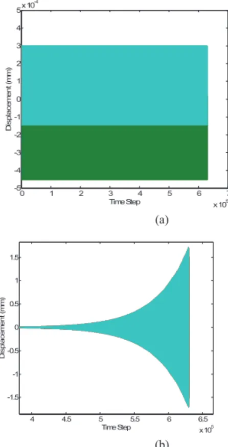
Figures 9(a) and (b) show the tool displacements where the axial depth of cut is taken as 10 and 16.8 mm, respectively. While machining is stable at 10 mm axial depth of cut, it becomes unstable at 16.8 mm of axial depth of cut for 3500 rpm rotational speed. It must be noted that the process damping effect is not included in the milling model. Process damping is known to further improve machining stability due to additional damping between tool flank face and the work material.
0 1 2 3 4 5 6 7 x 10⁵ -5 -4 -3 -2 -1 0 1 2 3 4 5x 10 -4 Time Step D is p la ce me n t ( mm) (a) 4 4.5 5 5.5 6 6.5 x 10⁵ -1.5 -1 -0.5 0 0.5 1 1.5 Time Step D isp la ce m e n t ( m m ) (b)
Figure 9. Time domain response of tool displacement. (a) Axial depth of cut 10 mm, (b) Axial depth of cut 16.8 mm.
7. Conclusions
A sine function is used to represent the average relationship between cutting force coefficients and fiber cutting angle. Sine function is shown to yield good force predictions during milling of CFRP laminates. Dynamic milling forces are calculated based on the laminate direction configuration and milling stability limit is calculated.
8. References
[1] Sheikh-Ahmad JY. Machining of Polymer Composites, Springer; 2009.
[2] Teti R. Machining of composite materials, CIRP Annals Manufacturing Tech. 2002; 51; 611-634.
[3] Koplev A. Cutting of CFRP with single edged tools. 3rd International Conference on Composite Materials, Paris, 1980. [4] Koplev A, Lystrup A, Vorm T. Cutting process, chips and cutting
forces in machining CFRP. Composites, 1983; 14(4); 371-376. [5] Hocheng H, Puw H, Huang Y. Preliminary study on milling of
unidirectional carbon-fibre reinforced plastics, Composites Manufacturing, 1993; 4(2); 103-108.
[6] Wang D, Ramulu M, Arola D. Orthogonal cutting mechanisms of graphite/epoxy composite. Part 1: Unidirectional laminate. Int. J. Mach. Tools and Mfg. 1995; 35(12); 1623-1638.
[7] Wang D, Ramulu M, Arola D, Orthogonal cutting mechanisms of graphite/epoxy composite. Part 2: Multidirectional laminate. Int. J. Mach. Tools and Mfg. 1995; 35(12); 1639-1648.
[8] Kalla D, Sheikh- Ahmad J, Twomey J. Prediction of cutting forces in helical end milling fiber reinforced polymers, Int. J. Mach. Tools and Mfg. 2010; 50; 882-891.
[9] Sahraie Jahromi A, Bahr B. An analytical method for predicting cutting forces in orthogonal machining of unidirectional composites, Composite Science and Technology, 2010, 70, 2290-2297.
[10] Hintze W, Hartmann D, Schütte C, Occurrence and propagation of delamination during the machining of carbon fibre reinforced plastics (CFRPs) – An experimental study, Composites Science and Technology, 2011; 71(15); 1719-1726.
[11] Lopez de Lacalle N, Lamikiz A, Campa FJ, Valdivielso FDZ, Exteberria I, Design and test of a multitooth tool for CFRP milling, Journal of Composite Materials, 2009; 43; 3275-3290. [12] Y. Altintas, Manufacturing automation, Cambridge University
Press, 2000.
[13] Faassen RPH, van de Wouw N, Oosterling JAJ, Nijmeijer H. Prediction of regenerative chatter by modelling and analysis of high-speed milling, Int. J. of Mach. Tools and Mfg. 43; 2003; 1437–1446.