INVITED PAPER
Pulse Shaping For A Long-Distance Optical
Synchronization System
F. ¨O. ILDAY†,††, A. WINTER†††, F. X. K ¨ARTNER††, and M.B. DANAILOV††††,
SUMMARY Next generation free electron lasers aim to gen-erate x-ray pulses with pulse durations down to 30 fs, and possi-bly even sub-fs. Synchronization of various stages of the acceler-ator and the probe laser system to the x-ray pulses with stability on the order of the pulse width is necessary to make maximal use of this capability. We are developing an optical timing synchro-nization system in order to meet this challenge. The scheme is based on generating a train of short optical pulses, with a pre-cise repetition frequency, from a mode-locked laser oscillator and distributed via length-stabilized optical fibers to points requiring synchronization. The timing information is embedded in the rep-etition frequency and its harmonics. A significant advantage of the optical synchronization system is that multiple mode-locked Ti:sapphire seed oscillators typically present in an accelerator fa-cility can be replaced by the master mode-locked fiber laser. In this paper, we briefly review progress on the development of the synchronization system and then discuss the implementation of this new possibility. Several technical issues related to this ap-proach are analyzed.
key words: accelerator, femtosecond synchronization systems, fiber laser, ultra-short pulse propagation
1. Introduction
One of the key challenges for the new, fourth-generation light sources such as the European XFEL, 4GLS and FERMI@ELETTRA is to implement a timing stabi-lization and distribution system that allows the full ex-ploitation of the potentially ∼ 10 fs x-ray pulse for time-resolved studies. To this end, an ultra-stable timing and synchronization system must be implemented, cov-ering the critical subsystems of the machine and the ex-perimental area, which are spread over distances rang-ing from several hundred meters to several kilometers. The electron beam needs to enter the undulator with timing jitter comparable to the pulse duration, which puts significant pressure on the synchronization system and requires point-to-point stabilization of various RF frequencies for the critical components (booster section, injector, bunch compressors and experimental area) with femtosecond precision. In case of the European XFEL, this translates to an amplitude and phase sta-bility of the accelerating radio-frequency in the critical
Manuscript received September 20, 2006. Manuscript revised October 6, 2006. †
Department of Physics and National Nanotechnology Research Center, Bilkent University, Turkey
††Department of Electrical Engineering, MIT, USA
†††Deutsches Elektronen-Synchrotron, Germany
††††
Sincrotrone-Trieste, 34012 Trieste, Italy
Master Laser Oscillator stabilized fibers fiber couplers RF-optical sync module RF-optical sync module RF-optical sync module low-level RF low-noise microwave oscillator low-bandwidth lock remote locations
Fig. 1 Schematic of the optical timing synchronization system.
cavities of 10−4 rms and 0.01 deg rms respectively [1].
Even though the amplitude stability requirement is ex-tremely tight, it seems feasible to achieve, looking at the present results achieved in present day facilities, e.g. at JLAB and FLASH at DESY [2], [3]. However, in order to accurately measure the phase stability, one requires a high-quality reference with much smaller phase jit-ter than the signal to be measured. A key challenge is to provide this reference in facilities spanning a few kilometers in length.
These requirements on the timing stability appear to be beyond the capability of traditional RF distri-bution systems based on temperature-stabilized coax-ial cables. A promising way to reach this goal is to use an optical transmission system, depicted schemati-cally in Figure 1 [4]. A train of sub-picosecond pulses of light generated from a mode-locked laser with very low timing jitter is distributed over actively length-stabilized optical fiber links to an arbitrary number of remote locations. The precise repetition frequency of the pulse train, as well as its upper harmonics, contain the synchronization information. At the remote loca-tions, low-level RF signals can be extracted simply by using a photodiode and a suitable bandpass filter to pick the desired harmonic of the laser repetition rate, or by phase locking an RF source to a harmonic of the pulse train [5]. Optics has two fundamental advantages over traditional RF technologies: (i) optical frequen-cies are in the 100 THz range, enabling femtosecond resolution, and (ii) photons are immune to electromag-netic interferences, easing noise-free transportation of the signals.
2. Mode-locked fiber lasers
advantages as optical master oscillators [6], because of the ease of coupling to the fiber distribution sys-tem, their excellent long-term stability, and the well-developed and mature component base available at the optical communications wavelength of 1550 nm. Re-cently, their technical capabilities have also improved significantly [7]. Fiber lasers can generate pulses from picosecond down to sub-100 fs in duration by simul-taneous phase coherent lasing of multiple longitudi-nal modes spaced in frequency by the pulse repetition rate of the laser. During photodetection, these optical modes beat in the photo detector and generate all har-monics of the repetition rate within the bandwidth of the photodetector.
Mode-locking is initiated by a mechanism provid-ing lower loss (hence, higher net gain) for a pulse than for continuous wave (cw) radiation, leading to pulse formation from intra-cavity noise soon after the laser reaches a certain intra-cavity average power. For pas-sively mode-locked lasers, this is achieved by a real or artificial saturable absorber. Once the pulses are short-ened, the laser dynamics are dominated by an interplay of group velocity dispersion (GVD) (different frequen-cies have different speeds) and Kerr nonlinearity (the refractive index depends on intensity), leading to the formation of soliton-like pulses, which intrinsically bal-ance dispersion and nonlinearity [8]. Since the gain process has a finite bandwidth, the generated pulses need to be stabilized by the saturable absorber, which favors the pulse and suppresses any cw-radiation. At the simplest level, short-pulse laser dynamics can be characterized by four basic processes: gain, saturable absorption, Kerr nonlinearity, and dispersion interact-ing in a repetitive way, defined by the optical cavity (Fig. 2). gain saturable absorber dispersion Kerr nonlinearity
Fig. 2 The four main effects governing pulse shaping in mode-locked fiber lasers.
It is essential that the laser serving as the master oscillator has extremely low timing jitter (phase noise), particularly at high frequencies (> 10 kHz), where fur-ther suppression through feedback is difficult. The rep-etition rate of the laser corresponds to the inverse of the length of its cavity divided by the group velocity of the pulse. For a free-running laser, the cavity length fluctuates, as a result of environmental factors, such as temperature variations and acoustic vibrations. This causes timing jitter of a small amount. The timing of the pulse circulating in the laser cavity is affected also
by the intrinsic noise sources such as pump noise and amplified spontaneous emission noise from the amplifi-cation process. Ultimately, timing jitter is limited by quantum fluctuations in the number of photons making up the pulse and the incoherent photons added in the cavity due to spontaneous emission. The phase noise is extremely low at high offset frequencies (i.e., over short measurement times), but grows toward small off-set frequencies (i.e., over longer measurement times). The remedy is to control the repetition rate of the laser oscillator with a microwave oscillator possessing lower phase noise at low frequencies through a feedback loop. The bandwidth of the latter should be chosen to be close to the frequency where the phase noise of the laser oscillator and the microwave oscillator meet (∼ 1 kHz). Overall, a superior oscillator is formed by this combi-nation: at high offset frequencies, the laser phase noise is excellent and at low offset frequencies, the laser es-sentially follows the microwave oscillator.
A stretched-pulse Er-doped fiber laser was con-structed [9]. The laser cavity setup is illustrated in Fig. 3. The Erbium-doped fiber, which has normal
GVD of 75 ps2/km, is about 1 m long. It is pumped
by a 980-nm diode with total power of approximately 350 mW. The Er-fiber is followed by about 2.6 m of
SMF-28 (β2 = −23 ps2/km) and a small amount of
Corning Flexcor 1060 (β2 = −7 ps2/km), which
func-tions as connector fibers of the couplers and the isola-tor. Total dispersion of the cavity is adjusted to be
∼ 0.01 ps2. The repetition rate is ∼ 40 MHz. A
polarization-insensitive isolator provides unidirectional operation. Mode-locking is initiated and stabilized by nonlinear polarization rotation [10]. The laser produces linearly chirped pulses of ∼ 1.5 ps duration, which can be compressed to ∼ 100 fs external to the laser cav-ity. The pump power is typically set such that the power from the free space port is about 20 mW, avoid-ing any multiple-pulsavoid-ing instabilities, although higher power levels with single pulse operation are possible. Operation of the mode-locked operation is character-ized by monitoring the optical spectrum, the RF spec-trum of the pulse train and nonlinear autocorrelation of the pulses.
isolator &
5% coupler free space portfor diagnosis
980 nm/1550 nm pump coupler 980-nm pump diode SMF-28 SMF-28 (260 cm) 5% fiber port Er-doped fiber (100 cm)
Fig. 3 Schematic of the laser cavity setup: SMF-28, Corning-made single-mode fiber.
harmonic at 1.3 GHz was extracted from the pulse train upon photodetection and filtering. The integrated tim-ing jitter from 1 kHz to the Nyquist bandwidth, i.e., half of the laser repetition rate, is measured to be about 10 fs (Fig. 4). For comparison, the phase noise of a low-noise frequency generator, a Marconi 2041, is also plotted. As the laser is free running during these mea-surements, the performance of the microwave oscillator is superior in the low frequency regime (< 10 kHz), but the laser has lower noise at higher frequencies.
The noise characteristics of mode-locked lasers is well-described using soliton-perturbation theory, along with quantum noise sources [11]. These perturbations cause fluctuations in amplitude, phase, timing and cen-ter frequency. The last of these further contributes to timing in the presence of dispersion, i.e. a shift in cen-ter frequency is translated into timing shift via disper-sion, which is known as the Gordon-Haus jitter [12]. For a mode-locked fiber laser with small net dispersion and otherwise typical parameters, the quantum-limit is extremely small, on the order of 1 fs (from 1 kHz to 20 MHz, for a repetition rate of 40 MHz). How-ever, the measured timing jitter is substantially higher than the noise limit given by the spontaneous emission noise. Several effects in the photodetection process lead to significant distortion of the actual phase noise spec-trum. Due to the filtering of a single harmonic of the laser repetition rate, the power level of this harmonic is on the order of -20 dBm, even when saturating a typ-ical photodetector. The thermal noise floor of the 50 Ohm resistor used to terminate the photodiode is at 178 dBm. That results in a minimum noise floor of -158 dBc for the single sideband phase noise. The phase noise measurement device employed in this study (Agi-lent 5052A) implements a correlation technique, which provides an additional noise suppression of up to 20 dB of its internal phase reference used in measuring the laser phase noise. Even with this improvement, the phase noise of the reference oscillator itself limits the measurement in certain frequency bands. Another ef-fect, which may plague phase noise measurements, is amplitude to phase conversion in the photodiode [13].
3. Measurement of the Synchronization
Sys-tem in an Accelerator Environment
A test version of the optical synchronization system was constructed in the laboratory and its sub-components have been tested. However, owing to the presence of significant electromagnetic interference, acoustic noise and relatively poor temperature and vibrational isola-tion, operation in an accelerator environment can be expected to be more difficult than a university labora-tory. Therefore, to test this system under more real-istic conditions, measurements were conducted at the MIT-Bates Linear Accelerator Center. We utilized a 500 m-long single-mode optical fiber link, which was
103 104 105 106 107 108 -180 -160 -140 -120 -100 -80
Fig. 4 Single-sideband phase noise spectral density for the fiber laser and a Marconi 2041 signal generator.
already installed to achieve picosecond-stability optical signal transmission. The experiment consisted of three separate parts:
(i) Locking of the EDFL to the S-band master oscilla-tor at the Bates Facility to reduce the close-in noise of the laser system,
(ii) Stabilizing the fiber link with a RF-based feedback to reduce the timing jitter added by the transmission to a few femtoseconds,
(iii) Recovering a returning RF signal after 1 km of to-tal travel through the fiber link with minimal added jitter. The experiment was conducted over a time span of 3 weeks. The fiber laser worked reliably during this time without loss of mode-locking or significant increase of its phase noise. The details of these results will be reported elsewhere [14].
4. Integrated Pulse Shaping and Amplification
for Seeding Amplifiers
The next-generation light sources will be utilizing mul-tiple mode-locked lasers, scattered over the facility and fulfilling various different functions. These lasers in-clude photoinjector laser, laser heater, lasers for pump-probe experiments in the end-stations. At the present time, many of these lasers are amplified Ti:sapphire lasers, operating at or around 780 nm. All of these lasers must also be synchronized to the overall sys-tem and continue to operate uninterrupted for extended periods of time. A natural extension of the optical synchronization system is to utilize the same pulses to directly seed Ti:sapphire amplifiers, following ap-propriate pulse shaping, amplification and
frequency-doubling to 780 nm. Furthermore, the laser heater
and additional diagnostic lasers can be implemented at the Er-fiber wavelengths, without resort to frequency-doubling. Thus, the optical synchronization scheme along with direct seeding offers the possibility of replac-ing multiple Ti:sapphire lasers oscillators with a sreplac-ingle fiber laser.
A unified synchronization-seeding architecture of-fers significant simplification and cost-reduction. The most valuable benefit might be in terms of system up-time. Mode-locked lasers cannot offer completely reli-able operation. Fiber lasers have excellent long-term stability. Furthermore, if fewer (perhaps a single) laser oscillator will be running, any downtime due to laser failure will be greatly reduced: Fiber lasers have low enough costs that it is reasonable to install multiple lasers for the same task, offering the benefit of redun-dancy. If the laser in actual use fails, the system can rapidly (through optical modulators acting as gates) switch to another fiber laser possibly without human intervention. Another advantage is that direct seeding from a single laser oscillator eliminates the inevitable residual timing jitter from the synchronization of two lasers. The arguments outlined above assume that (i) pulses with desirable parameters (stability, duration and energy) can be provided at 780 nm, and (ii) during the propagation, amplification and reshaping no signif-icant jitter is added. In this section, guided by numer-ical simulations, we analyze the technnumer-ical feasibility of delivering the desired parameters.
Pulse propagation in the optical fiber link is de-scribed with a nonlinear Schr¨odinger equation (NLSE), extended to include higher-order dispersion and the Ra-man effect. Around 1550 nm, fibers of either sign of dispersion (normal and anomalous) are commercially available, permitting the construction of fiber links with nearly zero dispersion by choosing two fibers of
op-posite dispersion. Regular single-mode fiber (SMF)
has anomalous second-order dispersion of −23 ps2/km.
Fiber with normal dispersion is commonly referred to as dispersion-compensating fiber (DCF). If two fiber segments of either sign are used, the GVD of a link can always be set to zero by choosing the correct ratio of the two fiber lengths. Ideally, the dispersion slopes of the fibers must also match in magnitude and be opposite in sign (removing higher-order dispersion contributions).
Depending on the facility, there may be distinct regimes of interest, pulses as short as possible and longer, ps pulses, corresponding to the short-pulse and the long-pulse operation modes of the accelerator. The two regimes offer different challenges to the direct seed-ing scheme. In this study, the short-pulse regime tar-gets 120 fs-long pulses. For these pulses, higher-order dispersion (at least the leading term, third-order dis-persion (TOD)) is significant and residual disdis-persion of the fiber link and the pulse shaping modules must be carefully minimized. For longer pulses, which we take as 1 ps-long in this study, higher-order dispersion is no longer a serious problem. However, the challenge arises from the need to amplify the pulse energy, since chirped-pulse amplification [15] is difficult to implement for long pulses.
DCFs have been commercially developed for the telecommunications industry and can match the
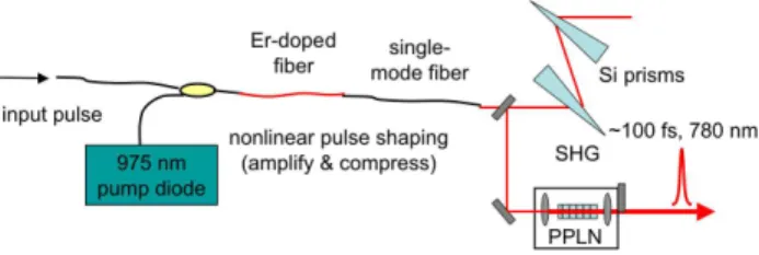
disper-Fig. 5 Schematic of direct seeding of Ti:sapphire amplifiers by amplified, shaped, and frequency-doubled pulses derived directly from the optical synchronization system.
sion profile of regular fiber with great precision over the 1500-1600 nm window. However, the high levels of ra-diation to be present in the accelerator tunnel prohibit the use of regular fiber. Radiation hardened fiber (up to 3000 rad, sufficiently resistant for operation for sev-eral years) is commercially available with parameters essentially identical to the standard Corning SMF-28 fiber [16]. Thus, radiation-hardened SMF can form the fiber links in the tunnel and a DCF spool at either end point of the link can be utilized in a radiation-shielded area. Since the dispersion/length is higher (as much as 5-10 times) for DCF than SMF-28, the overall length of the link is increased by about 10−20%. With presently available DCF, the slope of dispersion (TOD) can be matched to within a few percent, while setting the dis-persion of the central wavelength to zero. We estimate the effective (treating the whole link as a single fiber)
characteristic length for TOD, LTOD= 140 m for a 5%
mismatch. TOD is weak if LTOD ≥Llink, where Llink
is the total length of the link. Although techniques for careful matching can reduce TOD much further [17], these approaches are difficult to implement.
In order to minimize self-phase modulation due to nonlinear effects occurring in the fiber link, the pulse energy needs to be kept low, around 100 pJ. There-fore, the pulses must be amplified at the end of the link. This introduces a limitation to bandwidth due to pulse broadening (gain narrowing). For 100 fs pulse duration and amplification to 5-8 nJ of pulse energy, the effect was observed to be minor in a Yb-fiber am-plifier, with 120 fs pulses achieved, limited partially by residual third-order dispersion [18]. Another limitation to pulse bandwidth arises from frequency-doubling of the pulses to 780 nm. The finite phase-matching band-width renders it difficult to achieve pulse durations less than 110 fs. It may be possible to increase the band-width with special PPLN structures [19]. High con-version efficiencies (30%) can be achieved in a periodi-cally poled Lithium Niobate (PPLN) crystal [20]. For the case of broadband (100 fs) pulses, a particularly interesting idea is to simultaneously compress and fre-quency double the pulses in a chirped-period PPLN structure [21].
The fiber amplifier needs to be designed to min-imize degradation of pulse quality and added noise.
−500 0 500 0 0.2 0.4 0.6 0.8 1
Power (arb. un.)
Time Delay (fs) 1500 1550 1600 0 0.2 0.4 0.6 0.8 1
Power (arb. un.)
Wavelength (nm) −500 0 500 0 0.2 0.4 0.6 0.8 1
Power (arb. un.)
Time Delay (fs)
(a) (b) (c)
Fig. 6 Results of numerical simulations for the short pulse regime: (a) pulse shape at 1560 nm after compression, (b) cor-responding optical power spectrum, and (c) pulse shape at 780 nm, assuming perfect phase-matching.
In SMF-28, the fundamental soliton energy for 100 fs pulses is slightly less than 1 nJ. On the other hand, in order to provide ample amount of seed energy, we tar-get 3 nJ as the energy of the pulses out of the fiber, such that 1 nJ can be obtained in the second-harmonic. This is higher than the fundamental soliton energy; clearly these energy levels cannot be attained in regular SMF without severe nonlinear distortions. A way to over-come this limitation is to amplify stretched pulses and then compress them to the desired duration in an exter-nal compressor, as illustrated in Fig. 5. The difficulty is more acute in the long pulse (1 ps) regime, because the narrower spectrum makes it difficult to stretch the pulse via dispersion. Amplification in fiber with normal dispersion minimizes the adverse effects of Kerr nonlin-earity [22]. The fiber link can be configured to supply positively chirped pulses (by slightly overcompensating the dispersion of the radiation-hardened fiber). Nev-ertheless, normal-dispersion Er-fiber requires tighter mode confinement, since the dispersion shift is due to strong waveguide dispersion. Under these conditions, the launched pulse should be chirped to at least several ps to take the nonlinear effects under control. Following amplification, compression to near-transform limit is achieved with a compressor comprised of Brewster-cut Si prisms. The high dispersion of Si (∼ 1000 fs2/mm)
permits a manageable prism to prism spacing of less than 1 m [23]. An alternative approach is to use large-mode area fibers, including single-large-mode operation of nominally multi-mode fibers [24], but this approach in-troduces other technical problems arising from imper-fect suppression of the higher-order modes. The ghost pulses created by the higher-order modes can be detri-mental for phase noise measurements.
Numerical simulations are used to test these ex-pectations. An extended NLSE with TOD and the Raman-induced nonlinearity is solved numerically for a Gaussian launched pulse of 90 pJ energy and full-width at half-maximum (FWHM) of 100 fs. The length of the radiation hardened section of the fiber link is taken to be 200 m, which would be adequate, for ex-ample, for the FERMI accelerator. Dispersion at 1560 nm is slightly overcompensated to pre-chirp the pulses
−2000 0 2000 0 0.2 0.4 0.6 0.8 1
Intensity (A. U.)
Time Delay (fs) 1550 1560 1570 0 0.2 0.4 0.6 0.8 1
Intensity (A. U.)
Wavelength (nm) −2000 0 2000 0 0.2 0.4 0.6 0.8 1
Intensity (A. U.)
Time Delay (fs)
(a) (b) (c)
Fig. 7 Results of numerical simulations in long pulse regime: (a) pulse shape at 1560 nm after compression, (b) corresponding optical power spectrum, and (c) pulse shape at 780 nm, assuming perfect phase-matching.
to 350 fs before entering the Er-fiber amplifier. We assume a dispersion slope mismatch of 5%. Following the dispersion-managed fiber link, the pulses are am-plified in a 100 cm-long Er-fiber with small signal gain of 30 dB, dispersion coefficient of 75 ps2/km and an
effective area of 30 µm2. The energy after
amplifica-tion is 3.1 nJ and the pulses are broadened to 2.25 ps. Compression is done in SMF-28, followed by free-space Si-prism compressor for the last stage to avoid nonlin-ear distortions. Thus, the compressor is assumed to be ideal, i.e., linear and without higher-order disper-sion. The pulse energy is further reduced to 2.95 nJ by the compressor (Si prism compressor routinely provide 95% transmittance). Compression reduces the pulse width to 138 fs, limited by residual TOD (Fig. 6a). The spectral shape is nearly parabolic (Fig. 6b), due to the nearly self-similar evolution of the pulse during amplification [25]. Frequency-doubling to 780 nm fur-ther reduces the pulse duration to 95 fs, where we have assumed perfect phase-matching over the entire band-width of the pulse for simplicity (Fig. 6c). This is quite difficult to ensure in practice and 120 fs is a more real-istic target.
For the case of 1 ps pulses, we start with even longer pulses, 1.7 ps of duration. In this case, TOD is negligible. Adopting an Er-fiber with parameters
similar to SMF-28 (−23 fs2/mm, effective area of ∼
80 µm2) and 200 cm in length, permits amplification
to 3.4 nJ without significant nonlinear distortion. Due to the extra bandwidth generated during amplification, the compressed pulse duration is 1.08 ps at 1560 nm and 670 fs at 780 nm, assuming perfect phase-matching (Fig. 4).
Seeding solid-state amplifiers with frequency-doubled Er-fiber lasers is a proven concept in the ab-sence of the extremely stringent requirements on noise level that the accelerator applications demand. This approach forms the basis of commercial regenerative amplifier products. However, it is clear from these nu-merical simulations that attaining the goals for pulse shaping and delivery require several technical chal-lenges to be met. Finding the right combination of fiber and pulse parameters can be difficult and
exten-sive numerical/experimental investigations are neces-sary to carefully explore the limits and the tolerances on the parameters, as set by fiber nonlinearities and to determine the effects of pulse shaping and amplification on the timing jitter for the accelerator implementation. Initial results indicate that added amplitude and phase noise can be minimized with proper design of the fiber amplifier, namely by avoiding excessive nonlinearities as well as preventing ASE breakthrough [26].
5. Conclusion and Outlook
In conclusion, mode-locked fiber lasers producing sub-ps pulses can serve as ultra-low noise master oscillators for timing distribution in next-generation light sources. The main advantage of mode-locked fiber laser is the ex-cellent noise performance at high frequencies, the high quality and availability of pump sources and compo-nents in the 1550 nm wavelength range. Measurements show a high-frequency performance surpassing that of microwave oscillators with ultra-low phase noise. We have demonstrated sources with ultra-low timing jit-ter of 10 fs in a bandwidth of 1 kHz to the Nyquist frequency. Such sources can be made readily available for sub-100 fs and potentially sub-50 fs timing distri-bution. A particularly advantageous possibility offered by the optical synchronization system is to shape and amplify these pulses such that they can be used to seed Ti:sapphire laser amplifiers typically present in these facilities. Preliminary numerical studies indicate that this approach is feasible. Several technical challenges, which need to be overcome, have been addressed.
6. Acknowledgments
The authors acknowledge support by the staff of the
MIT-Bates Laboratory. The experimental
measure-ments were carried out at MIT. One of the authors
(F ¨OI) acknowledges support by T ¨UBA-GEBIP and
T ¨UBITAK Grant No. 106T017.
References
[1] H. Schlarb et. al., “Next generation synchronization system for the VUV-FEL at DESY,” FEL Conference 2004, Trieste, Italy, 2004.
[2] M. Liepe, “Superconducting RF and RF Control” Proceed-ings of the ERL 2005 Workshop,” Jefferson Lab, Newport News, VA.
[3] S. Simrock, “Overview of options for RF control & state of the art, simulation results and performance test results” Proceedings of the ERL 2005 workshop, Jefferson Lab, Newport News, VA.
[4] J. W. Kim et. al., “Large scale timing distribution and RF-synchronization for FEL facilities,” FEL Conference 2004, Trieste, Italy, 2004.
[5] J. Kim, F. X. K¨artner, and M. H. Perrott, “Femtosecond synchronization of radio frequency signals with optical pulse trains,” Opt. Lett. 29, 2076-2078 (2004).
[6] A. Winter et. al., “Towards high-performance optical mas-ter oscillators for energy recovery linacs,” Nucl. Inst. Meth. A 557, 299-304 (2006).
[7] F. ¨O. Ilday, J. R. Buckley, H. Lim, and F. W. Wise, “Gener-ation of 50-fs, 5-nJ pulses at 1.03 µm from a wave-breaking-free fiber laser,” Opt. Lett. 28, 1365-1367 (2003).
[8] H. A. Haus, “Mode-locking of lasers,” IEEE J. Sel. Top. Quantum Electron. 6, 1173-1185 (2000).
[9] K. Tamura, E. P. Ippen, H. A. Haus, and L. E. Nelson, “77-fs pulse generation from a stretched-pulse mode-locked all-fiber ring laser,” Opt. Lett. 18, 1080-1082 (1993). [10] M. Hofer, M. E. Fermann, F. Haberl, M. H. Ober, and A.
J. Schmidt, Opt. Lett. 16, 502 (1991).
[11] S. Namiki, and H. A. Haus, “Noise of the stretched pulse fiber ring laser: part I - theory,” IEEE J. Quantum Elec-tron. 33, 649-659 (1997).
[12] J. P. Gordon, and H. A. Haus, “Random walk of coherently amplified solitons in optical fiber transmission,” Opt. Lett. 11, 665-667 (1986).
[13] E. N. Ivanov, S. A. Diddams and L. Hollberg, “Analysis of noise mechanisms limiting the frequency stability of mi-crowave signals generated with a femtosecond laser,” IEEE J. Sel. Top. Quantum Electron. 9, 1059-1065 (2003). [14] F. ¨O. Ilday, A. Winter, and F. X. K¨artner, manuscript in
preparation.
[15] D. Strickland and G. Mourou, “Compression of amplified chirped optical pulses,” Opt. Commun. 56, 219-221 (1985). [16] See, for example, J-fiber GmbH, radiation-hardened
single-mode fiber data sheet.
[17] S. Shen, A. M. Weiner, “Complete dispersion compensation for 400-fs pulse transmission over 10-km fiber link using dis-persion compensating fiber and spectral phase equalizer,” IEEE Photon. Tech. Lett. 11, 827-829 (1999).
[18] F. ¨O. Ilday, H. Lim, J. R. Buckley, and F. W. Wise, “Practi-cal all-fiber source of high-power, 120-fs pulses at 1 micron,” Opt. Lett. 28, 1362-1364 (2003).
[19] N. E. Yu, S. Kurimura, K. Kitamura, J. H. Ro, and M. Cha, “Efficient frequency doubling of a femtosecond pulse with simultaneous group-velocity matching and quasi phase matching in periodically poled, MgO-doped lithium nio-bate,” Appl. Phys. Lett. 82, 3388-3390 (2003).
[20] M. A. Arbore, M. M. Fejer, M. E. Fermann, A. Hariharan, A. Galvanauskas, and D. Harter, “Frequency doubling of femtosecond erbium-fiber soliton lasers in periodically poled lithium niobate,” Opt. Lett. 22, 13-15 (1997).
[21] M. A. Arbore, A. Galvanauskas, D. Harter, M. H. Chou, and M. M. Fejer, “Engineerable compression of ultrashort pulses by use of second-harmonic generation in chirped-period-poled lithium niobate,” Opt. Lett. 22, 1341-1343 (1997).
[22] K. Tamura and M. Nakazawa, “Pulse compression by non-linear pulse evolution with reduced optical wave breaking in erbium-doped fiber amplifiers,” Opt. Lett. 21, 68-70 (1996). [23] G. Lenz, K. Tamura, H. A. Haus, and E. P. Ippen, “All-solid-state femtosecond sources at 1.55 mu-m,” Opt. Lett. 20, 1289-1291 (1995).
[24] M. E. Fermann, A. Galvanauskas, M. Hofer, “Ultrafast pulse sources based on multi-mode optical fibers,” Appl. Phys. B 70, S13-S23 (2000).
[25] V. I. Kruglov, A. C. Peacock, J. M. Dudley, and J. D. Harvey, “Self-similar propagation of high-power parabolic pulses in optical fiber amplifiers,” Opt. Lett. 25, 1753-1755 (2000).
[26] F. ¨O. Ilday, J. Chen, A. Winter, F. W. Wise, O. Skhurikhin, and D. Gapontsev, “Low-noise, high-energy, single-mode, femtosecond fiber laser system,” Proceedings of the Con-ference on Lasers and Electro-Optics, 825-827 (2005).