KADIR HAS UNIVERSITY
GRADUATE SHOOL OF SCIENCE AND ENGINEERING
OPTIMAL RATE AND POWER ALLOCATION ALGORITHM IN
TDD-OFDM BASED TWO-TIER FEMTOCELL NETWORKS
Graduate Thesis
MHD TAHSSIN ALTABBAA
Mhd Ta hssi n AL TA B B AA M.S . The sis 20 15 S tudent’ s F ull Na me P h.D. (or M.S . or M.A .) The sis 20 11
-
OPTIMAL RATE AND POWER ALLOCATION ALGORITHM IN
TDD-OFDM BASED TWO-TIER FEMTOCELL NETWORKS
MHD TAHSSIN ALTABBAA
Submitted to the Graduate School of Science and Engineering in partial fulfillment of the requirements for the degree of
Master of Science in
Electronics Engineering
KADIR HAS UNIVERSITY January 2015
KADIR HAS UNIVERSITY
GRADUATE SCHOOL OF SCIENCE AND ENGINEERING
OPTIMAL RATE AND POWER ALLOCATION ALGORITHM IN
TDD-OFDM BASED TWO-TIER FEMTOCELL NETWORKS
MHD TAHSSIN ALTABBAA
APPROVED BY:
Prof. Erdal Panayırcı (Kadir Has University) (Thesis Supervisor)
Prof. Hakan Ali Çırpan (Istanbul Technical University)
Asst. Prof. Taner Arsan (Kadir Has University)
APPROVAL DATE: 10/01/2015 AP PE ND IX C APPENDIX B APPENDIX B
“I, MHD TAHSSIN ALTABBAA, confirm that the work presented in this thesis is my own. Where information has been derived from other sources, I confirm that this has been indicated in the thesis.
i
Abstract
OPTIMAL RATE AND POWER ALLOCATION ALGORITHM IN
TDD-OFDM BASED TWO-TIER FEMTOCELL NETWORKS
MHD TAHSSIN ALTABBAA
Master of Science in Electronics Engineering
Advisor: Prof. Dr. Erdal Panayırcı
Jan, 2015
People nowadays are witnessing the acceleration of development of electronics. The new technologies of electronic devices has made mobile phones smarter and more technologically advanced, where they support software platforms and applications that increased the demands on high data rates and gives the users the ability to play online games, video chat, upload-download data, and watch videos on social networks and other video-streaming websites. According to statistics of researches and telecommunication companies, the average usage area of a mobile data transfer users are generated from indoor places e.g. houses.
Mobile operators seeks out for providing high data rates to increase their capacity to suit the demands of indoor users for those who experience weak signal power; However, the current studies suggests a distance decreasing between the Mobile Station (MS) and Base Station (BS) for a lower distance of wireless communication. Femtocell technology, also called Home Base Station (HBS), provides a high data transfer rates and better coverage area for limited number of indoor users, where the conventional base station used by the telecommunication company that has a wide coverage correspondingly named Macro Base Station (MBS). In home base station technology, the femtocell users uses the same spectrum for uplink and downlink frequencies that the other mobile stations are using for communication with the MBS. AP PE ND IX C
ii
However, for such a communication system, it brings out a new area for research regarding interference management.
In this thesis, an adaptive power control algorithm based on the network’s present parameters with two constraints performed at the femtocell users’ uplink channels for interference mitigation in a Time Division Duplex-Orthogonal Frequency Division Multiplexing (TDD-OFDM) wireless communication fashion. The constraints aims to ensure the quality of service of communication of MBS’s user and to preserve the data rate of femtocell users from collapsing. The first constraint is regarding the mitigation of the interference coming from the femtocell user to the macro mobile station; this constraint depends on the availability of the time slot that both femtocell and macrocell users are sharing subject to a certain frequency. The second constraint is regarding the limitation of the femtocell user’s transmitting power based on the maximization of the weighted rate sum of the femtocell users subject to the power summation of each femtocell user on each subchannel.
Accordingly, we study the scenarios that considers both the cross-tier and co-tier interferences to mimic the realistic femtocell environment.
iii
Acknowledgements
I dedicate this work to my parents for their sincerity, devotion, tenderness, and caring; and I would like to show appreciation to my brother Khaldoun ALTABBAA for his substantial realistic and logistic support along the years.
Over the past two years, I have gained experience during my master studies from my professors at Kadir Has University through working on my dissertation with my supervisor Prof. Dr. Erdal PANAYIRCI, and being a student at Prof. Dr. Şirin TEKİNAY’s classes. In addition, I would like to thank Prof. Dr. Hakan ÇIRPAN, and Asst. Prof. Serhat ERKÜÇÜK for their distinguished provision, support, and understanding throughout their courses that I have attended. AP PE ND IX C APPENDIX B APPENDIX B
iv
Table of Contents
Abstract i Acknowledgements iii Table of Contents iv List of Figures vList of Symbols and Abbreviations vi
1. Introduction 1 2. Mobile Communications 5 2.1. Introduction ... 5 2.1.1. Location Management ... 6 2.1.2. Roaming ... 7 2.1.3. Handover ... 7 2.2. GSM System ... 8 2.2.1. GSM Network Architecture ... 9 2.3. UMTS System ... 11 2.3.1. WCDMA ... 12
2.3.2. UMTS Network Architecture ... 13
2.4. LTE and LTE-A Systems ... 15
2.4.1. Coordinated Multipoint ... 16
2.4.2. Carrier Aggregation ... 17
2.4.3. Frequency Division Multiplexing ... 18
2.4.4. LTE Network Architecture ... 19
3. Home Base Stations: Femtocells / Five Bar Coverage 22
3.1. Femtocell Technology ... 22
3.2. HNB and HeNB Network Architectures ... 23
3.3. Power Control in Femtocell Networks ... 27
3.3.1. System Model ... 27
3.3.2. Problem Formulation... 28
3.3.3. Optimal Distribution Subchannel, Rate and Power Allocation Algorithm ... 30
4. Computer Simulations and Main Results 35
5. Conclusions 40 References 42 AP PE ND IX C
v
List of Figures
Figure 2.1 GSM Network Architecture ... 11
Figure 2.2 Spread Spectrum, Spreading and Despreading ... 12
Figure 2.3 Bandwidth Allocation of WCDMA ... 13
Figure 2.4 UMTS Network Architecture ... 14
Figure 2.5 Components of UMTS Network ... 15
Figure 2.6 Downlink CoMP Transmission ... 17
Figure 2.7 Carrier Aggregation Scenarios ... 18
Figure 2.8 OFDM vs OFDMA Subcarrier Allocation ... 19
Figure 2.9 LTE Network Architecture ... 20
Figure 3.1 HeNB Network Architecture ... 24
Figure 3.2 HNB Network Architecture ... 26
Figure 3.3 System Model ... 28
Figure 3.4 System’s Occupied and Unoccupied Subchannels ... 29
Figure 4.1 Power Update Algorithm ... 36
Figure 4.2 Data Rate Convergence Process of Each Mobile Station for K = 4 ... 36
Figure 4.3 WRS as a Function of the Maximal Transmit Power for K = 4 ... 37
Figure 4.4 WRS as a Function of Outdoor Path Loss Component for K = 4 ... 37
Figure 4.5 WRS as a Function of Interference Tolerance Threshold for K = 4 ... 38
Figure 4.6 Data Rate Convergence for K = [50, 100] ... 38
Figure 4.7 Distribution of FMSs, MMS and MBS for K = [50, 100] ... 39
AP PE ND IX C APPENDIX B
vi
List of Abbreviations and Symbols
1G 1st Generation
2G 2nd Generation
3G 3rd Generation
3GPP 3rd Generation Partnership Project 3GPP2 3rd Generation Partnership Project 2 4G 4th Generation
AAA Authorization, Authentication and Accounting AMPS Advanced Mobile Phone System
AuC Authentication Centre
AWGN Additive White Gaussian Noise
BS Base Station
BSC Base Station Controller BSS Base Station Subsystem BTS Base Transceiver Station
CA Carrier Aggregation
CC Carrier Components
CDMA Code Division Multiple Access
CIBER Cellular Intercarrier Billing Exchange Record
CN Core Network
CoMP Co-ordinated Multipoint Transmission CS-MGW Circuit Switched Media Gateway
DS Doppler Shift
DSL Digital Subscriber Line
EC Echo Canceller
EDGE Enhanced Data rates for GSM Evolution EIR Equipment Identity Register
eNodeB/eNB E-UTRAN Node B
EP Element Procedure
EPC Evolved Packet Core
vii
EPS Evolved Packet System
E-TACS European-Total Access communication System ETSI European Telecommunications Standards Institute
E-UTRAN Evolved UTRAN
FAP Femtocell Access Point FBS Femtocell Base Station
FC Femtocell
FDD Frequency Division Duplex
FDMA Frequency Division Multiple Access
FFL Femto Forum Limited
FFT Fast Fourier Transform FFR Fractional Frequency Reuse
FGW Femtocell Gate Way
FMS Femtocell Mobile Station
GGSN Gateway GPRS Support Node
GMSC Gateway MSC
GMSK Gaussian Minimum Shift Keying GPRS General Packet Radio Service
GSM Global System for Mobile Communications
HeNB Home evolved Node B
HeNBMS HeNB Management System
HeNB-GW HeNB Gateway
HBS Home Base Station
HeNB PF HeNB Policy Function
HeNB-GW HeNB-Gateway
HLR Home Location Register
HNB Home Node B
HNBAP HNB Application Part
HNS HNB Subsystem
HNB-GW HNB Gateway
HSCSD High Speed Circuit Switched Data HSDPA High Rate Downlink Packet Access HSUPA High Rate Uplink Packet Access
viii HSS Home Subscriber Server
HSUPA High Rate Uplink Packet Access
IEEE Institute of Electrical and Electronics Engineers IMEI International Mobile Equipment Identity
IMSI International Mobile Subscriber Identity IMT International Mobile Telecommunications
IP Internet Protocol
ITU International Telecommunication Union IWF Internetworking Function
LA Location Area
LTDDF Listening-Time Division Duplex Frame
LTE Long Term Evolution
LTE-A Long Term Evolution-Advanced MBS Macrocell Base Station
MIMO Multiple-Input Multiple-Output
MME Mobility Management Entity
MMS Macrocell Mobile Station
MS Mobile Station
MSC Mobile Switching Centre
MSISDN Mobile Subscriber Integrated Services Digital Network Number MSRN Mobile Subscriber Roaming Number
NMT Nordic Mobile Telephone
NSS Network Switching Subsystem
OFDM Orthogonal Frequency Division Multiplexing OFDMA Orthogonal Frequency Division Multiple Access OMC Operation and Management Centre
PDN-GW Packet Data Network Gateway PAPR Peak to Average Power Ratio PDP Packet Data Protocol
PLMN Public Land Mobile Network
PSK Phase Shift Keying
PSTN Public Switched Telephone Network QAM Quadrature Amplitude Modulation QoS Quality of Service
APPENDIX B AP PE ND IX C AP PE ND IX C APPENDIX B
ix
QPSK Quadrature PSK
RF Radio Frequency
RAB Radio Access Bearer
RAN Radio Access Network
RANA Radio Access Network Relocation RANAP RAN Application Part
RNC Radio Network Controller
RNS Radio Network Subsystem
RRC Radio Resource Control
RUA RANAP User Adaptation
S1-AP S1-Access Part
SCTP Stream Control Transmission Protocol
SC-FDMA Single Carrier Frequency Division Multiple Access
SGSN Serving GPRS Support Node
SGW Serving Gateway
SIM Subscriber Identity Module
SINR Signal to Interference plus Noise Ratio SIR Signal to Interference Ratio
SMS Short Messaging Service SNR Signal to Noise Ratio
SS Spread Spectrum
TAP Transferred Account procedure
TDD Time Division Duplex
TDMA Time Division Multiple Access TH-CDMA Time Hopped CDMA
TDD-OFDM Time Division Duplex-Orthogonal Frequency Division Multiplexing
TNL SCTP Transfer Network Layer Stream Control Transmission Protocol
UE User Equipment
UMTS Universal Mobile Telecommunications System UTRAN UMTS Terrestrial Radio Access Network VLR Visitor Location Register
VoIP Voice over IP
x
WCDMA Wideband Code Division Multiple Access
WiMAX Worldwide Interoperability for Microwave Access
Rc MBS Coverage Area Radius
E Channel Gain
𝑃𝑘𝑚 Transmitting Power of FMS k on m
𝑃𝑖𝑚 Power of Femtocell User 𝑖 on m
𝑃𝑘𝑀𝐴𝑋 Maximum Transmitting Power allowed
𝑃𝑘∗𝑚 Equilibrium Power Equation of FMS k 𝑁𝑘𝑚 Noise Power of FMS k on m
𝑄𝑘𝑚 Interference at the Receiver of FMS k caused by MMS on m
M Number of Subchannels
m Subchannel
𝐼𝑚 Interference Tolerance
𝑓𝑚 Subchannel m Availability
ℎ𝑘𝑘𝑚 Channel Response between FMS k and its FBS on subchannel m
ℎ𝑘𝑖𝑚 Channel Response of FMS 𝑖 at FMS k on subchannel m
ℎ𝑘𝑚 Channel Response between FMS k and MMS on subchannel m
𝑤𝑘, 𝑤𝑖 Weight
𝑅𝑘 Rate of FMS k
𝜆𝑘 Shadow Price of FMS k’s Power
𝜇𝑚 Shadow Price of Subchannel m
𝛼1 Outdoor Path Loss Exponent
1
1. INTRODUCTION
In 1946, when Bell labs invented the very first mobile phone, the idea behind it was to serve the truck derivers’ fleets where they drive across the country (USA), and in need for a mobile communication to call their base station in case of accidents. At that time, the primitive network could not handle a large volume of calls; a single transmitter on a central tower with a handful of channels was enough to provide a wireless communication for an entire metropolitan area, where at most three truck drivers could make calls at a certain time in a certain city.
Along the years, communication methods has been increasingly developed with respect to technology changing and needs; for example, smart phones became smaller and cheaper, and as a result of this evolution, the number of subscribers incredibly increased, and the existent systems couldn’t handle the huge amount of subscribers.
However, mobile telecommunication companies and researchers had to find a newer generation based on a newer communication technique to enlarge the capacity of the system; otherwise, the system’s quality of service will fall. The conventional cellular concept was introduced by AT&T Bell Laboratories, where they invented the known GSM (Global System for Mobile Communications) using the famous technology of Frequency Reuse (FR), and achieved the mobility issues regarding users’ movement from a cell to another in case of an ongoing call (handover). Mobile operators designs their network to suit both coverage and capacity. Coverage enlargement not just offers a less location update mechanism and paging, but also a fewer capacity, which the latter leads to a low quality of service. On the other hand, if the operator uses Microcells and Picocells, this will reduce the coverage area, and gives a better capacity; but unfortunately, this solution has a high cost. For this reason, mobile operators’ researchers and scientists are working on a short-ranged low powered cellular structure to expand the coverage, capacity, and data rate for a better quality of service; this category of cellular structure were given the name (five bar coverage) [8], but the name femtocell, which is also known as home base stations [3] is more common. The researchers are working on a numerous of mechanisms to advance the home base station structure and meets the development of Long Term Evolution (LTE) and Long Term Evolution-Advanced (LTE-A) technologies with
2
respect to the famous communication techniques e.g. CDMA and OFDMA systems. Different aspects regarding the technical challenges for femtocell design are discussed through research papers, master and doctoral theses such as spectrum allocation, timing and synchronization, adaptation of femtocells on an existent network, quality of service requirements, interference managements, access methods, handoff and emergency services. In addition, recognized foundations like Femto Forum Limited (FFL), European Telecommunications Standards Institute (ETSI) and Third Generation Partnership Project (3GPP) are working on standardization of femtocells. Femto Base Station (FBS) design includes many ways for outer-communication; the latter can be connected to a backhaul with broadband connection such as; cable modem, Digital Subscriber Line (DSL) or with Radio Frequency channels [11]. As the demand on developing femtocell technology, there exists more than one communication topology for such a system. Researchers have been developing FBSs that suites the 3rd and the 4th generations of mobile communications; for instance, ‘3G Femtocells’ which is also called Home Node Base-Station (HNB) that uses Wideband Code Division Multiple Access (W-CDMA) for uplink, downlink communication. ‘4G Femtocells’ uses Orthogonal Frequency Division Multiple Access (OFDMA) and Single Carrier Frequency Division Multiple Access (SC-FDMA) technology for downlink and uplink communication, respectively; 4G Femtocells is also called Home evolved Node Base-Station (HeNB)
Due to the lack of spectrum, Femtocells and Macrocells have to share the same frequency band (spectrum) which puts this system in a serious case of study to suit and meet the mobile telephony network’s environmental circumstances to the closest form of a free-interference network. The solution lies behind controlling the power of the femtocell mobile stations such that, each mobile station has to update its uplink power to meet the current wireless environment. Open loop and closed loop power control algorithms are a famous power control approaches that used by the topology of macrocell. In open-loop algorithm, the mobile station regulates its transmitting power inversely proportional to the received power, while in the closed-loop algorithm, the Base Station (BS) iteratively transmits the commands to the mobile user over the downlink channel indicating whether to increase or decrease the uplink power. Unfortunately, the femtocell technology does not fit with the standards of conventional network’s methodology, which let researchers to look forward for alternative solutions for a newer interference mitigation technique. Writers of [3]
3
worked on the methodologies of a mobile station access to a femtocell base station. These methodologies are briefly as follows: closed access, open access, and hybrid access. In closed access method, only authenticated subscribers are allowed to connect to the femtocell base station. Contrary to this, in open access model, all subscribers can use the femtocell base station, while the hybrid method is comprised of the previous two options with a higher priority given to the authenticated users. Authors of [1,2,6] proposed solutions for the cross-tier interference, and co-tier interference, for both uplink and downlink communications for Femtocells and Macrocells, where they presented the interference experienced from femtocell users to macrocell base station and macrocell users, and the interference among femtocells themselves. Authors of [1] proposed an interference management plan, which states that each Macrocell finds the interference price for a set of frequency spectrums that being used by its mobile stations and the femtocells in its neighborhood, which the femtocell users are harming these spectrums, and assigns a different frequency spectrums to its mobile stations. Assuming a Time Hopped CDMA (TH-CDMA) communication model, authors V. Chandrasekhar and J. G. Andrews in [2] proposed an uplink capacity analysis and interference avoidance strategy by assuming a sectorized antenna reception at both Macrocell, and Femtocell base stations, which diminishes the cross-tier interference and the density of femtocells becomes 7-times greater. H. Lee, D. Oh, Y. Lee in [6] proposed a Fractional Frequency Reuse (FFR) communication model to mitigate the co-tier interference where they used femtocell location information to alleviate the co-tier interference at the cell edge.
R. Juang, P. Ting, H. Lin, and D. Lin in [7] G. Ning, Q. Yang, K. Kwak, and L. Hanzo in [15] considered (FFR) in their femtocell interference case study for the cross-tier downlink interference mitigation for the cross-tier interference coming from femtocells to macrocell. The solution considers forming the femtocells in a cluster shaped group, and each cluster acts as a virtual cell with distributed antennas, resulting in alteration of the obstructive interference into a constructive signals.
Writers of [4] proposed an algorithm that ensures a Macro Mobile Station (MMS) could obtain its SINR target even with the presence of 100 femtocells in the area, by considering a utility function. The proposed utility function has a cost and profit functions to control the transmit power with a centralized and decentralized pricing schemes for Femtocell Mobile Stations (FMSs) in a CDMA system; that is to say all FMSs within a coverage area of a macrocell gets the same price calculated for
4
each Mobile Station. In [26], the writers proposed an algorithm for LTE systems that solve the interference regarding Femto Base Station’s downlink power based on the MMS’s uplink power. The algorithm notices the nearby MMS, and adjust its downlink power to alleviate interference with MMS. Writers of [31] proposed a network layer-based solution, where a Listening-Time Division Duplex Frame (LTDDF) communication model proposed. The femtocells’ uplink-downlink periods were altered to suit into MBS’s downlink time only, and during the Macro station’s uplink time, the FBS listens to the uplink signals of MMS(s), and adaptively adjusts its downlink powers, and reports its FMS(s) to do so. Authors of [5] used Stackelberg strategic game in an OFDMA-based Femtocell structure to study the joint utility function subject to the maximum tolerable interference power constraint at the MBS using a centralized pricing structure. The MBS (leader) determines the interference price to enable serving in adequate conditions, and then FMS(s) (followers) updates their powers with respect to this interference price. The study of [9] is a generalized work of [4] and [5] together; it investigates the effects of the number of active users and distance between MBS to FBSs square grid for randomly activated FBSs in a known region with adaptation of game theoretic power algorithm with respect to a given SINR thresholds for a single antenna systems.
In this thesis, we generalize the study in [10] and [20] for a better interference mitigating of femtocell networks. We reshape and enhance the formulas by including the terms that reflects the co-tier interference coming from other femtocell mobile stations for a better interference alleviation in an adaptive model that iteratively uses the current state of the network in a Time Division Duplex-Orthogonal Frequency Division Multiplexing (TDD-OFDM) network using Lagrange multiplier vectors. The rest of the thesis is organized as follows; Chapter 2 includes an introduction to mobile communications and their evolution, network architectures and communication techniques. Chapter 3 includes an introduction to femtocell technology and its system models. Chapter 4 discuss the performance of the proposed algorithm for interference mitigation with simulations. Chapter 5 concludes the work and discuss the future work.
5
2. MOBILE COMMUNICATIONS
2.1. Introduction
Advanced wireless communication systems solved several difficulties over the past decades by providing a variety of communication utilities. However, mobile communications started as a primitive system (compared to the present systems) and enhanced by researchers up to the born of the existing technologies to satisfy the needs of users at a numerous application areas. Due to this variation, these technologies classified under many specifications, such as communication technique, service type, data rate, throughput, performance, and reliability. Nevertheless, since the cellular system is the most widespread wireless communication system among humanity, this category became the most intensively used among wireless communication systems, which led to a rises of subscribers’ quantity, which in turn led to a higher bandwidth demands that takes a serious problematic research area. Due to the diversity of applications that technology tends to offer such as internet, that smart phones’ platforms started to provide, such as e-mail, location services, social media applications, and real-time video conference, the needs for having a cellular-based internet access raised, and a variety of developed generations introduced for a proper internet service that enhances data rate. On the other hand, different aspects of advancements at many levels added to wireless communications, where the reason behind these advancements is to serve different purposes related to mobile communication systems, together with advanced communication technologies. The first mobile communication standard that been launched for commercial purposes was the 1st Generation (1G) standard, which was invented in the 1980’s, where this
generation used analog technology for communication. At that time, the mobile device was large, and the power components such as power amplifier, synthesizer, and antenna equipment were enormous. Advanced Mobile Phone System (AMPS), European-Total Access communication System (E-TACS), and Nordic Mobile Telephone (NMT) developed 1G. Unfortunately, these systems was not compatible
6
with each other; in other words, if a user who uses an AMPS systems travelled to a country that uses E-TACS or NMT system, the mobile phone won’t be able to access the visited network.
2.1.1. Location Management
Location management consists of location update and paging, where location update is the name of the procedure that mobile phone does when moves to another cell in an idle (no ongoing call) mode, and let the Mobile Switching Centre (MSC) knows about the movement to another cell. Paging is the name of the procedure that MSC makes when it has a delivery to a mobile station. There is a tradeoff between location update and paging; where both of them related to each other and a correlating mechanism has to link them for an ultimate employment. If the system use no paging mechanism, this means that mobile stations has to update their locations very roughly, and there will be an unwanted location updates on the system, where mobile stations will consume an unneeded power to achieve that, and floods the system with unneeded traffic, this category called Never Update. In addition, if mobile stations never updates its location, this means that the system has to flood its network with unneeded traffic to find the intended mobile station, this category called Simultaneous Paging.
There are several methods regarding updating the location of each mobile station, where these algorithms are based on many aspects such as time-based algorithm, where the mobile station updates its location at a specific time whether it is moving or not, where this category is called static location update . The disadvantage of static location update method is that when a mobile station moves repeatedly between the boundaries of two or more location areas, including a high location update rate with a low physical mobility, this called Ping-Pong effect. Other methods are more adaptive and less power consuming, such as movement-based method, where the mobile station reports the location update after a specific number of cell crossings.
Another location update method that is based on distance, where mobile station updates its location at a specific distance away from the last location update. Also, a fewer amount of location updates and paging can be done if the cell became larger; in this case, the users may move while staying attached to the same base station, but unfortunately this solution affects the system’s capacity.[14][37]
7 2.1.2. Roaming
Since the methodology of mobile telephones is based on giving the subscribers the ability to use a portable telephone service, roaming strategies and roaming agreements had its way and made it easier for them to use their phone number outside their areas and their subscription country. There are several types of roaming; the most popular roaming is the international roaming; where this type is considered when mobile user travels outside the country, which means travelling to an area where the subscriber’s International Mobile Subscriber Identity (IMSI) does not exist in the visited mobile operator’s database.
National roaming is used when the user can uses another operator’s network in the same subscription country, where the subscriber pays no more expenses. This kind of roaming is usually useful for the new operators who has a not-fully-built network, and makes a roaming agreement with another existing operator that has a better coverage area, where subscribers roams to the other network when needed. Mobile operators at large countries e.g. USA, Russia has a regional roaming agreements, where the country is divided into regions, and each operator has a coverage area for a specific region(s). Inter-MSC roaming occurs whenever the MS travels to an area that being served with another MSC, and roams to another MSC while being in the same country. The Inter-Standard roaming is the type when the user travels outside its subscription country but uses another mobile generation’s network, that means another technology is used, e.g. CDMA, GSM. In this case, the two operators uses a data converter from Transferred Account procedure (TAP) to Cellular Intercarrier Billing Exchange Record (CIBER), and vice versa, that gives the operators the ability to interchange data regarding MS’s location, and call logs for billing and security issues on a compatible environment.
2.1.3. Handover
A handover is a procedure that occurs when a mobile station with an ongoing call moves to another cell. Due to the limited number of frequencies in each cell, there are several strategies regarding the channel assigned to the mobile station at the entered cell, where these strategies works to provide a free channel, and prevents an ongoing call from being blocked. Channel assignment schemes can be classified into
8
fixed, dynamic, and flexible, where the MSC administrates the frequency
assigning-releasing at the both entered and left cells [29]. In fixed channel assignment strategy, a group of frequencies is kept for serving arriving mobile stations, where these frequencies are reused by another cell at a minimal distance called cochannel reuse
distance, which equals to three cell units, in the seven-cell cluster model. In basic
fixed assignment strategy, the entered cell provides the incoming mobile station with a new channel, if available; otherwise, the call will be blocked, while in simple
borrowing fixed assignment strategy, if the entered cell has no available frequency, it
borrows a channel from a neighboring cell, where MSC administrates the borrowing-locking procedures. Dynamic channel assignment strategy is where cells has no channels kept for themselves, where they requests a channel from the MSC, which the latter has a cost function regarding each channel, which shows the future blocking probability and reuse distance of the channel. Based on the information of channel occupancy distribution under the current traffic conditions and other network criteria such as radio channel measurements of mobile stations; MSC gives the decision regarding channels on a call-by-call basis, where this decision includes which channel to assign to which call attempt, by looking for the available channel that has the minimal cost. Flexible channel assignment strategies are a combination of fixed and dynamic techniques, where each cell has a set of permanent channels, and the MSC hold emergency channels and assigns them to the cells that its permanent channels are occupied and suffers from an inadequate traffic loads. [12]
2.2. GSM System
Developed electronics had found its way into mobile communication productions for both user equipment, and base station. GSM was invented to solve the issues of first generation’s system such as, speech quality, system capacity, security (eavesdropping), and coverage, where this generation was supported by digital technology using circuit switching technology. Second-generation cellular networks utilizes the use of both Time Division Multiple Access (TDMA), and Frequency Division Multiple Access (FDMA) for communication that allows larger transmission rates, which makes the capacity three times greater compared to the first generation analog systems. Both uplink and downlink bandwidths are 25 MHZ, with the interval of 890-915 MHZ for the uplink, while the downlink frequency range is
9
935-960 MHZ, with a channel capacity of 200KHZ, and a 20 MHZ space to separate the uplink-downlink frequency bands, where the system provides 124 channel per frequency band. The time unit in GSM called burst period and equals to 15/26 ms, and one TDMA frame consists of eight burst periods which is the unit that forms the logical channels. Second generation system became very popular for its features such as international roaming, Short Messaging Service (SMS), and its excellent speech quality. The data rate of the 2nd generation was not enough; the data rate at its peak reaches 64 Kbps that let the researchers to think of enhancements to be added to the existing system.
In addition to circuit switching, packet switching introduced in 2.5G systems that General Packet Radio Service (GPRS) offers a data rate of 140 Kbps that offers Gaussian Minimum Shift Keying (GMSK) for both links. Unfortunately, these enhancements were not enough, the thing that let a newer type of second generation to be born. In 2003, 2.75G or Enhanced Data rates for GSM Evolution (EDGE) is considered to be the final type of second generation systems, where only a compatible transceiver should be installed at the base station side, with no other hardware or software changes needed to be made at the core network of GSM. With GMSK, and a higher order of 8PSK, the EDGE can produce a better data rate than 2.5G that reaches 384 Kbps. [28] Unfortunately, the capacity provided by the previous types of GSM was not enough for nowadays’ demands, and a newer generations had to be born.
2.2.1. GSM Network Architecture
GSM network architecture includes three main sub-systems, Base Station Subsystem (BSS), Network Switching Subsystem (NSS), and Operation and Management Centre (OMC). In BSS sub-system, each BSS consists of several Base Station Controllers (BSCs), that the latter controls the channel allocation at the Base Transceiver Stations (BTSs), manages the handovers within BSS area, and informs the Visitor Location Register (VLR) to update the subscriber’s information. BTS is also called Base Station (BS), where each BS covers a geographical area through a certain amount of frequencies, where the power used for transmission determines the area of coverage. Each BTS consists of one or more radio transmitter and receiver, radio transmission equipment, antennas, and amplifiers, where BS is responsible for
10
decision making regarding handovers, and radio power levels. NSS contains mobile switching center MSC and Gateway-MSC (GMSC), where they links the mobile stations with each other within the network, and links the network with other networks and Public Switched Telephone Network (PSTN), respectively. MSC unit switches the processes requested by the subscriber through BSCs such as incoming and outgoing calls to subscribers, originates inter-MSC handovers, call setup, call termination, and call forwarding, where each MSC is responsible for a several BSCs. Home Location Register (HLR) and Virtual Location Register (VLR) are also an essential parts of NSS, where HLR is a central database that contains data regarding each subscriber that is a registered member with the mobile operator network. HLR assists the operator’s operations to ensure a better performance of the network. It stores the essential information regarding subscribers such as, Location Area (LA), roaming references, and IMSI number, which the latter is the primary key to each subscriber’s record in HLR, where IMSI is the number of the subscriber at the mobile telephony company that is different from the number that the subscribers use. VLR is also a database that contains data regarding each subscriber that is a registered member at the mobile operator’s core network or not. In the case of international roaming, when a MS roams, the VLR at the visited operator will obtain a copied version of MS’s HLR record from the home operator’s database. A virtual version of Mobile Subscriber Integrated Services Digital Network Number (MSISDN) used to make this MS as a virtual member at the visited operator’s database called Mobile Subscriber Roaming Number (MSRN), which the latter is hidden from the subscriber’s side and used by the visited operator only. The logic behind two data registers is that the MS cannot be a member at more than one VLR, so the latter contributes in the paging process by finding the MS needed and assists MSC in connecting the parties together by having MS’s updated location. Moreover, Equipment Identity Registry (EIR), and Authentication Center (AuC) are also a databases, where the AuC is located at HLR which holds a copy of the secret key stored in each subscriber’s Subscriber Identity Module (SIM) card, that is responsible for authentication and encryption over radio channels. The EIR is a database that consists of a three main databases that in general holds a list of all valid mobile stations within the network; the first list contains the white lists that all list members are known, black and grey lists contains stolen and uncertain mobile stations, respectively. EIR can identify each mobile station through its International Mobile
11
Equipment Identity (IMEI). EC is the Echo Canceller that reduces the annoying effect caused by mobile network when it is connected to PSTN, where XC corresponds to the transcoder.
As the network consists of a numerous number of parts connected to each other, a connecting mechanism had to be found so the parts can communicate properly with each other and exchange the data that the result shows the ultimate use of the system. This is done by using interfaces such as Internetworking Function (IWF), where IWF is the interface between the MSC and other networks such as ISDN and PSTN. Operation and management centre is responsible for controlling and maintaining MSCs, BSCs, and BTSs, it is also in charge of an entire Public Land Mobile Network (PLMN) or some parts of it. In addition, OMC is the management system that assists the network operator in maintaining the GSM network, where hardware redundancy and intelligent error detection techniques helps prevent network downtime. [30]
Figure 2.1 GSM Network Architecture [41, Fig2.1 (a)]
2.3. UMTS System
The increased demands on a better technology that can be able to serve a larger amount of subscribers with a better voice quality and a faster internet access; a newer technology born to satisfy these needs. UMTS systems that based on CDMA technology can offer six to eight times the capacity of analogy technologies (AMPS), and up to four times the capacity of digitalized technologies that uses TDMA. The speech quality offered by CDMA is superior compared with any other digital cellular system, particularly in difficult radio frequency environments such as mountainous regions.
12
UMTS is the 3rd generation system of mobile broadband system, where two different working teams 3GPP and 3GPP2 performed studies related to developing a Universal Mobile Telecommunication System (UMTS). However, due to a conflict between the groups, two different standards was produced; the Wideband-CDMA (W-CDMA) invented by 3GPP, and CDMA2000 developed by 3GPP2, where both standards supports multimedia services, conventional and turbo channel coding, and a power control on both links. Third generation of mobile broadband communication got many different adaptations at different countries, where Japan and Europe uses W-CDMA type, while in Korea and North America, CDMA2000 system is adapted.
2.3.1. WCDMA
Since the two standards of third generation of mobile communication uses CDMA, that the latter uses Spread Spectrum (SS) technology. Spread spectrum is a signal structured communication technique that each signal is modulated with a chipping code sequence that each code of this set is orthogonal to other codes, and the generated waveforms are transmitted on a bandwidth that is wider than the minimum bandwidth required where several mobile stations shares the same time and frequency. Due to the nature of spread spectrum, it offers secure communication, increases the resistance to natural interference, noise, jamming, and prevent detection.
Fig.2.2 Spread Spectrum, Spreading and Despreading [30, Figure 2.32]
The initial technical sheet of W-CDMA shows that it has a 5 MHz bandwidth, with 4-256 channelization codes, and a chip rate of 3.84 Mcps, with a frame length of 10 ms for physical layer, and 20, 40, 80 ms for transport layer. In addition, W-CDMA uses QPSK modulation for both links, with FDD and TDD modes of operation with a
13
unique scrambling codes assigned by sector for mobile source identification code, and a peak data rate of 2 Mbps, where 3GPP keeps adding many improvements in different releases at various layers.[28]
Fig.2.3 Bandwidth Allocation of WCDMA
In 3GPP release 5 and 6, High Speed Packet Access (HSPA) was introduced for both links, where release 7 has doubled the capacity of release 6 with the emphasis on the capacity of VOIP service. In release 6, High Rate Downlink Packet Access (HSDPA) was introduced for downlink communication, where it provides a peak bit rate of 14.4 Mbps, with a spectral efficiency of 0.75 b/s/Hz, and a throughput for edge cell user of 0.006 b/s/Hz. The same release also introduces the High Rate Uplink Packet Access (HSUPA), where the peak bit rate is 5.7 Mbps, and the spectral efficiency is 0.26 b/s/Hz, and the throughput for edge cell user still 0.006 b/s/Hz. With the added advancements on releases; release 7 uses High Speed Packet Access Plus (HSPA+) that its peak rate can reach 28.8 Mbps for downlink using MIMO antenna solution, and 11.5 Mbps for uplink with higher order modulation.
2.3.2. UMTS Network Architecture
Due to the variation of technologies and modulation techniques used at different generations of mobile communication, the network architecture of UMTS composed of several entities that some are in common with those used in second-generation while others are different. UMTS network consists of two main objects, the Core Network (CN), and the UMTS Radio Network Subsystem (RNS). RNS consists of a multiple Radio Network Controllers (RNCs) that the latter controls several NodeBs, which serves the users with an air interfaces access method using WCDMA technology. Where the term NodeB in UMTS refers to the BTS in GSM, where it acts as a transceiver, and it is responsible for modulation and demodulation, physical
14
channel coding, and power control for interference mitigation. RNC is responsible for the radio resource control, admission control, channel allocation, power control settings, handover control, ciphering, and open loop power control, which is similar to BSC in GSM.
Figure 2.4 UMTS Network Architecture
The core network part provides switching, routing for users’ traffic; it also contains the needed databases and network management components to achieve the process of data storage and traffic control using a new parts and separation method for a better outcome. Core Network includes MSC, GMSC, HLR, VLR, AuC, and EIR, where they have the same functionality that GSM has. In addition, UMTS core network includes GRPS Register (GR), Serving GPRS Support Node (SGSN), and Gateway-GPRS Support Node (GGSN). [30]
GGSN establishes a mobility management context that contains the mobility information, where SGSN establishes a Packet Data Protocol (PDP) context for routing purposes inside the GPRS public land mobile network. SGSN and GGSN are connected via Gn interface and they have an IP routing functionality; when SGSN and GGSN are in different PLMNs, they are connected via Gp interface, where this interface provides the Gn functionality interface, and a security functionality for an inter-PLMN communication. [40] GR is a part of HLR, and its functionality is storing all GPRS-relevant data.
15
Figure 2.5 Components of UMTS Network
Figure 2.4 shows UTRAN’s main interfaces that are in charge of supporting the system with the needed protocols. The first interface is Uu that relies between the mobile station and the NodeB for both uplink-downlink communication. The Iub interface carriers users’ data, and control information; this interface relies between the NodeB part and the RNC part, where Iur interface is the interface among the RNC’s that handles the inter-MSC handover, and Iu is the interface between the RNC, and the core network.
2.4. LTE and LTE-A Systems
The growing demands on high data rates and quality of service for mobile broadband services has been forcing researchers to find newer solutions that the latest electronics technology is able to provide. Long Term Evolution (LTE) system is considered as the 4th generation of mobile broadband communication, with a different technology aspects and features that uses a different network architecture with different radio interfaces along with the core network that offers the subscribers to have a higher potential data rate for several data applications with a better Quality of Service (QoS).
LTE was approved in 2008, within 3GPP release 8; that the latter shows a 20 MHZ bandwidth with a peak data rate of 300 Mbps and 75 Mbps for the downlink and uplink, respectively. In 2009, the European commission announced the total amount that will be invested into researching the deployment of LTE and LTE-Advanced (LTE-A) is 18 million euros. 3Gpp has released a newer release called release 9, that has a different aspects of enhancements to be added to LTE system such as multimedia broadcast services and location-based services. However, release 9
16
meets the requirements engaged by IMT (International Mobile Telecommunication) that states this advanced version of mobile communication as the fourth mobile communication generation. In this release, the peak data rate is 1 Gbps with an operating bandwidth of 100 MHZ for the downlink. The overall capacity, network management, quality of service management are the attributes that makes LTE-A gives its best performance compared to LTE systems. More enhanced features that provides a better data rates for a best user experience are Multiple Input Multiple Output (MIMO), Carrier Aggregation (CA), Co-ordinated Multipoint Transmission (CoMP), Enhanced Physical Downlink Channel (EPDCCH) that operates on a new carrier type, where it improves the spatial reuse of channel resources, were added to 3GPP releases 11 and 12.
2.4.1. Coordinated Multipoint
3GPP has completed a study on coordinated multipoint transmission and reception techniques to facilitate cooperative communications across multiple transmission and reception points that enables User Equipment (UEs) to have a better throughput for the LTE-A system. [32]
Coordinated multipoint transmission and reception technique is deployed at the macrocell side, where base stations jointly serve one or more user equipment that utilizes the use of multiple transmitting and receiving antennas for more efficient management of co-channel interference that increases received signal quality, data rate and decrease the received spatial interference. That cell-edge users suffers from severe interference, where CoMP technique mitigates the co-channel interference and increases the cell-edge user throughput, where the mobile station is connected to a single base station at a given time, with the luxury of having a multi-downlink from the adjacent base station(s), and thus increasing its data rate. In CoMP, base station measures the uplink signal of a user equipment and use it as a reference to estimate the downlink channel condition for a multiple antennas communication. However, each user equipment is passively involved within the antenna selection, where those selected antennas appears transparent to the user equipment. Then the user equipment measures and returns the downlink channels status from all visible antennas. Based on user equipment’s uplink information and antennas downlink information, a central
17
baseband-processing unit chooses, coordinates, and configures multiple antennas with suitable transmission parameters.
Figure 2.6 Downlink CoMP Transmission
2.4.2. Carrier Aggregation
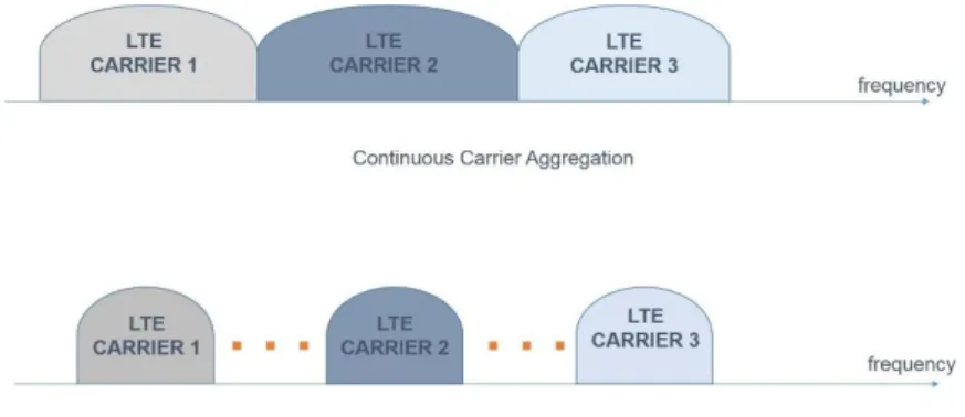
Carrier aggregation is one of LTE-A main features that gives this system the ability to reach 1 Gbps and 500 Mbps data rate for both downlink and uplink, respectively. 3GPP release 10 includes the deployment scenarios of carrier aggregation that the latter enables the mobile broadband operators to utilize their available spectrum resources to increase the data rates in LTE-A systems. Carrier aggregation supports very-high-data-rate transmissions and achieve up to 1 Gbps peak rate at downlink transmission for static and pedestrian mobile users, and 100 Mbps peak rate for mobile environment over wide frequency bands. Carrier aggregation method to increase data rate is by aggregating LTE components that called Carrier Components (CC) into continuous and non-continuous carrier(s). The component carrier can be consisted of 1.4, 3, 5, 10, or 15 or 20 MHz and five component carriers is the maximum number of aggregated carriers. Continuous and non-continuous carrier aggregation techniques are used when multiple available component carriers are adjacent to each other with a band that is greater than 20 MHz, and when multiple available component carriers are separated along the frequency band (different frequency band), respectively. Non-continuous carrier aggregation helps in achieving higher throughput and it improves carriers’ stability that has a different propagation environments. [42]
18
However, both carrier aggregation techniques supports LTE-A with many features such as spectrum efficiency, deployment flexibility, and backward compatibility that helps mobile broadband operators to upgrade their systems with a smooth system migration and maximal reuse of LTE releases in 8 and 9. [38, 39]
Figure 2.7 Carrier Aggregation Scenarios
2.4.3. Frequency Division Multiplexing
Frequency Division Multiplexing (FDM) is a communication method, where the available bandwidth is divided into a series of sub-bands, each of is called a carrier that carries voice or data signals. Frequency division method family has many members that are used for different communication techniques. Frequency Division Multiple Access (FDMA) is used in GSM, where it coordinates the accessing method among multiple users. Orthogonal Frequency Division Multiplexing (OFDM) is a digital multicarrier modulation method that is used in wireless communication systems. OFDM utilize the use of a large number of closely spaced orthogonal subcarriers that are transmitted in parallel, where each subcarrier is modulated with a conventional modulation scheme such as Quadrature Amplitude Modulation (QAM), and then the combination of subcarriers enables the data rates to be similar to the conventional single carrier modulation. OFDM has been used for a long time, but not for mobile communication; this due to the nature of OFDM that requires a high power processing to perform many Fast Fourier Transform (FFT) operations. Orthogonal Frequency Division Multiple Access (OFDMA) method offers a multiple access for users by dividing the available spectrum into a several channels, where the mentioned FDMA’s carriers are not orthogonal to each other. Coded OFDM (COFDM) is one of the members of OFDM family that refers to forward error correction at the phase of
19
transmission. Since the nature of OFDM is featured with its spectral efficiency and robustness to multipath fading, and its ability to provide a high data rate, the technology was recommended to be used for LTE systems in downlink communication.
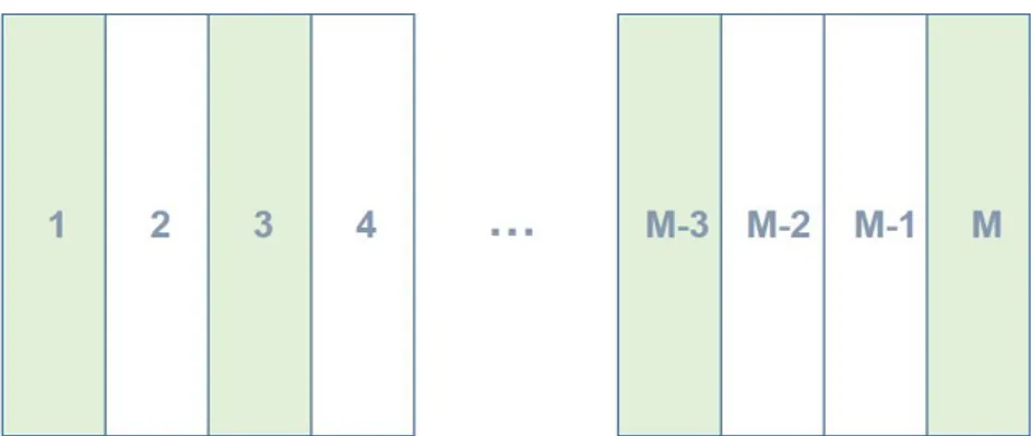
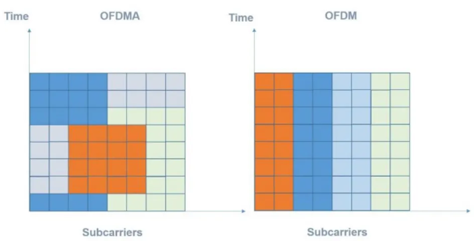
Figure 2.8 OFDM vs OFDMA Subcarrier Allocation
In figure 2.7, shows the users’ allocation on channels, where this technique separates the channels assigned among the users using TDMA. OFDMA transmits information on M orthogonal subcarriers, each operating bit rate of 1/M fold bit rate of the original signal, where this rate decrease helps the alleviation of multipath effect of the channel and reduces the equalizer complexity at the receiver side. In addition, OFDMA suffers from Doppler Shift (DF) that creates interference between carriers; moreover, the nature of OFDM requires a high Peak to Average Power Ratio (PAPR), that requires high transmission powers, and by that, it wastes mobile stations’ powers. A newer technology invented to protect this loss, where Single Carrier-FDMA (SC-FDMA) technology proposed to be used at the uplink part in LTE, where SC-FDMA spreads the energy of one subcarrier over a range of all subcarriers. [27]
2.4.4. LTE Network Architecture
In new proposed mobile broadband systems, the network architecture contains new features that are different from the previous systems’ architecture. In LTE’s network architecture, the name eNodeB corresponds to the base station that is connected directly to mobile stations, and controls the radio related functionalities
20
such as modulation/demodulation, channel coding/decoding, mobility management, ciphering/deciphering, data delivering, radio signal level measurements control, and resource control that consists of allocation and modification. eNodeB is connected to the Evolved Packet Control (EPC) via S1 interfaces that connects eNodeBs properly with the Serving Gateway (SGW) at the core network. X2 is the interface that connects the eNodeBs together that works in a meshed way. The reason behind having X2 interface is to minimize packet loss due to a user mobility among cells; as the UE crosses through a cell, an unacknowledged packets which are stored at the left-eNodeB queues can be forwarded to the entering-left-eNodeB through X2.
Figure 2.9 LTE Network Architecture
EPC is composed of several functional entities, for controlling communication along the network, the entities are Serving Gateway (SGW), Mobility Management Entity (MME), Packet Data Network Gateway (PDN-GW), and Home Subscriber Server (HSS). SGW is used at the EPC part, where it acts as the first interface at the EPS, receives and passes the UEs’ ingoing and outgoing traffic through the network. In addition, it is in charge of UEs mobility when a mobile station is handing over to another eNodeB. MME is the key control node for LTE access network, it is responsible for choosing UE’s SGW at both initial attach and at handoff process. Moreover, location management including location update and paging, activation/deactivation, authentication, security, roaming are the tasks of MME.
Similarly to SGW, Packet Data Network Gateway acts as the end point of the EPC towards packet data network such as internet; it provides users with IP addresses, policy enforcement for resource allocation and usage and packet filtering. In addition, PDN-GW plays an important role in system compatibility; it acts as an anchor for mobility between 3GPP and 3GPP2 technologies.
21
Home Subscriber Server is the HLR, and AuC of the 2G, 3G networks. HSS keeps information regarding user subscription, determines user ID, user privileges, and tracks users’ activities such as visited networks, Authorization, Authentication, and Accounting (AAA). MME and HSS are connected via interface called S6a that HSS enables the information provided by the HSS helps the management system finding the intended user in paging process. [17]
22
3. Home Base Stations: Femtocells/ Five Bar Coverage
This chapter addresses femtocell technology, evolution, and its network architecture in both UMTS and LTE technologies. The second part discuss a system model for interference mitigation method based on an adaptive power control algorithm designed for femtocell network that concerns about femtocell base stations’ data rate, and macrocell mobile station’s communication.
3.1. Femtocell Technology
Through the past years, the different demands has forced researchers to find a better communication methods; e.g. 3G was developed to provide high data rates, but due to the variant applications that increased the demands on a higher data rates, made 3G not sufficient for users; the reason that made research centers for having 4G. Moreover, indoor users suffers from having a low signal strength; the problem could be solved by mobile broadband operators by deploying more base stations to decrease the distance between the users and their attached base stations to guarantee a better data rate, capacity, and a battery power-saving for indoor users without the need of modification of uses’ handset devices. Unfortunately, this approach is infeasible and too expensive, the reason that made the researchers to think of a newer method to solve indoor users’ issue.
Home Base Stations or Femtocells, are a short ranged and low powered base stations, that uses a mature mobile technology, and operates in a licensed spectrum. Femtocells offers its users coverage and capacity and communication with the core network over an internet backhaul, with a low price. A full management by the mobile broadband operator that users can self-organize and manage is supported by femtocell. Femtocell base station offers indoor users an enough coverage to use in their indoor environment with a reasonable price, where they communicate with the network operator over DSL connection, Radio Frequency (RF) backhaul or cable modem [5].
23
Operators seek for a better coverage and capacity, when an area is suffering from a leak of resources, generally, the operators installs a base station to that area, and re-plan the network; in the case of using femtocell technology, the operators has no more to do that.
Deploying a femtocell guarantees indoor users to have a better data rate with a cheap price; also it reduces the burden of using the resources of other mobile users that are connected to the operator’s base stations (that in the deployment of femtocell are called Macrocell), which gives the macrocell users a better quality of service. Home base stations has the plug-and-play property, which means that they do not need any configuration at the installation part. UMTS femtocells are called Home Node B (HNB) that was published by 3GPP at release 8 where it use WCDMA technology for communication, while the LTE femtocells that was published in 3GPP release 9 are called Home evolved NodeB (HeNB) which uses OFDMA and SC-FDMA techniques for communication as for downlink and uplink, respectively.
3.2. HNB and HeNB Network Architecture
Since the technology of femtocell is developed to be used by customers randomly, and the number of activated HNBs is numerous, a scalable network architecture has to be found to serve them properly. Home Node Base-station (HNB) is the name of femtocell that is used in UMTS, where Home evolved Node Base-station (HeNB) is the unit used in LTE systems. The femtocell has changed the network architecture of both UMTS and LTE systems; conventional systems cannot operate HNB or HeNB, the thing that let the network architecture and integration of both mentioned technologies has to be modified.
The Evolved Packet Core (EPC) part includes many Mobility Management Entities (MMEs), Packet Data Network Gateway (PDN-GW), and a Home Subscriber Server (HSS). MME is the core of the EPC; where it is connected to both enodeBs and HeNB-GWs, and it is responsible for signaling of UE, managing the UE’s connection, authentication, and security. With the help of Serving Gateway (S-GW) sub-entity that included at the MME part, S-GW provides UEs with roaming, paging, and handover services. HSS is a database that has records for each subscriber; the concept behind HSS is not new; it is used within the name home location registry, that HSS is defined as a database where subscribers’ profiles are stored and updated. In
24
addition, HSS acts as an authentication center that facilitates the generation of security information from user’s identity keys.
Evolved-UMTS Terrestrial Radio Access Network (E-UTRAN) of LTE system consists of eNodeB (eNB) that corresponds to the conventional base station, and femtocells. Femtocells involves UE, HeNB, and HeNB-GW. HeNBs supports its users with the same privileges that enodeBs does, where the procedure taken by MME at the EPC part with the enodeB is the same as for the HeNB. However, the new entity that now involved at the femtocell part called HeNB-Gateway (HeNB-GW) that acts as a concentrator. The role of HeNB-GW is to make the HeNB appearance as an eNB to the MME side that exists at the EPC part, where it also provides the appearance of MME to the HeNB. HeNB Policy Function (HeNB PF) is an embedded entity that concerns about user type, access mode of HeNB’s current load, distribution of signaling and data, supports the registration of HeNB and UE, makes decisions according to HeNB’s state regarding whether the admission quest could be accepted or not. [43, 46]
Figure 3.1 HeNB Network Architecture
UE communicates within the connected HeNB by radio frequency through Uu interface that uses SC-FDMA and OFDMA for uplink and downlink, respectively. HeNB communicates with HeNB-GW through S1 interface, and HeNB-GW uses the same interface to communicate with the MME/S-GW at the EPC part. In LTE systems, the S1-Access Part (S1-AP) interface is designed to control message exchange procedure between eNB and MME, where it consists of a set of elements such as S1
25
setup, Paging, Error indication, Trace. However, for HeNB, the interface chosen for HeNBs uses S1 interface and S1-AP protocol, which are the same used at the eNB part, but this element has modifications on one of its sub elements that differs from the ones used at the eNB; this element is Element Procedure (EP).
EP represents the interaction function between eNB/HeNB and MME for initiating the communication messages and reply messages, where two types of EP (type1) and (type 2) exists; these types represents a reply message with a response of success of failure, and no response message, respectively. When the HeNB is turned on, the HeNB configure itself using HeNB Management System (HeNBMS) using TR-069 protocol. A setup procedure is also done at the point that uses Transfer Network Layer Stream Control Transmission Protocol (TNL SCTP) association within the HeNB-GW or with the MME, whether the HeNB-GW topology is not used, then the HeNB is considered as registered at the MME that resides in the EPC part. The purpose of this registration is important; it informs the availability of the HeNB and enables MME to support the node with a connection within the core network [38]. UMTS femtocell base station is called HNB; where 3GPP has defined a special Iuh interface and an application protocol Home Node Base-station
Application Part (HNBAP) that the latter consists of a set of procedures such as HNB registration/ deregistration procedure. 3GPP has defined a special Iuh protocol for HNBs, where the main protocols are RANAP, SCTP, HNBAP, and RUA. RANAP protocol provides signaling services between HNB and the core network that fulfills the Radio Access Network Relocation (RANA) and Radio Access Bearer (RAB), management, paging, and transport between mobile station and the core network. HNBAP conducts HNB-GW discovery, HNB and UE registration, where SCTP represents the transport protocol operating on top of a connectionless packet network. RANAP User Adaptation (RUA) transfer RANAP messages between HNB and HNB-GW through five procedures. The first procedure is called connect, where this procedure is responsible for carrying the RANAP user equipment message from HNB to HNB-GW. The second procedure is called direct transfer that lets the RANAP flows of messages between nodes. The third procedure is called disconnect, where this procedure terminates the connection between nodes. The fourth
procedure is called connectionless, where this procedure is responsible for
26
is called error indication, where it reports detected errors in an incoming messages. Second, third, fourth, and fifth procedures are all initiated by the HNB or HNB-GW.
Figure 3.2 HNB Network Architecture [9, Figure 3.1]
In UMTS femtocell network architecture, the term Femtocell Access Point (FAP) refers to HNB that also provides a gateway within the name FGW that refers to HNB-GW that provides the communication for the femtocell to the Radio
Network Controller (RNC). However, Home NodeB Subsystem (HNS) is the entity that includes the HNB, and HNB-GW that integrates the functionality of NodeB and RNC by connecting the UTRAN network with the backhaul network. Handover procedure is important to be studied for femtocell; in femtocell handover, the handover goes through two phases to make it feasible for the UE and the core network. The first phase is called the handover phase that consists of information gathering, and handover decision, while the handover execution phase is the second phase. During the information gathering phase, the HNB collects the needed
information regarding the handover candidates and authentications are also required for security related purposes, where handover decision phase gives the handover candidate decision determination. However, when a mobile station that uses a HNB decides to handover to macro station (NodeB), the difference relies in Radio
Resource Control (RRC), that represents the difference in the base station that used to serve the mobile station, with the other base station that is limited with its radio resources, due to its availability to further amount of users.
![Figure 2.1 GSM Network Architecture [41, Fig2.1 (a)]](https://thumb-eu.123doks.com/thumbv2/9libnet/4337865.71700/28.892.274.723.547.766/figure-gsm-network-architecture-fig.webp)


![Figure 3.2 HNB Network Architecture [9, Figure 3.1]](https://thumb-eu.123doks.com/thumbv2/9libnet/4337865.71700/43.892.242.655.204.415/figure-hnb-network-architecture-figure.webp)