T.C.
ISTANBUL AYDIN UNIVERSITY INSTITUTE OF GRADUATE STUDIES
INVESTIGATION OF DIFFERENT METHODS FOR LOAD SHARING AND POWER MANAGEMENT IN A HYBRID MICRO-GRID
M.Sc. THESIS
Hasibullah Shams
Department of Electrical & Electronic Engineering Electrical and Electronics Engineering Program
T.C.
ISTANBUL AYDIN UNIVERSITY INSTITUTE OF GRADUATE STUDIES
INVESTIGATION OF DIFFERENT METHODS FOR LOAD SHARING AND POWER MANAGEMENT IN A HYBRID MICRO-GRID
M.Sc. THESIS
Hasibullah Shams (Y.1613.300019)
Department of Electrical & Electronic Engineering Electrical and Electronics Engineering Program
Advisor: Prof. Dr. Murtaza FARSADI
DECLARATION
I hereby declare that all information in this thesis document has been obtained and presented in accordance with academic rules and ethical conduct. I also declare that, as required by these rules and conduct, I have fully cited and referenced all material and results, which are not original to this thesis.
FOREWORD
In the name of Almighty ALLAH, the most merciful the most gracious, and may Allah’s Peace and blessing be upon our Prophet MUHAMMAD P.B.A. Alhamdulillah after thanking to almighty Allah our creator, I would like to thank my Respectable Family specially My Father and Mother who raised me to become a good person, they always supported me and believed at me, Encouraged me and gave me the strength while I was totally lost. They were patient during my mistakes and my bad times. Today what I have accomplished is because of their effort. I hope I can make them proud and return even some of what they gave me during their Entire lives.
I would like to thank my thesis advisor Prof Dr. MURATZA FARSADİ for his guidance, support, and help during my work in the thesis. I thank him for everything I learned from him.
I thank all my teachers starting from my school time until today as they had great influence on me and made me love education and I hope I can become one day a good teacher as they were
April, 2020 Hasibullah Shams (Electrical and Electronics Engineer)
TABLE OF CONTENT Page FOREWORD ... v TABLE OF CONTENT ... vi ABBREVIATIONS ... viii LIST OF FIGURES ... ix LIST OF TABLES ... xi ABSTRACT ... xii ÖZET ... xiii 1. INTRODUCTION ... 1
1.1 Issues Raised In Solar Microgrids ... 2
1.2 Operation Method ... 3
1.2.1 Maximum power point tracking (MPPT) ... 3
1.2.2 Energy storage ... 4
1.2.3 The structure of the solar converters ... 5
1.2.4 Connection of batteries and PV panels ... 6
1.2.5 Control and power management of the micro-grid ... 6
1.2.5.1 Centralized and decentralized methods. ... 7
1.2.6 Grid structure ... 8
1.2.6.1 Goals and approaches of the thesis ... 8
1.2.6.2 Structure of the thesis ... 8
2. DECENTRALIZED ACTIVE POWER MANAGEMENT IN SINGLE-PHASE HYBRID SINGLE-SOURCE MICROGRID ... 10
2.1 Introduction ... 10
2.2 An Approach Of Decentralized Active Power Management Method ... 11
2.3 Decentralized Active Power Management In Microgrid ... 16
2.3.1 Incremental PV converter control ... 20
2.3.2 Battery boost converter control ... 22
2.3.3 Inverter control ... 24
2.3.3.1 Active and reactive power output calculation ... 24
2.3.3.2 Active and reactive power control ... 25
2.3.3.3 Virtual impedance ... 25
2.3.3.4 Voltage control ... 26
2.3.3.5 An overview of droop method ... 29
2.3.4 General modes of micro-grid performance in the proposed method ... 31
2.3.5 The performance status of each micro-grid unit in the proposed method. 36 3. DECENTRALIZED POWER MANAGEMENT IN SINGLE PHASE / THREE PHASE HYBRID MICROGRID ... 45
3.1 Introduction ... 45
3.2 Decentralized Active Power Management In Micro-Grid ... 47
3.2.1 General modes of grid operation and operating status of each micro-grid unit ... 49
4. EXPERIMENTAL RESULTS ... 53
4.1 Main Circuit ... 53
4.2 Proposed Methodology ... 53
4.3 Working of PV subsystem 1 ... 54
4.4 Methodology Description ... 55
4.5 Operation of battery System of Subsystem 1 ... 55
4.6 Battery voltage and SOC of Subsystem 1 Description ... 56
4.7 Operation of PID controller: ... 57
4.8 Operation of PWM Inverter ... 58
4.9 Main Circuit of Subsystem 2 ... 58
4.10 Working of PV subsystem 2 ... 59
4.11 Methodology Description ... 60
4.12 Operation of battery System of Subsystem 2 ... 61
4.13 Operation of PID controller ... 61
4.14 Experiments and Results ... 64
5. CONCLUSION AND RECOMMENDATIONS ... 66
5.1 Conclusion ... 66
5.2 Innovations In The Thesis ... 67
5.3 Suggestions For Further Research ... 68
REFERENCES ... 69
ABBREVIATIONS
AC : Alternation Current DC : Direct Current
DERS : Distributed Energy Resources DG : Distributed Generation EMS : Energy Management System ESS : Energy Storage System ESUs : Energy Storage Units
MG : Microgrid
MPPT : Maximum Power Point Tracking
MS : Microsystem
PCC : Point of Common Coupling PID : Proportional Integral Derivative PSF : Power Signal Feedback
PV : Photovoltaic Panels PWM : Pulse Width Modulation
SC : Solar Cell
SOC : State of Charge
SOGI : Second Order Generalized Integrator SPU : Single Phase Uni
THD : Total Harmonic Distortion TPU : Three Phase Unit
LIST OF FIGURES
Page
Figure 1.1: The P-V curve at different radiation levels for a solar cell. ... 4
Figure 1.2: The P-V curve at partial shade conditions. ... 4
Figure 2.1: Typical single-phase MG structure. ... 10
Figure 2.2: Frequency control method in [48]. ... 12
Figure 2.3: Micro-grid studied in [48]. ... 12
Figure 2.4: The micro-grid studied in [49]. ... 13
Figure 2.5: The microchannel studied in [36]. ... 13
Figure 2.6: Block diagram of decentralized control of each microgrid unit ... 18
Figure 2.7: Conditions of Changing the Status of Each MG ... 20
Figure 2.8: Control method of PV incremental converter in different situations ... 21
Figure 2.9: Battery boost converter control methods in different situations ... 23
Figure 2.10: Method for determining the Battery Authorized Charging Power in situation 2,3. ... 23
Figure 2.11: OSG perpendicular signal generation by SOGI-OSG method ... 25
Figure 2.12: Inverter output voltage control loop ... 26
Figure 2.13: The graph chart of 𝑮𝒄𝒔 with harmonic offsets of 3,5 and 7. ... 27
Figure 2.14: Inverter closed-loop control diagram ... 27
Figure 2.15: table chart of the closed loop conversion function of 𝑮𝑽𝒓𝒆𝒇 = 𝑽𝒄(𝒔)𝑽𝒓𝒆𝒇(𝒔) ... 28
Figure 2.16: System output impedance in the frequency domain ... 29
Figure 2.17: The equivalent circuit of a distributed generation unit connected to a common bus ... 29
Figure 2.18: Characteristic 𝒑 − 𝒇 a microgrid composed of two different hybrid status ... 43
Figure 2.19: Characteristic displacement 𝒑 − 𝒇 and working point due to decrease in maximum 𝑷𝑽 power of 𝒖𝒏𝒊𝒕 𝟏 ... 44
Figure 3.1: Single Phase / Three Phase Hybrid Network ... 45
Figure 3.2: The single-phase / three-phase hybrid micro-grid considered in this thesis ... 46
Figure 3.3: Inverter control diagram of three phase units ... 48
Figure 3.4: Criteria for transition between the states in each unit in the MG. ... 51
Figure 4.1: subsystem 1 Complete Layout... 53
Figure 4.2: Circuit of PV subsystem 1 ... 54
Figure 4.3: power generated by PV solar panels of subsystem ... 55
Figure 4.4: Charging and discharging of Battery System ... 56
Figure 4.5: Battery voltage and SOC of Subsystem 1 ... 57
Figure 4.6: Power Control by PID Controller ... 58
Figure 4.7: PWM Inverter ... 58
Figure 4.8: subsystem 2 PV Layout ... 59
Figure 4.10: power generated by PV solar panels of subsystem ... 60
Figure 4.11: Battery voltage and SOC of Subsystem 2 ... 61
Figure 4.12: Power Control by PID Controller ... 62
Figure 4.13: Battery voltage and SOC of Subsystem 3 ... 63
Figure 4.14: Battery voltage and SOC of Subsystem 4 ... 63
Figure 4.15: Voltages of all the subsystems ... 64
Figure 4.16: Voltages of all the subsystems ... 64
Figure 4.17: Currents of all the subsystems ... 64
LIST OF TABLES
Page Table 2.1: Summary sof the different status of a micro-grid unit ... 19 Table 1.3: Summarizes The Different States Of A Three-Phase Micro-Grid Unit ... 50
INVESTIGATION OF DIFFERENT METHODS FOR LOAD SHARING AND POWER MANAGEMENT IN A HYBRID MICRO-GRID
ABSTRACT
A grid consists of a set of distributed generation units, energy storage resources, communication links and local loads, and can operate in two modes connected to the grid and separate from the grid. Power management and load sharing between grid units in a separate mode can be in both centralized or decentralized. In a decentralized way, with decentralized method is preferable due to local measurements, and the lack of a fast communication link and reliability.
In this thesis, a micro grid consisting of distributed generation units of a solar type and a storage source of a kind of battery is considered that can be connected independently (by separate inverters) or in combination of PV / battery (by a common inverter) to the grid. The purpose of this thesis is to provide a power management method and a decentralized load distribution for offshore grids, consisting of a variety of independent solar panels, independent batteries, and solar / battery combinations. In the proposed method, the operation of each grid unit is divided into six states and, depending on the different conditions, each unit operates in one of these situations. The control of the solar cells, the battery and the inverter unit vary according to the performance status. In this method, only the local measurements of the conditions of change are examined. The automatic balancing of battery charge rates and the optimal use of solar array capacity to supply power and charge the batteries is one of the most important features of this method. This method is firstly investigated for a single-phase grid, and then generalized to a single-phase / three-phase mixed-grid grid in which single-phase units are connected to different phases of a three-phase grid. Power transmission from phase to another phase and supplying the charge or charge power of a phase from another fuzzy is a feature of this method in single-phase / three-phase combination mode.
Keywords: Microgrid, decentralized power management, hybrid PV battery units,
HİBRİT MİKRO GRİDDE YÜK PAYLAŞIMI VE GÜÇ YÖNETİMİ İÇİN FARKLI YÖNTEMLERİN İNCELENMESİ
ÖZET
Şebeke, bir dizi dağıtılmış üretim ünitesi, enerji depolama kaynakları, iletişim bağlantıları ve yerel yüklerden oluşur ve şebekeye bağlı ve şebekeden ayrı olarak iki modda çalışabilir. Ayrı bir modda Mikro Şebeke üniteleri arasındaki güç yönetimi ve yük paylaşımı hem merkezi hem de merkezi olmayan olabilir. Merkezi olmayan bir şekilde, yerel ölçümler ve hızlı iletişim bağlantısının ve güvenilirliğinin olmaması nedeniyle merkezi olmayan yöntemle tercih edilir.
Bu tezde, Microgrid bir güneş türü ve (ayrı inverter) veya PV / batarya ile bir kombinasyon halinde, bağımsız bir şekilde bağlanabilir olduğu düşünülmektedir bataryanın bir türden bir saklama kaynağı dağıtılmış üretim birimlerinin oluşturduğu (ortak bir inverter tarafından ). Bu tezin amacı, çeşitli bağımsız güneş üniteleri, bağımsız batarya ve güneş / batarya kombinasyonundan oluşan ağ mikro şebekeleri için yeni bir merkezi olmayan güç yönetimi ve dağıtım yöntemi sağlamaktır. Önerilen yöntemde, her bir şebeke ünitesinin çalışması altı duruma bölünür ve farklı koşullara bağlı olarak, her birim bu durumlardan birinde çalışır. Güneş pillerinin, akünün ve evirici ünitesinin kontrolü performans durumuna göre değişir. Bu yöntemde, değişiklik koşullarının sadece yerel ölçümleri incelenir. Pil şarj oranlarının otomatik olarak dengelenmesi ve pilleri beslemek ve şarj etmek için güneş enerjisi dizisi kapasitesinin optimum kullanımı bu yöntemin en önemli özelliklerinden biridir. Bu yöntem ilk olarak tek fazlı bir şebeke için araştırılır ve daha sonra tek fazlı ünitelerin üç fazlı bir şebekenin farklı fazlarına bağlandığı tek fazlı / üç fazlı karışık ızgaralı şebekeye genelleştirilir. Fazdan başka bir faza güç iletimi ve bir fazın başka bir bulanıktan şarj veya şarj gücü sağlanması, bu yöntemin tek fazlı / üç fazlı kombinasyon modunda bir özelliğidir.
Anahtar Kelimeler: Mikro şebeke, merkezi olmayan güç yönetimi, hibrit PV pil
1. INTRODUCTION
Due to the lack of fossil fuels and related environmental issues, the attractiveness of using renewable energy sources or renewable energies are increasing day by day. These sources are often exploited as distributed generations units. It is possible that distributed generation units operate in two ways both: connected to the grid and separated from the grid or islanded mode. In islanded mode; the distributed generating units have no connection to the main grid and feed local loads. In this case, using energy -saving sources such as batteries, the balance between production and energy consumption is established. In grid connected mode, the distributed generating units are connected to the main grid and the power is injected into the grid. [1]–[4]. According to current standards, the distribution network for the operation of the grid-connected distributed generation systems, in the event of disconnection of the main grid, the distribution sources must be separated from the grid within a maximum of 2 𝑠𝑒𝑐𝑜𝑛𝑑𝑠 [5]. This way, loads placed in the disconnected area of the grid, where there is also a scattered power supply, will remain powerless, and the scattered power source will not be powered until the main grid is reconnected. To use the capacity of distributed generation units at the time of disconnection of the main grid, the idea of using a micro -grid has been proposed. A micro grid consists of a set of distributed generation units, energy storage resources, communication links, and local loads. Distributed generating units are usually connected to the grid using an electronic power converter which provides much flexibility in controlling and managing the micro -grid. In a micro-grid, hardware and resource control systems are designed to be able to inject power in both connected and separate states [6]. Due to the micro-network (MG) capability of continuity of power supply when the main micro-network is disconnected, the most important feature of the micro-network (MG)is its significant increase in reliability compared to conventional networks (Grids). As a result, the use of microgrids in power supply to critical and sensitive loads is increasing steadily, and as the world continues to develop into more energy
efficient storage systems and lower prices, the world's electricity distribution networks will move toward microcontrollers (Microgrids) . Distributed generators (DG) in terms of technology can be into three categories as Fossil fuels, Renewable energy and Energy storage devices. Gas turbines and microturbines use fossil fuel gas and can be used to generate electricity and heat at the same time. Renewable energies include Wind and Solar (photovoltaics), Geothermal and other types and their use is increasing day by day due to the lack of environmental pollution. Batteries, supercapacitors, and water storage dams are used as energy storage [7]. Among renewable energy sources, solar energy has received a great deal of attention due to the need for non -mobile mechanical installations, pollution free energy generation process and low maintenance cost [8]. The most important factor in preventing the spread of solar energy use is its high initial cost but given the day-to-day technology of solar cells and the reduced cost of manufacturing and increasing their efficiency, the introduction of new structures at lower cost and higher efficiency for solar converters. And with the significant increase in solar system reliability, solar energy is expected to make up a significant share of electricity generation [3]. According to the European Solar Associatio1 [European Photovoltaic Industry Association(www.epia.org)] in the year 2015 the total installed solar capacity worldwide has exceeded 200 GW and solar power is capable of accounting for 15% of Europe's total electricity generation by 2030. Also, if only 0.7% of Europe's land is covered by solar cells, Europe's total elect ricity demand will be met. Due to the expansion of the use of small domestic solar units in the distribution network as well as the necessity of using batteries alongside them to prevent severe fluctuations due to the variability of solar power produced by future standards is not unthinkable soon to be able to utilize micro-grids for home solar panels. Therefore, the overall aim of this thesis is to present new control methods for solar-powered micro-grids.
1.1 Issues Raised In Solar Microgrids
There are various issues in PV solar micro-grids, each of which has been devoted to extensive research. Some of these issues exist in all micro -grid networks, whether solar or other sources, and some are solely for PV solar
micro-grids. These issues can also be addressed in two general categories at the whole micro-network level or at the level of each micro-grid unit.
1.2 Operation Method
Some Micro-grids are only used as islanded separately from the grid, while others are used in both connected and isolated states. When connected to the grid, the voltage and frequency at the point of common coupling (PCC) are imposed by the main grid and the micro-grid controller controls the active and reactive power exchanged with the main grid. In islanded mode, because the micro-grid has no connection to the main grid, the amplitude and voltage frequency of the micro-grid should be determined automatically by the distributed generation or energy storage sources within the micro -grid.
1.2.1 Maximum power point tracking (MPPT)
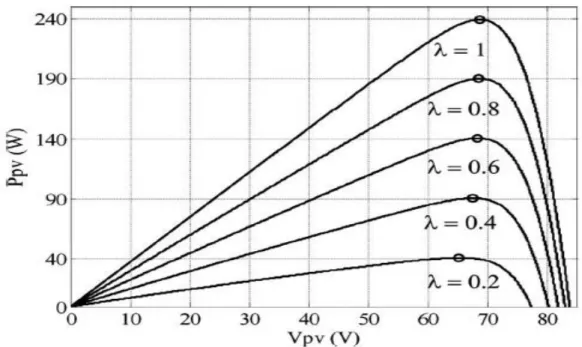
Since the energy of the PV cells varies in different conditions and depends on the environmental conditions and the amount of radiation, the maximum power point tracking (MPPT) methods must be used to extract the cells at any time as much as possible. There are many methods for tracking the maximum power point (MPPT) that use a particular solar cell's voltage-voltage curve [8]–[13]. The curve at different radiation levels for a particular solar panel is shown in Figure 1-1. In most of these methods, the maximum power point is detected by changing the solar cell voltage and observing the power changes.
The most important debate in the (MPPT) is tracking the maximum power point in partial shadow conditions. These conditions occur when part of the cells that are aligned or parallel to each other are in the shade, resulting in a P -V curve such as Figure 1-2 having more than one local maximum point. In this case, algorithms must be used to find the local maximum point with the maximum value (absolute maximum).
Figure 1.1: The P-V curve at different radiation levels for a solar cell.
Figure 1.2: The P-V curve at partial shade conditions. 1.2.2 Energy storage
Due to the variability of the energy produced by a PV solar cell, in some applications, both the grid connected and separated (stand -alone) require an energy storage element such as a battery. The use of energy storage poses
challenges in how to manage power between the solar cell, energy storages and the consumer [14]–[19]. In off-grid applications, given that solar cell energy is zero during the night and highly variable during the day due to radiation conditions and environment temperature that is, the energy storage element such as the battery must be used to continuously supply the local load required. Under such circumstances, each time the solar energy exceeds the load, the surplus energy is stored in the battery, and each time the solar energy is lower than the required load, the rest is supplied from the battery. In some applications to increase system dynamics, in addition to the battery, the capacitor 1 is also used to respond to rapid power changes. In some applications connected to the grid, the storage element is used to prevent large variations injections to the grid. Due to the ever-expanding use of solar energy in the power system, large and rapid changes in grid energy may cause problems for the power system. You can use a power saver like a battery to solve these problems.
1.2.3 The structure of the solar converters
In a separate mode from the grid, since the battery is usually used, the structure must be used which has two input ports for connecting the solar cell and the battery. This can be achieved through a two-class structure including inverter and dc-dc converter with two input ports, or through newer structures that allow two or more inputs to be connected to a single-class structure. Two important classes of new structures, the cascade multilevel inverter (CHB)1 (Cascade H-Bridge)
[15], [20] and Z-Source Inverters [21], [22]. When connected to the grid, if the battery is used, the same issues are mentioned as in separate from of the grid. But the most important issue in this case is the issue of leakage current due to the scattering capacitance between the positive and negative terminals of the solar cell with the earth. If the transformer is used in the solar converter - whether the high frequency transformer in the DC-DC converter class or the low frequency transformer in the converter output - there will be no leakage current problem. But due to the bulk of the transformer, the higher cost and the relatively lower efficiency of the transformer structures, the market trend is towards using non-transformer structures. In this type of structure, specific structures should be used to prevent leakage current, or only certain s pecific
switching algorithms (such as bipolar switching in single-phase H-bridge converter) should be used [23]–[27]. The type of filter used in the converter is determined by application and can be of type L, LC, LCL or can be more complex structures like LLCL [28]–[30]. However, the LC filter is usually used in off-grid mode and the L or LCL filter in grid connected mode. Due to the better performance of the LCL filter in reducing the ripple switch current and its better dynamics, this type of filter is used more. But the most important proble m LCL filter which is a tertiary filter, there is resonance. If this resonance is triggered by the frequency response of the LCL filter by a control loop or external perturbations such as network voltage perturbations, it may cause perturbations in the output current or even system instability. If this resonance is triggered by the frequency response of the LCL filter by a control loop or external disturbances such as grid voltage perturbations, it may cause disturbances in the output current or even system instability. Two main methods of passive damping and active damping are used to attenuate this resonance. In the passive damping method, a resistor with series capacitors is filtered. There are many ways to enable active attenuation, including multilevel control and active attenuation based on software filters [29], [31]–[35].
1.2.4 Connection of batteries and PV panels
Batteries and solar arrays can be connected to the micro-grid in two ways [18], [36].
1- Standalone: In this case, the batteries and solar arrays are connected to the micro-grid by two separate inverters.
2- Combined: In this case, the battery and the solar array have a common inverter, each connected to a common dc link by a dc-dc converter. The advantage of this structure is its lower cost and higher efficiency.
1.2.5 Control and power management of the micro-grid
In grid-connected mode, the usual way of controlling renewables like solar is to do so, as all sources generate maximum power and are injected into the main grid. But considering expanding the use of renewable resources, other functions such as reactive power control, energy management during hours of the day to
reduce the pressure on the main grid, and… are created for the micro-grid while its connected to the main grid. For example, during the daytime hours where consumption is low, generated energy by resources can be stored to the batteries and at the peak hours of consumption, by using the energy stored in the battery we can reduces the pressure on the main grid and reduces the maximum power to its medium power ratio. for this purpose, an overhead central controller or (Tertiary Controller) can be used to manage the actual and reactive power exchanged with the main grid. other functions, such as active filtering of nonlinear loads and power factor correction, can also be added to existing micro-grid. The most important challenge in the island state is how to allocate power between resources and their energy storage elements and their optimal management. Due to the absence of the main grid, the control of the amplitude and frequency of the voltage and the active and reactive power supply of the local loads is the responsibility of the micro-grid. In general, the power management method is divided into two categories:
1.2.5.1 Centralized and decentralized methods.
• Centralized Method: In this method, all information on energy sources, energy storage and loads in the grid is transmitted to a central con troller via communication links and the central controller determines the amount of production or storage per unit. The most important problems with this method are:
• High cost and complexity due to the use of high bandwidth communication links.
• Low reliability due to dependency on proper communication links performance. In this case, if the communications links are broken, the power management will not work properly and may cause the entire network to fail.
• Adding or removing a unit in the grid requires changes to the central controller.
• Decentralized Method: In this method there is no central controller and all units (production, storage and controllable loads) are controlled independently by local measurements only, and no other unit information
is required. In this method the role of each of the distributed units is the same as the other units, and none of them have a more central role. It also provides greater reliability due to the lack of need for a central controller and communications links. It is worth to mention that in a decentralized method, a central controller with a low bandwidth link can be used to improve system performance, but unlike the centralized method, communication link failure does not cause system failure.
1.2.6 Grid structure
Depending on the needs of the micro-grid and types of loads available, the micro-grid structure can be in one of phase, three-phase, or a single-phase / three-single-phase combination. In the hybrid structure, single-single-phase loads and generating units are connected to different phases of a three -phase micro-grid. 1.2.6.1 Goals and approaches of the thesis
The purpose of this thesis is to present a new decentralized method of Active power management and load distribution in grids which are separate from the solar grid. Unlike previous research, the proposed method is not limited t o micro-grids consisting solely of solar and battery independent units, but it is also applicable to micro-grids consisting of a variety of PV, independent batteries, and combined PV / battery units. This method maximizes solar power usage and the charge distribution between units is such that over time, the charge status of all the batteries in the micro-grid is balanced. The basis of the proposed method is a generalized Drupal method that changes its coefficients according to different performance states. Droop method is used to divide the reactive power.
1.2.6.2 Structure of the thesis
In the second chapter, the single-phase micro-grid is considered separately from the hybrid source network and details of the decentralized power management method are presented. This chapter describes the general modes of micro-grid operation, the different operating conditions of each micro -grid unit, how to control the batteries, PV solar and units per unit status of the inverters, the conditions for switching per unit and the startup algorithm for each unit are explained. Also effect of the impedance of the line connecting units on power
management is also investigated. At the end of the chapter, simulation and practical results are presented for a single-phase micro-grid consisting of three hybrid units. In Chapter three, the proposed method is extended to a single -phase / three--phase hybrid micro-grid. In this chapter, other conditions that do not exist in single-phase units are presented for the three-phase units and the transfer of automatic power from phase to phase is examined. At the end of the chapter, simulation and practical results are presented for a micro -grid consisting of a three-phase unit and two single-phase units connected to two phases of a three-phase unit. finally, in the fourth chapter, the results of the thesis are summarized and suggestions for further work are presented
2. DECENTRALIZED ACTIVE POWER MANAGEMENT IN SINGLE-PHASE HYBRID SINGLE-SOURCE MICROGRID
2.1 Introduction
The purpose of this chapter is to present an active power management and decentralized load distribution method for a single-phase micro-grid separate from the grid with different solar, battery and solar / battery units, such as shown in figure 2-1.
Figure 2.1: Typical single-phase MG structure. This microgrid consists of three types of units:
1. Independent Solar (PV) Unit: In this type of unit, a set of solar cells are connected to a dc inverter link by a one-way incremental converter. 2. Stand-alone Battery Unit: In this type of unit, a set of batteries are
connected to the inverter dc link by a two-way adapter converter.
3. Solar / Battery Combined Unit: In this type of unit, the solar cells are connected to a common dc link by a one-way adapter and the battery by a two-way adapter. The advantage of this structure is the use of two separate inverters to connect solar cells and batteries, reducing the cost of components and increasing efficiency due to the possibility of direct battery charging by the solar cell [18], [36], [37].
In a separate mode from the grid, the purpose of power management is to divide the load power between the various units, considering the amount of solar power generation and state of charge of the (SOC) battery units [38], [39].a Centralized power management [40]–[45] or Decentralized power management techniques can be used for this purpose [36], [46]– [51]. Because of the dependence of the telecommunications link between the units, the reliability of the centralized methods is less, and their complexity is higher [49], [52]. In this section, only decentralized active power management techniques are presented for separate micro-networks and finally a new approach is presented. Given that the focus of this thesis is on active power management, the common method presented in the papers has been used to divide reactive power.
2.2 An Approach Of Decentralized Active Power Management Method
The hybrid source systems provided in the article [46], [53]–[57] are only for grid-connected applications. Also, the hybrid source systems presented in the single unit [54], [55], and power management within a single unit that feeds its local load are investigated. İn [47] a micro-grid consisting of one battery unit and several solar units is provided. In the proposed method as a Master/Slave, the battery unit plays a major role and communicates with the PV units and controllable loads by controlling the network frequency according to its SoC. The method of this relation is illustrated in Figure 2-2. In this method, when the battery SoC is allowed in the range, the frequency is controlled at the rated
frequency. In more SoCs, indicating that the battery has less capacity to absorb excess PV power, the frequency is linearly increased to reduce the low power PV units produced. When the SoC reaches its maximum, the frequency reaches its maximum frequency and the PV units are completely cut off. The same method is used to phase out controlled loads when the SoC of the battery is reduced outside the permitted range.
Figure 2.2: Frequency control method in [48].
One of the biggest disadvantages of this method used in SMA inverters is the possibility to use only one battery unit and this method cannot be used if there are more battery units in the micro-grid. Similarly, the method presented in [46], only applies to one battery unit. In [48], a micro-grid consisting of a single wind turbine unit and a single battery unit is shown in Fig. 2-3, which are spaced apart from each other.
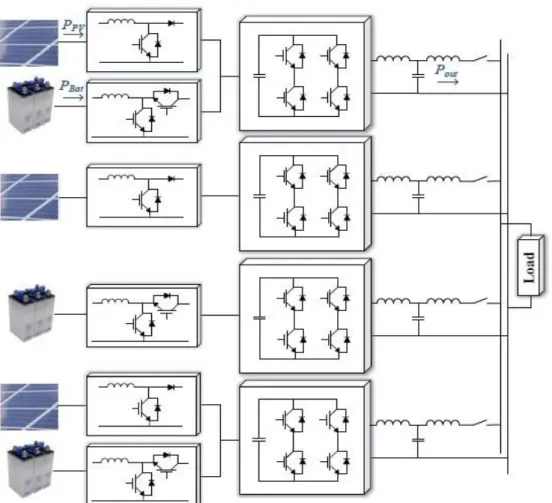
In [49], microbeads consisting of several standalone solar units and several standalone battery units are considered in figure 2-4 and a method for power management is presented.
Figure 2.4: The micro-grid studied in [49].
Figure 2.5: The microchannel studied in [36].
In this way, when a battery unit reaches its minimum SoC, that unit reduces its frequency by transferring more power from the batteries with a higher SoC.
Conversely, when a battery unit reaches its maximum SoC, that unit transmits power to batteries with less SoC by slightly increasing its frequency. Whenever all the batteries reach the maximum SoC, the frequency increases to the maximum frequency. In this case, the power of solar units should be reduced. The disadvantages of this method are the transfer of energy from one battery to another which reduces the overall efficiency of the system due to battery charge losses. Similarly, the methods proposed in [50] and [51] apply only to microgrids consisting of standalone battery units and PV.
In [36] a method for controlling a solar / battery unit connected to a microcontroller controlled by the Drop method is presented. This method assumes that a hybrid unit is connected to the microchannels controlled by a simple drop method and their source is unknown. The battery in the hybrid unit is responsible for supplying the load when other units in the micro-grid reach their maximum power. The application of this method is solely for the micro -grid consisting of only one hybrid unit. As seen in the literature review, the methods presented so far for managing microgrid power are applicable only to microgrids having one of the following modes:
1. - Only consist of one standalone battery unit and several standalone solar units.
2. Consist of several independent battery units and several independent solar units.
3. Only have one combination of solar / battery unit.
Until now, there is no decentralized way to manage load distribution in micro -networks containing multiple hybrid units. The main challenge in this type of micro-grid is that the PVs operate as far as possible at the m aximum power point, the charge and discharge of the batteries are properly managed, the battery can be recharged from the PV of other units, reducing the PV power if needed Units should be balanced, and all these issues should be decentralized and purely local measurement. In this thesis, an active power management and charge sharing method for separate micro-networks is presented which, unlike the methods presented in previous research, is not limited to micro -networks consisting of independent battery units and PVs and can be implemented in
micro-networks of different types. It has PV units, batteries and one or more combination units.
The method presented in this thesis addresses all the above challenges without the need for a link between units and without knowing the amount of load, and has the following characteristics:
• Power management is possible in all micro-grids consisting of PV, battery and hybrid units.
• When the total charge of the micro-grid exceeds the maximum power of the PV unit, all PV sources in the micro-grid (standalone or hybrid) produce MPP (maximum power point) and all the batteries in the micro -grid (standalone or hybrid) generate overload. Also, the overload split between batteries is such that the battery with more SoC has more discharge power so that the batteries will eventually be balanced with SoC.
• When the maximum PV power of the units exceeds the total charge of the micro-grid but the batteries in the micro-grid have the capacity to absorb excess PV power, the batteries are charged by the PV excess power. Charging power between batteries is such that, with as little battery power as possible, it has a higher charge power so that the batteries will eventually balance the SoC.
• When the total maximum power of the PV units exceeds the total charge of the micro-grid and the batteries in the micro-grid are fully charged or have reached their maximum charge, the power output of some PV units is lower than the MPP point to balance production and consumption. • In all cases, the limitations of the SoC and the maximum battery charge
as well as the capacity of the inverters are considered.
This thesis assumes that all units and loads are owned by the unit and the goal is to optimize the overall performance of the micro-network. In this case, for example, if the PV power in a unit exceeds the local load capacity of the unit but the sum of the micro-grid PV power is less than the total micro-grid load power, the unit battery cannot be charged with a surplus PV power, but to
provide total power. The charge is charged. Also, if the total charge is less than the sum of the micro-grid PV power, the amount of battery charge per unit is not related to the PV value of that unit, but the total micro -grid power of the micro-grid is distributed between them in terms of capacity and SoC of the batteries and if in PV power units. Too little, the unit from the microgrid absorbs power and the unit's battery is charged proportionally to the other units. However, it is possible to modify the approach so that if th e units are owned by different individuals, it can respond to new needs arising from ownership differences and even incorporate economic issues that are beyond the scope of this thesis.
Although all the analysis and results presented in this chapter are r elated to single phase micro-grids, the method can also be implemented for three-phase micro-networks without any restrictions. Chapter 3 presents the necessary changes to implement this approach in both single-phase / three-phase hybrid micro-grids.
2.3 Decentralized Active Power Management In Microgrid
In the proposed method, to manage the decentralized active power of microgrid, the total performance of the microgrid is divided into three general states. Also, according to the battery conditions, PV power and other conditions, the performance of each unit in the microgrid is divided into six states, each of which corresponds to one of the general modes of microgrid operation and has its own control conditions. What is important in controlling the units is th e status of the unit and the state of the micro-grid resulting from the status of the units. In each situation, the type of control for each of the battery, PV and inverter components is different, for example in situation 1, the PV converter is controlled at the maximum power point and the battery converter controls the dc link voltage but in situation 3, the battery converter charges the battery. Limits the dc link voltage of the PV converter. It is important to emphasize that each unit at the start-up, only by local measurements (microwave voltage amplitude and frequency measurement), detects the overall state of the microcontroller's operation and adjusts its initial state accordingly and proceeds accordingly. Depending on the local conditions of the battery, PV, frequency, etc. will
change its status. For simplicity of presentation and overall results of the analysis, a microgrid composed of three units is considered. With the brief modifications to the control method described below, the proposed method can be extended to standalone battery and PV units. Complete block diagram of control of each microgrid unit to implement decentralized power management in Figure 2-6 is shown. As can be seen in the figure, only local measurements are used to control each unit in the microgrid. Each unit control consists of five main parts:
1. Controller of incremental PV converter 2. Battery boost converter control
3. Inverter control
4. Determining the initial state and setting up the unit 5. Study of the changing condition
Before describing the power management method, it is necessary to describe the details of the control of the PV adapter, battery adapter and inverter. Also, given that the basis of the proposed method is the Droop method, a brief explanation is given.
Table 2.1: Summary of the different status of a micro-grid unit Status 1 2 2 & 3 3 4 5 Description Maximu m PV power and battery discharg e Maximu m PV power and battery charge Maximum PV power and battery charge limit Reduce d PV power and limited battery charge Maximum PV power and disconnect ed battery Maximu m PV power and output power limit Inverter control type Voltage control (2-19) Voltage control (2-25) Power control (2-26) Voltag e control (2-29) Power control (2-24) Power control (2-23) Battery control type Vdc Control Vdc Control Vdc Control Chargi ng limit Disconnect ed Vdc Control PV control type Maximu m power Maximu m power Maximum power Vdc Control Maximum power Maximu m power Correspondi ng Microgrid Mode
First Second second/thi rd
Figure 2.7: Conditions of Changing the Status of Each MG 2.3.1 Incremental PV converter control
Depending on the performance status of the unit as described below, the PV converter has two different roles:
In situations where PV must operate at the maximum power point, the task of the maximum power point tracking converter (MPPT) is a PV converter. as explained in the introduction to the dissertation, in most methods (MPPT), the maximum power point is detected by changing the voltage of the solar array and examining its output power changes. Therefore, in MPPT mode, the PV converter must follow the PV voltage reference set by the algorithm (MPPT). In these situations, the dc link voltage is controlled by the battery converter in the same amount.
In the situation 3, the task of the PV converter is to control the dc link voltage. In this situation, the solar array is operating at a power below the maxim um power point. In this case, the output of the dc link voltage controller is the PV reference voltage. Given the P-V curve of a solar array in 𝐹𝑖𝑔. 1 − 1, the lower the voltage at which the maximum power (VPV-MP) moves to the right, the lower
the solar power. Therefore, the logic for controlling the dc link voltage is that if the Vdc was larger than the reference voltage, it would be necessary to reduce
voltage relative to the voltage VPV-MP. Of course, curves with multiple points do
not always have these conditions. In this case, more complex controllers are needed to control (Vdc). Of course, if simple control is also used in these
situations, there is no problem because if the controller fails to control (Vdc), the
state changes to state 2,3 and at that point the original maximum power is detected and If the changeover condition is described below, the unit returns to status 3 again. The method of controlling the PV converter in both cases is shown in Fig 9-2. After the PV (VPV-ref) reference voltage is determined by
external MPPT loops or dc link voltage control, this reference voltage is followed by a dual-loop controller including external PV voltage control loop and internal PV current control loop. The method of determining the coefficients of the controllers is described in [36]. Since in all cases, an external loop specifies the PV voltage reference, there is no need to follow this reference precisely, so in this treatise after Vpv-ref is determined, the Duty Cycle or (workload)of incremental converter is given by the following relation based on the output voltage ratio -The converter input is incremental, specified:
𝐷𝑃𝑉 =(𝑉𝑑𝑐− 𝑉𝑃𝑉−𝑟𝑒𝑓) 𝑉
𝑑𝑐
⁄ (2-1)
Figure 2.8: Control method of PV incremental converter in different situations In this figure, VPV-MP is the last peak voltage applied by the MPPT. Although
this voltage varies depending on the environmental conditions and the radiation, the changes in the proposed power management method do not have a
significant impact. The reasons for not affecting VPV-MP changes will be
described in the situation 3.
2.3.2 Battery boost converter control
Depending on the operating status of the unit, the battery adapter is controlled in two different modes:
In situations where PV works at maximum power point, the task of the battery converter is to control the dc link voltage at its reference value. In fact, in these situations, the battery maintains the power balance at the dc link and keeps the Vdc constant by supplying or absorbing the difference in PV power and unit
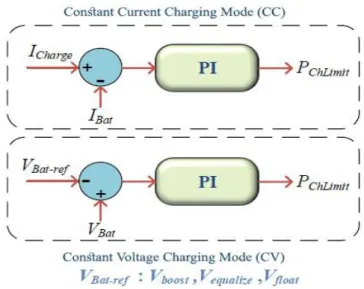
output power. In situation 3, which controls the PV voltage of the dc link, the task of the battery converter is to control the battery charge in the charge limitation state. In this case the battery should be charged at the maximum possible power. There are several ways to optimally charge batteries, the most common being two-stage charging with constant current and constant voltage (webpage). In this way, the battery is first charged by a constant current (I
charge) depending on the capacity and characteristics of the battery. Charging the
battery increases its voltage continuously until the voltage reaches the maximum value specified by the manufacturer (V boost). At this time, the battery
voltage reference is kept constant and as a result the battery charge current decreases gradually. When the battery is fully charged, the charging current drops to zero, and the battery voltage reference is reduced to the nominal value of the battery voltage (V float) which is specified by the manufacturer and it less
than (V boost) is specified. However, at the first charge of some types of battery,
the voltage applied to the battery is more than the (V boost) which is called (V equalize).
The method of controlling the battery adapter converter in different situations is shown in Fig. (2-10) the method of determining the coefficients of the controllers is described in [48].
Figure 2.9: Battery boost converter control methods in different situations As will be explained in the 2,3-mode description, the battery is also in the charge limit, but its charge is indirectly applied by adjusting the unit's output power.
In this case, the battery controls the voltage of the dc Link voltage, and for the battery to be charged at constant voltage or constant current, it is necessary to allow the battery charge to be set and the reference value of the output power equal to the PV power difference and the battery charge. The method for determining the battery charge power in each of the constant current and constant voltage modes is shown in Fig. (2-11). In this figure, 𝑃𝑐ℎ𝐿𝑖𝑚𝑖𝑡 < 0 is the battery power allowed.
Figure 2.10: Method for determining the Battery Authorized Charging Power in situation 2,3.
2.3.3 Inverter control
As shown in the block diagram block (2-6), the inverter control of each unit consists of the following sections:
2.3.3.1 Active and reactive power output calculation
One of the methods of calculating the actual and reactive power in a single -phase system is to calculate the power by the following equations using the perpendicular voltage and current components.
𝑃𝑜𝑢𝑡−𝑡 =1
2(𝑉𝛼𝐼𝛼+ 𝑉𝛽𝐼𝛽)
(2-2)
𝑄𝑜𝑢𝑡−𝑡 =1
2(𝑉𝛽𝐼𝛼− 𝑉𝛼𝐼𝛽)
In these equations, 𝑉𝛼 𝑎𝑛𝑑 𝐼𝛼 are Simultaneous phase values with output voltage and current, and 𝑉𝛽 𝑎𝑛𝑑 𝐼𝛽 are instantaneous values that are 90 degrees with
phase voltage and output difference. 𝑉𝑜𝑢𝑡−𝑡 𝑎𝑛𝑑 𝑄𝑜𝑢𝑡−𝑡 are the Instantaneous
values of active and reactive power. Given a sinusoidal component with twice the original frequency at the instantaneous power calculated by (2 -3), a low pass filter is used as below to calculate the average power.
𝑃𝑜𝑢𝑡 = 𝜔𝑓
𝑆+𝜔𝑓𝑃𝑜𝑢𝑡−𝑡 (2-3) 𝑄𝑜𝑢𝑡 = 𝜔𝑓
𝑠 + 𝜔𝑓𝑄𝑜𝑢𝑡−𝑡
There are various methods for generating a 90-degree phase difference signal compared to the original signal, which uses the SOGI (second order generalized integrator) method in this thesis. The block diagram of this method is shown in (2-12).
Figure 2.11: OSG perpendicular signal generation by SOGI-OSG method The most important feature of this method is that by adjusting its coefficients, the main harmonics and the signal perpendicular to the main harmonics can be extracted, therefore, even for nonlinear loads and high-disturbance loads, one can only calculate the actual and reactive power of the main component of voltage and current.
2.3.3.2 Active and reactive power control
In order to determine the frequency and amplitude of the inverter output voltage, a method based on the Droop method is used. In this method, the output voltage reference range is determined based on the Q-E common drop relation, but the output voltage reference frequency is determined by a new method based on the modified P-f droop relation, which will be described in detail below. 2.3.3.3 Virtual impedance
This section can add a self-resisting virtual impedance to the inverter output. The virtual impedance resistor is used to increase the stability of the droop method and its inductor to increase the X/R ratio of the inverter output [58]. In Section 2-3-9, the effect of the inverter output impedance and impedance on the droop method is investigated.
To implement the virtual impedance, the corresponding voltage dro op can be subtracted from the reference voltage value.
𝑉𝑣𝑖𝑟 = 𝑅𝑣𝐼𝑜𝑢𝑡+ 𝐿𝑣𝑑𝐼𝑜𝑢𝑡
Assuming the output current is sinusoidal, its derivative has a 90 -degree difference from its original value, so the 𝐼𝛽 value can be used to prevent the implementation of the virtual inductor to prevent the derivative from being implemented.
𝑉𝑣𝑖𝑟 = 𝑅𝑣𝐼𝑜𝑢𝑡− 𝐿𝑣𝜔𝐼𝛽 (2-5) It should be noted that in this respect, the virtual predecessor exists only at the original frequency. To implement the virtual inductor in other harmonics, the perpendicular component of the current in the desired harmonics can be used, which can be easily extracted by SOGI method.
2.3.3.4 Voltage control
By this section, it follows the output voltage reference voltage determined by the active and reactive power control section from which the virtual impedance voltage is lowered. To increase speed and improve control loop stability, the double-loop control voltage is used as an (2-13) shape.
Figure 2.12: Inverter output voltage control loop
This control system consists of an external voltage control loop, Gv(s), and an internal current control loop, GI(s). For voltage and current control loops, linear controllers such as proportional-integral (PI) and proportional-resonant (PR) controllers are widely used because of their simple design and implementation. Due to the inability of the controller (PI) to follow the sinusoidal reference and the steady state error in amplitude and phase, most of the (PR) controllers are used.
The general structure of a (PR) controller is as follows: 𝐺𝑐(𝑠) = 𝐾𝑝+ 𝐾𝑖 𝜔𝑐𝑠
𝑠2+2𝜔
𝑐+𝜔2 (2-6) Where 𝐾𝑝 , 𝐾𝑖 and 𝜔 are proportional gain, integral gain, and controller resonance frequency, and 𝜔𝑐 is the frequency of the controller cutoff, which
reduces the sensitivity of the controller gain to the voltage reference frequency change. Compensation of different harmonics is possible through the combination of multiple proportional-resonance controllers. For this purpose, the compensator conversion function is considered as follows (PR+H):
𝐺𝑐(𝑠) = 𝐾𝑝+ 𝐾𝑖 𝜔𝑐𝑠 𝑠2+2𝜔 𝑐𝑠+𝜔2+ ∑ℎ−3,5,7…𝐾𝑖ℎ 𝜔𝑐ℎ𝑠 𝑠2+2𝜔 𝑐ℎ𝑠+(ℎ𝜔)2 (2-7) The conversion of this function as a chart is shown in Figure (2 -14).
Figure 2.13: The graph chart of 𝐺𝑐(𝑠) with harmonic offsets of 3,5 and 7.
In the figure (2-14) a compensator (PR+H) is used for both voltage and current control loops. To determine the coefficients of the drives, the closed loop control diagram of the system is considered as (2-15), [59]. Since in closed-loop control, the capacitor voltage and the current of the inverter side of the inverter are controlled, the output filter type can be considered a filter (LC) with an output inductor of (L0).
Using Mason's theory, the closed-loop voltage control function of the capacitor is written as follows: 𝑉𝑐(𝑠) = 𝐺𝑉𝑟𝑒𝑓. 𝑉𝑟𝑒𝑓− 𝑍𝑜𝑢𝑡𝐼𝑜𝑢𝑡 = 𝐺𝑉(𝑠)𝐺𝐼(𝑠)𝐺𝑃𝑊𝑀(𝑠) 𝐿𝐶𝑠2+𝑟𝐶𝑠+(𝐶𝑠+𝐺 𝑉(𝑠))𝐺𝐼(𝑠)𝐺𝑃𝑊𝑀(𝑠)+1𝑉𝑟𝑒𝑓(𝑠) − 𝑟+𝐿𝑠+𝐺𝐼(𝑠)𝐺𝑃𝑊𝑀(𝑠) 𝐿𝐶𝑠2+𝑟𝐶𝑠+(𝐶𝑠+𝐺 𝑣(𝑠))𝐺𝐼(𝑠)𝐺𝑃𝑊𝑀(𝑠)+1𝐼𝑜𝑢𝑡(𝑠) (2-8) Which 𝐺𝑃𝑊𝑀(𝑠) = 1 1+1.5𝑇𝑠.𝑠 (2-9) Is the Inverter conversion function, 𝑇𝑠 is the Inverter sampling frequency and 𝑟 is the resistive inductor of (Lf) filter The method of adjusting the coefficients of voltage and current compensators is fully described in [60]. Assuming the specification of table (2-4) and the compensation coefficients 𝐾𝑃𝐼 = 5.6, 𝐾𝑖𝐼 = 300, 𝐾𝑖3,5,7,9𝐼 = 30, 𝐾𝑝𝑉 = 0.05, 𝐾𝑖𝑉 = 100, 𝐾𝑖3,5,7,9𝑣= 50 of the diagram were the
conversion function 𝐺𝑉𝑟𝑒𝑓 = 𝑉𝑐(𝑠)
𝑉𝑟𝑒𝑓(𝑠)
⁄ shown in Figure (2-16). As can be seen, the gain is the closed-loop conversion function of the desired frequencies 1 and its phase 0 indicating that the controller can follow the voltage reference exactly.
Figure 2.15: table chart of the closed loop conversion function of 𝐺𝑉𝑟𝑒𝑓 = 𝑉𝑐(𝑠)
𝑉𝑟𝑒𝑓(𝑠)
The output impedance of the system, which is the output voltage for the perturbation current, is also shown in Fig 2-17. The small impedance at the desired frequency affects the effect of the output current reduces voltage control.
Figure 2.16: System output impedance in the frequency domain 2.3.3.5 An overview of droop method
The Droop method is one of the most common methods for dividing the active and reactive power between distributed generation units by decentralized method. To illustrate the Droop method, consider a few scattered inverter generating units connected to a common bus. Each unit can be modeled as an ideal series impedance voltage source as shown below.
Figure 2.17: The equivalent circuit of a distributed generation unit connected to a common bus
In this equivalent circuit, 𝐸 < 𝜑 is the inverter open circuit voltage, 𝑉 > 0 common bus voltage, 𝑍 < 𝜃 impedance between the inverter and the common bus (sum of inverter output impedance and line impedance), and 𝑆 = 𝑃 + 𝑗𝑄 is the inverter output power. According to this circuit the inv erter output current is as follows: 𝐼 =𝐸<∅−𝑉<0 𝑍<𝜃 = 𝐸 𝑍< (𝜙 − 𝜃) − 𝑉 𝑍 < (−𝜃) (2-10)
As a result, the actual and reactive power output of the inverter injected into the shared bus is calculated as follows:
𝑃 =𝑉
𝑍[(Ecos ∅ − 𝑉) cos 𝜃 + Esin ∅ sin 𝜃] (2-11)
𝑄 =𝑉
𝑍[(Ecos ∅ − 𝑉) sin 𝜃 + Esin ∅ cos 𝜃]
If the impedance Z is a self-propelled Z (Z=X<90), given that φ is a small value, then the (2 - 11) equation is simplified as follows:
𝑃 =𝐸𝑉 𝑋 sin 𝜙 ≈ 𝐸𝑉 𝑋 𝜙 (2-12) 𝑄 =𝐸𝑉 cos 𝜙−𝑉2 𝑋 ≈ 𝑉 𝑋(𝐸 − 𝑉)
This relationship shows that with the above assumptions, the real power is more dependent on the phase difference between the inverter voltage and the shared bus and reactive power are more dependent on the voltage range. Therefore, it is possible to control the actual output power of the inverter output voltage phase and control the reactive power output of the inverter output voltage range. Since the phase is a frequency integral, the voltage phase can be indirectly changed by changing its frequency.
In the Droop method, the reference frequency and amplitude of the output voltage of each unit are determined as follows:
𝑓 = 𝑓𝑛− 𝑚𝑝𝑃 (2-13) 𝐸 = 𝐸𝑛 − 𝑚𝑞𝑄
Where 𝑓𝑛 and 𝐸𝑛 are the load frequency and rated voltage output voltage.
𝑚𝑝 and 𝑚𝑞 , called droop coefficients, are determined by the inverse of the power capacity of each unit.
𝑚𝑝 = Δ𝜔𝑚𝑎𝑥 𝑃𝑚𝑎𝑥 (2-14) 𝑚𝑞= Δ𝐸𝑚𝑎𝑥 𝑄𝑚𝑎𝑥
By the above method, assuming that 𝑓𝑛 and 𝐸𝑛 are the same in all units, in steady state the following relation exists between the output power of the units: 𝑚𝑝1𝑃1 = 𝑚𝑝2𝑃2 = ⋯
𝑚𝑞1𝑄1 = 𝑚𝑞2𝑄2 = ⋯ (2-15)
𝑃1 + 𝑃2+ ⋯ = 𝑃𝐿𝑜𝑎𝑑
𝑄1+ 𝑄2+ ⋯ = 𝑄𝐿𝑜𝑎𝑑
As a result, the output power of each unit is proportional to its capacity. Assuming the units are the same, the output power of the units will be the same and the load power will be distributed equally between the units. It should be noted that due to the use of a low pass filter in the output power calculation, the droop control bandwidth is much less than the voltage control loop bandwidth and it can be assumed that the voltage control loop can quickly follow the voltage reference specified by the droop control.
2.3.4 General modes of micro-grid performance in the proposed method
In different load conditions, the maximum available PV power and the charge capacity of the micro-grid batteries, the grid can operate in three general modes. In the next section, the performance status of each microcontroller unit is divided into six states, each of which (with the exception of t he intermediate state 2,3 which may correspond to the second or third state) corresponds to one of the general states of the microcontroller operation.
It should be noted that, as will be explained, the positioning of the Micro -grid units is decentralized and based solely on local measurements and does not require the information of other Micro-grid units and the amount of Micro-grid load. it also determines the state of the network. Given that the aim of the proposed power management approach is Active power management, reactive power is divided by the common Q-E drop method (Relation (2-13)).
To execute decentralized real power management, the following droop general function is used, which is a modified form of the common droop method:
𝑓 = 𝑓𝑛+ (𝑚𝑝+ 𝑚𝑖
𝑠) (𝑃𝑟𝑒𝑓− 𝑃𝑜𝑢𝑡) (2-16)
Depending on the mode of operation, the coefficients 𝑚𝑝, 𝑚𝑖 and 𝑓𝑛 and 𝑃𝑟𝑒𝑓 are determined, where 𝑓𝑛 is the reference frequency.
State 1:
In this case, the micro-grid load power is greater than the total micro-grid PV power and the batteries provide overload:
𝑃𝐿𝑜𝑎𝑑 > ∑ 𝑃𝑃𝑉−𝑀𝑃𝑖
𝑚
𝑖=1 (2-17)
In this respect 𝑃𝑃𝑉−𝑀𝑃 is the maximum PV power of unit 𝑖 depending on the
environmental conditions and the amount of sunlight. Three methods can be used to split the overload between batteries:
In the first method, the power load is divided between units according to the common Droop method1 The values of the relationship coefficients (16-2) for this method are:
𝑓𝑛 = 𝑓0, 𝑚𝑝 = ∆𝑓𝑚𝑎𝑥
𝑃𝑜𝑢𝑡−𝑚𝑎𝑥, 𝑚𝑖 = 0, 𝑃𝑟𝑒𝑓 = 0 (2-18) Where 𝑃𝑜𝑢𝑡−𝑚𝑎𝑥is the maximum capacity of the unit inverter and 𝑓0 is the nominal frequency of the micro-grid. In this method, regardless of 𝑃𝑃𝑉−𝑀𝑃 units,
the power is divided solely based on the inverter capacity of the units. The advantage of this method is the balanced distribution of power losses between units, but this method requires the reduction of 𝑃𝑉 power in units with larger 𝑃𝑉 power. As a result, maximum 𝑃𝑉 power is not used.
In the second method, the 𝑃𝑉 incremental converter of all units is controlled so that all solar arrays are produced at their maximum power point 𝑃𝑃𝑉 = 𝑃𝑃𝑉−𝑀𝑃). Charging power is divided between units so that the total discharge capacity of the battery needed to supply the overload is divided by capacity and SoC of the batteries.
The values of the relation (2-16) coefficients for this method are: 𝑓𝑛 = 𝑓0, 𝑚𝑝 = 𝑚𝑝𝑑0 1
𝑆𝑜𝐶, 𝑚𝑖 = 0, 𝑃𝑟𝑒𝑓 = 𝑃𝑃𝑉 (2-19)
Where 𝑚𝑝𝑑0 is a constant coefficient that is chosen in proportion to the capacity of the battery or unit capacity, ie, the battery that has the greater capacity, the 𝑚𝑝𝑑0 is chosen less to allow greater discharge. This coefficient is also chosen
so that the system is stable within the permissible 𝑆𝑜𝐶 range of each unit and 𝑛 determines the 𝑆𝑜𝐶 balancing rate [61].
By 𝑀𝑃𝑃𝑇, method the 𝑃𝑉 power is controlled at the maximum power point and the battery per unit maintains the power balance at the 𝑑𝑐 link, in other words, it provides the difference between the inverter output power and the 𝑃𝑉 power. Regardless of casualties, the battery charge per unit is as follows:
𝑃𝐵𝑎𝑡 = 𝑃𝑜𝑢𝑡− 𝑃𝑃𝑉 (2-20)
Therefore (2 - 16) is written as follows:
𝑓 = 𝑓0− 𝑚𝑝𝑃𝐵𝑎𝑡 (2-21) This relationship, which is similar to the current Droop relationship, results to the division of battery capacity between the units based on their capacity and 𝑆𝑜𝐶, so that the unit that has more 𝑆𝑜𝐶 and capacity, will have more discharge capacity, in order that all batteries will eventually have the same 𝑆𝑜𝐶. In this case, the discharge capacity of the batteries will be proportional to their capacity. It should be noted that the battery power is consid ered positive in the discharge state and negative in the charge state.
In the third method, depending on the capacity and 𝑆𝑜𝐶 of the battery, the residual capacity of the inverter when the 𝑃𝑉 is operating at the maximum power point 𝑀𝑃𝑃𝑇, also plays a part in the load power distribution. In this way, if the capacity and 𝑆𝑜𝐶 of the batteries are the same, the unit with maximum inverter capacity and 𝑃𝑃𝑉−𝑀𝑃 will have higher output power. The values of the relationship coefficients (16-2) for this method are:
𝑓𝑛 = 𝑓0, 𝑚𝑝 = 𝑚𝑝𝑑0 1
𝑆𝑜𝐶×
𝑃𝑜𝑢𝑡−𝑚𝑎𝑥
𝑃𝑜𝑢𝑡−𝑚𝑎𝑥−𝑃𝑃𝑉−𝑀𝑃 , 𝑚𝑖 = 0, 𝑃𝑟𝑒𝑓 = 𝑃𝑃𝑉−𝑀𝑃 (2-22) In this method, on the first method all units work at maximum power point and the output power of the units is more balanced than on the second method.
![Figure 2.4: The micro-grid studied in [49].](https://thumb-eu.123doks.com/thumbv2/9libnet/4174399.64411/27.892.209.742.235.452/figure-the-micro-grid-studied-in.webp)