Detailed Analysis of DC Choppers and An Example of PMDC Motor Speed Control
MUHAMMED REŞİT ÇORAPSIZ 1, BÜNYAMİN ALIM 1 and HAKAN KAHVECİ 21Vocational School of Technical Science, Department of Electricity and Energy, Bayburt University, TR-69000, Bayburt, Turkey 2Faculty of Engineering, Department of Electric and Electronic Engineering, Karadeniz Technical University, TR-61080,
Trabzon, Turkey Abstract
DC-DC converters have recently been started to be used frequently in power electronics applications in parallel with the development of semiconductor technology. It is possible to encounter frequently to these converters, which are basically divided into two groups as DC choppers and switching regulators, in transport vehicles, chargers and physically small electronic devices. Also, choppers are one of the effective methods used to control of DC motor. In this paper, a detailed analysis of DC choppers, a type of DC-DC converters, has been performed. Firstly, DC choppers operating in the 1st, 2nd, 3rd and 4th quadrants have been designed separately. Secondly, a converter model operating in both the 1st quadrant and the 3nd quadrant has been designed by combining the 1st and 3rd quadrant converters due to the fact that two-quadrants or four-quadrants control can be performed by combining the quadrants. Finally, all of the simulation models have been designed in the Matlab/SIMULINK environment and the current and voltage components of the converters have been measured. Furthermore, an example of DC motor speed control with a chopper having one quadrant have been given as an example to the application areas of the choppers. Consequently, it has been observed that the performance of the chopper fed control techniques is also quite high compared with the DC motor control techniques in the literature.
Keywords: DC Chopper, PMDC Motor Control, Armature Voltage Control, Pulse Width Modulation (PWM), MATLAB/Simulink.
Received: 20.04.2018 Revised: 15.05.2018 Accepted:21.05.2018
Corresponding author: Muhammed Reşit ÇORAPSIZ, PhD Vocational School of Technical Science, Department of Electricity and Energy, Bayburt University, Bayburt, Turkey
E-mail: [email protected]
Cite this article as: M. R. Çorapsız, B. Alım, and H. Kahveci, Detailed Analysis of DC Choppers and An Example of PMDC Motor Speed Control, Eastern Anatolian Journal of Science, Vol. 4, Issue 1, 16-36,2018.
1. Introduction
In many industrial applications, different voltage levels are needed using existing DC voltage sources. Existing sources such as solar cell, batteries and accumulators are used to convert different types of energy into electricity energy. However, when these sources are used to generate DC voltage, a constant-amplitude voltage is obtained at the output. Although it is possible to produce power supplies that can be used for different voltage levels, this situation will cause in both cost increases and the need for physically larger resources. Therefore, using an intermediate circuit that can provide energy transfer to produce a DC voltage at a desired amplitude from a constant DC voltage will eliminate these problems. As is known, this process is done with a transformer at AC voltages.
Transformers provide power transfer by changing the amplitude of only the current and voltage components of the AC source that is fed under constant power and frequency. This process at DC voltage is done by choppers. The operating principle of the choppers is based on switching the DC input voltage on the load, and control of the switching is usually done by pulse width modulation (PWM) which is known as the easiest control method (BODUR, 2012). A Chopper is considered as a DC equivalent of an AC transformer as they behave in an identical manner (NAGARAJAN et al., 2017). The adjustable DC sources are used in order to fed electric motors in applications such as fast transport, electric trains, electric vehicles, electric cranes. DC-DC choppers are used to obtain an adjustable DC voltage having an average voltage value from a DC source with a constant voltage (BAL, 2008). They are also used in regenerative breaking of DC motors to return energy back to supply and also as DC voltage regulators. With these features, they save energy in a transport
EAJS, Vol. IV, Issue I Detailed Analysis of DC Choppers and An Example of PMDC Motor Speed Control | 17
system having frequent stopping places (RASHID, 2015). Additionally, DC choppers have the advantages such as high efficiency, fast dynamic response, low maintenance, small dimensions and easy control.
The process of transferring to the output by step-down or step-up the level of DC voltage that the choppers receive from the input depends on both the position in the circuit and the duty cycle of a controlled semiconductor switch in the structure of the choppers. The duty cycle can be defined as the ratio of the time that the semiconductor switch is in conduction to the time for an electrical period. The desired output current and voltage values are obtained by controlling these semiconductor switches in the required shapes. These semiconductor switches may be bipolar junction transistor (BJT), metal oxide semiconductor field effect power transistor (MOSFET), gate turn off transistor (GTO) or insulated gate bipolar transistor (IGBT) (RASHID, 2015). Moreover, the rapid development of semiconductor technology, especially over the past two decades, has pioneered significant innovations in the control of AC and DC motor drive systems by allowing the production of power switching elements having physically smaller dimensions and faster dynamic response (ALTUN et al., 2008).
In the present paper, firstly, circuit structures of DC choppers during the first, second, third and fourth quadrants operation were analyzed. Secondly, the changes of the input currents, load currents and load
voltages occurring in the circuit structures has been investigated by performing simulations of the quadrants separately via the theoretical information obtained from this analysis. Finally, DC motor control with a DC chopper operating in the first quadrant has been performed in order to show an example to application areas. The rotor speed, the armature current and the torque values produced of the supervised chopper fed DC motor have been measured. Consequently, the applicability of the proposed control method has been evaluated in detail by the obtained data.
2. Analysis of DC Choppers
Before examining the operating states of DC-DC choppers, it is must to know how the semiconductor switches used in these converters obtain the trigger signals they need to perform the desired duty.
2.1. Producing of a Signal Having Desired Occupancy Rate
These signals are usually created by comparing a reference signal with a carrier signal by a comparator. Thus, a signal having desired occupancy rate can be produced. Semiconductor switches remain in conduction for a period of time defined as the duty ratio, the duty cycle or the occupancy rate. The duty cycle is determined by ratio of the time between the rising edge of the generated signals and the falling edge of the generated signals to the time elapsed in a period of the signal.
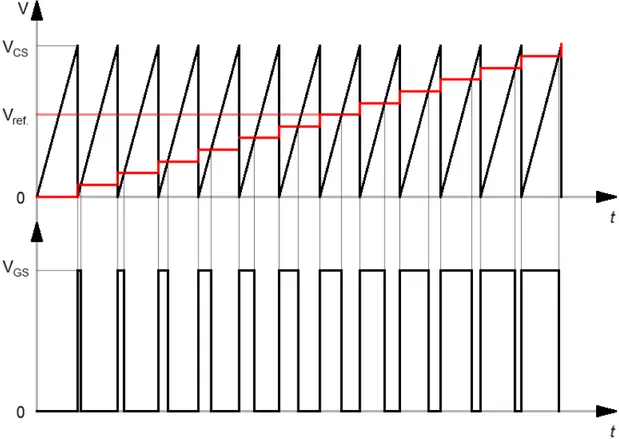
Fig. 1. Producing of a signal having desired occupancy rate.
The generated signal (VGS) which is have the desired occupancy rate and are created by comparing the carrier signal (VCS) with the reference signal (Vref.) is shown in Fig. 1. Where VCS and Vref are represent the peak values of signal and obtained from the following equation:
V
r feV
CSt
T
(1) At the end of the duty cycle, VCS value equals Vref value. Therefore, Eq. (1) can be written as in Eq. (2).
V
r feV
CSkT
T
(2)Where k is the duty cycle and the k value can be expressed as in Eq. (3) with the comparison of the two signals (RASHID, 2015).
r fe CS
V
k
V
(3)As seen from Eq. (3), the duty cycle is determined by the ratio of the reference signal to the carrier signal. This ratio can be set to desired value between 0 and 1.
If the reference signal is greater than the carrier signal, the desired signal is created by pulling the generated signal to a positive value. In the opposite case, the desired signal is created by pulling the generated signal to zero value. Thus, gate signals for semiconductor switches are generated. It can be seen from Fig. 1 that the occupancy ratio also increases linearly with increasing the amplitude of the reference signal. If it is wanted that the signal having desired occupancy rate is to be produced at constant frequency with a constant duty cycle for each electrical period, the reference signal must be a constant value between 0 and VCS.
2.2. Operating Principle of DC Choppers
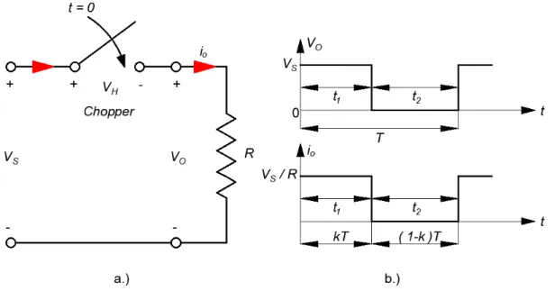
The chopper circuits are obtained with connecting a semiconductor switch to the serial path of the input current of the circuit. Thus, the desired output voltage can be adjusted by changing the duty ratio of the semiconductor switch. A step-down DC chopper circuit is shown in Fig. 2 for a clearer understanding of the operating principle of DC choppers.
EAJS, Vol. IV, Issue I Detailed Analysis of DC Choppers and An Example of PMDC Motor Speed Control | 19
Fig. 2. Step-down operation a.) Electrical circuit b.) Voltage and current waveforms. As can be seen in Fig. 2(a), when the semiconductor
switch which is defined as chopper is ON (meaning conducting) at t=0, the source voltage at the input is applied to the load during t1 time. There is usually occur a voltage drop (VH) of between 0.3-2V on such switches used in practice. However, this VH value is neglected in most theoretical calculations in terms of ease of calculation. In this case, when the VH value on the switch is neglected, the all of the input voltage will be visible on the load because of the fact that the load will be connected parallel to the source. When the switch is OFF (meaning not conducting) at the end of t1 time, the load voltage is zero during the t2 time due to the fact that it is not connected to any source and there is no current flow on the load. Thus, the duty cycle of the switch can be found by proportioning the duration of the conduction to the duration of an electrical period.
The ON and OFF situations of the switch are shown in Fig. 2(b). In this case, the duty cycle can be found in Eq. (4). 1 1 1 2
t
t
k
t
t
T
(4)So that the average output voltage is given as in Eq. (5). 1 1 1 0
1
t o s s s st
V
V dt
V
ft V
kV
T
T
(5)Where Vs is input voltage, Vo is the average value of the output voltage, T is the chopping period, k is the duty cycle of chopper and f is the frequency of chopper. The effective resistance value seeing by the source can be calculated from the following equation.
/
s s i o sV
V
R
R
i
kV
R
k
(6)Where io is the average value of the load current. According to Eq. (6), the load resistance (R) is converted by the converter into a variable resistance R/k. This situation explains how changes of the voltage value on the load with changes of the value of k which is defined as duty ratio of the switch. The duty ratio is set to a value between 0 and 1 by changing the switching parameters t1 and T or f. Thus, the power flow is controlled by setting to a value between 0 and Vs the output voltage value (RASHID, 2015).
2.3. Operating Quadrants of DC Choppers
The DC choppers are separated to operating quadrants with respect to the voltage on the load they feed and the polarity of the current flowing through the load. In these quadrants, the polarity of the load voltage and the polarity of the load current may be the same direction or opposite direction to each other. For example, while the voltage and current of the load fed
by a DC chopper operating in the first quadrant is in the positive direction, the load voltage fed by a DC chopper operating in the second quadrant is still in the
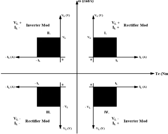
positive direction and the load current is in the negative direction. This situation is shown separately for 4-quadrants in Fig. 3.
Fig. 3. The operating quadrants, current and voltage polarities of DC choppers. As the DC motor example was given in the present
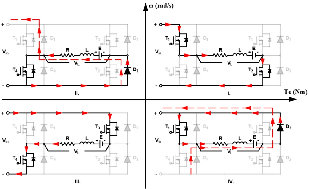
paper, it would be useful to explain the operating quadrants from a DC motor. In Fig. 3, the quadrants marked with roman numerals is the operating quadrants of DC chopper, VL is the load voltage, IL is the load current, ω is the rotor speed, Te is the torque generated by the motor. The operating quadrants of the DC chopper are shown via an H-bridge converter in Fig. 4. H-H-bridge converters are used for DC motor control and also can run the motor in all 4-quadrants of speed-torque plane (DAS, SWAIN, 2017). In the present study, MOSFET was used as a semiconductor switch in the H-bridge converter. Freewheeling diodes were connected in anti-parallel to these switches in order to both to protect of semiconducting switches from reverse current situation and to use the energy stored on the load for different purposes in inductive loads. Among these purposes, it can also be shown that DC motors
transfer their energy to the source by regenerative braking. The load specified as R - L in Fig. 4 represents a DC motor. The DC motors produce back EMF voltages depending on the magnitude of the speed during rotation. This back EMF voltage produced is given in Eq. (7) (E = Eb).
E
b
k
m
(7) Where Eb is the back EMF voltage produced, km is the back EMF coefficient, ϕ is the magnetic field generated by permanent magnets and ω is the rotor speed in rad/s. When Fig. 3 and Fig. 4 are examined together, the operating quadrants of the 4-quadrant chopper can be summarized as follows provided that VL is the converter output voltage or load voltage.EAJS, Vol. IV, Issue I Detailed Analysis of DC Choppers and An Example of PMDC Motor Speed Control | 21
(i) Quadrant 1: In the first quadrant, T1 and T2 switches are continuously ON, T3 and T4 switches are continuously OFF. Namely, T1 and T2 switches are conducting this mode. As can be seen from 1st quadrant in Fig. 4, the current shown by the flow arrows is correct from the source to the load. This situation is also known as motor operate in the forward direction. If the T1 switch is OFF and the T2 switch is ON, the load current begins to decrease through T2 switch and D4 diode. Therefore, as can be seen from 1st quadrant in Fig. 3, there are the inequalities VL > Eb and IL > 0 in this quadrant.
(ii) Quadrant 2: In the second quadrant, T1, T2 and T3 switches are OFF. When the T4 switch is ON, the load current begins to flow by increasing through T4 switch and D2 diode. As can be seen from 2nd quadrant in Fig. 4, When the T4 switch is OFF, the energy accumulated on the inductive load is transferred to source through D1 and D2 diodes. Namely, the power flows from load to source. This quadrant is also called as generator operate in the forward direction or recovery in the forward direction. As can be seen from 2nd quadrant in Fig. 3, there are the inequalities VL < Eb and IL < 0 in this quadrant.
(iii) Quadrant 3: In the third quadrant, T3 and T4 switches are continuously ON, T1 and T2 switches are continuously OFF. Namely, T3 and T4 switches are conducting this mode. As can be seen from 3rd quadrant in Fig. 4, the current shown by the flow arrows is correct from the source to the load. This situation is also known as motor operate in the opposite direction. If the T3 switch is OFF and the T4 switch is ON, the load current begins to decrease through T4 switch and D2 diode. Hence, as can be seen from 3rd quadrant in Fig. 3, there are the inequalities |VL| > |Eb| and IL < 0 in this quadrant.
(iv) Quadrant 4: In the fourth quadrant, T2, T3 and T4 switches are OFF. When the T1 switch is ON, the load current begins to flow by increasing through T1 switch and D3 diode. As can be seen from 4th quadrant in Fig. 4,
when the T1 switch is OFF, the energy accumulated on the inductive load is transferred to source through D3 and D4 diodes. Namely, the power flows from load to source. This quadrant is also called as generator operate in the opposite direction or recovery in the opposite direction. As can be seen from 4th quadrant in Fig. 3, there are the inequalities |VL| < |Eb| and IL > 0 in this quadrant.
3. The Model of PMDC Motor
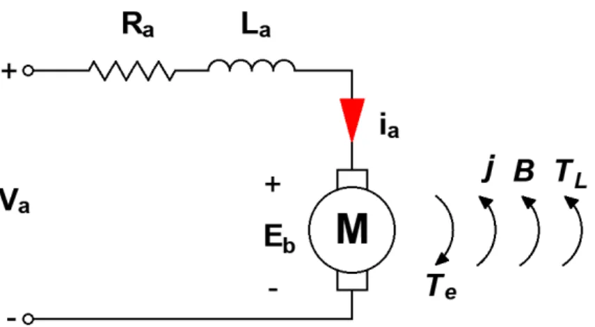
Permanent magnet DC motors are used in many application areas due to the fact that they have advantages such as simple construction and easy control. DC motors have a long tradition of being used as adjustable speed machines and a wide range of options have evolved for this purpose (NAGARAJAN et al., 2016). These motors have stationary and moving parts in their structure. While the permanent magnets are placed on the stationary stator, the armature windings are placed on the moving rotor. DC motors are used in adjustable speed and precise positioning applications such as fast transport, electric trains, electric vehicles, electric winches, printer, floppy drive, paper industry (ÇOLAK et al., 2007). Therefore, a lot of scientific works has been done for DC motors and many control methods have been developed. DC motors have come to the forefront due to above mentioned features. However, DC motors have some disadvantages because they have a limited amount of load and need a lot of maintenance (ÇORAPSIZ, KAHVECİ, 2017). The DC motor equivalent circuit obtained from the dynamic equations is shown in Fig. 5. In this figure, where Ra is the armature winding resistance, La is the armature winding inductance, Va is the motor input voltage, ia is the armature current, Eb is the back EMF induced in the reverse direction to the input voltage, Te is the produced torque, j is the inertia moment, B is the friction coefficient and TL is the load torque. Because the magnetic field in permanent magnet DC motors is directly generated by permanent magnets placed in the stator, the relationship between the generated moment and the armature current can be expressed as in Eq. (8).
EAJS, Vol. IV, Issue I Detailed Analysis of DC Choppers and An Example of PMDC Motor Speed Control | 23
Fig. 5. The model of Permanent Magnet DC Motor
T
e
k
m
i
a (8) When KVL is applied to the circuit in Fig. 4, the Eq. (9) given below is obtained.
V
aR i
a aL
adi
aE
bdt
(9)When the change of armature current is assumed to be zero in the steady state and equations (7) and (8) are substituted in Eq. (9), the motor speed is obtained as in Eq. (10).
2 a a e m mV
R T
k
k
(10) As can be seen from Eq. (10), the speed of a permanent magnet DC motor can be controlled by changing either the input voltage or the resistance of the armature because of the fact that km and ϕ are constant. It is clearly seen that the armature resistance should be increased to reduce the rotor speed in the control carried out with armature resistance change. This situation is not preferred due to the increase in losses (ALTUN et al., 2008). Traditionally rheostatic armature control method was widely used for the speed control of low power dc motors. However, thecontrollability, cheapness, higher efficiency, and higher current carrying capabilities of static power converters brought a major change in the performance of electrical drives (GEORGE, 2008). Therefore, it can be said that armature voltage control is one of the most effective control methods for permanent magnet DC motors.
3.1. DC Motor Speed Control with One-Quadrant Chopper
The quite different control methods have been developed for DC motors, parallel to the use of DC motors in many application areas of the industry. Especially, PI and PID controllers have become traditional in the control of these motors. The disadvantages of using conventional controllers are that they are sensitive to variation in the motor parameters and load disturbance. In addition, it is difficult to tune PI or PID gains to eliminate and reduce the overshoot and load disturbance (PRAKASH, VASANTHI, 2013).
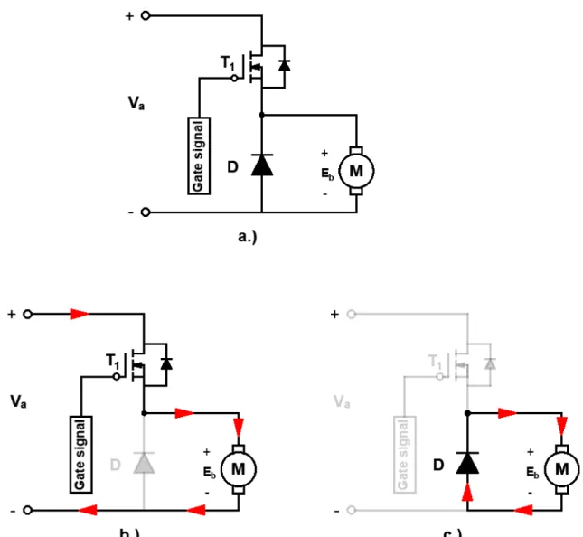
Fig. 6.
The control of armature voltage with one-quadrant DC chopper a.) Electrical circuit b.) The motor
operation in the forward direction c.) The gap operation.
The circuit of the armature voltage control of DC motor with one-quadrant DC chopper is shown in Fig. 6. In this control method, the speed of the motor can be controlled via adjusting the armature voltage by changing the duty ratio of the semiconductor switch in the circuit as shown in Fig. 1 (BAL, 2008.). The speed of a DC motor can be controlled by varying the voltage applied to the terminal. These can be done by using a pulse width modulation (PWM) technique. A filed voltage signal with varying pulse-width is applied to the motor terminal (DEWANGAN et al., 2012). Thus, Vo representing the average value of the motor terminal voltage can be calculated as in following Eq. (11). 0
1
( )
T on o a a at
V
V t dt
V
kV
T
T
(11)In Fig. 6(b), when the T1 switch is ON, the source voltage is directly transferred to the motor terminal voltage. When the T1 switch is OFF in Fig. 6(c), the motor is disconnected from the source. This quadrant is defined as the void working region and the armature current flows by decreasing through the freewheeling diode connected in anti-parallel to the motor. Thus, the speed control is performed by adjusting the motor terminal voltage by the DC chopper. Hence, this control method is very common in the industry due to both its easy control and its simple applicability. In addition to, DC drives,
EAJS, Vol. IV, Issue I Detailed Analysis of DC Choppers and An Example of PMDC Motor Speed Control | 25
because of their simplicity, ease of application, reliability and favorable cost have long been a backbone of industrial applications and these drives are less complex as compared to AC drives system (ANASAARI, MEHTA, 2015).
4. Simulation Results
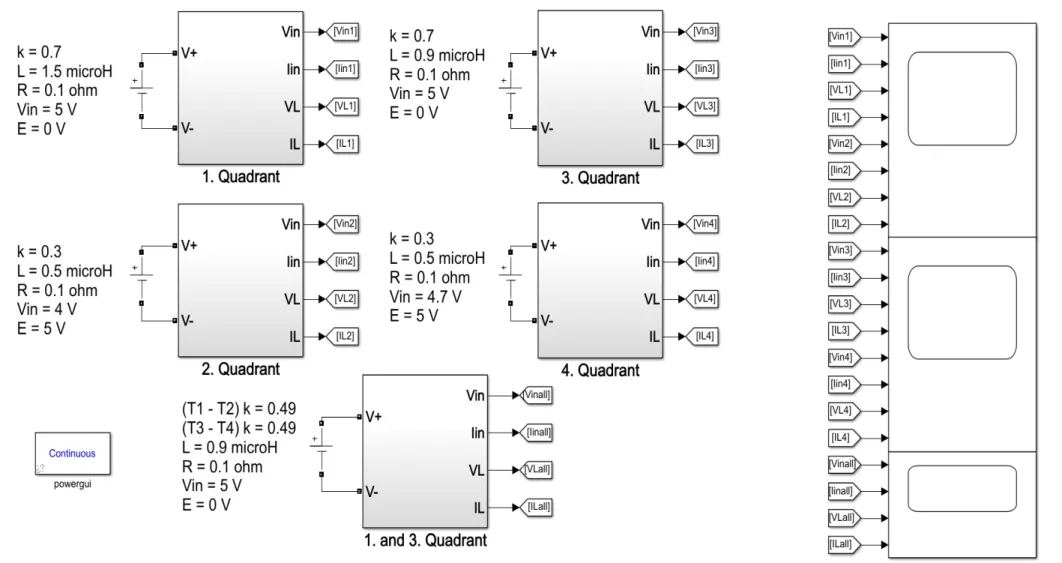
Fig. 7 shows the simulation models of first, second, third, fourth quadrants and the simulation model the first and third quadrants converters for two quadrants control. The symbols on the left side of the models are in respectively; k is the duty ratio of switch, L is the load inductance, R is the load resistance, Vin is the input voltage and E is the back EMF produced by the motor. Changes were made in k, L, Vin, E values in some quadrants in order to both taking into account conditions in the operating quadrant and obtain approximately the same values at the output magnitudes. The results obtained were compared by measuring load voltage (VL), load current (IL) and converter input current (Iin) in the simulation results. These results obtained is shown in Figs.8,9,10 and 11, respectively. The evaluation of these results by taking into consideration the current and voltage polarities of the load given in Fig. 3 is important in terms of the correctness of the operating quadrants.
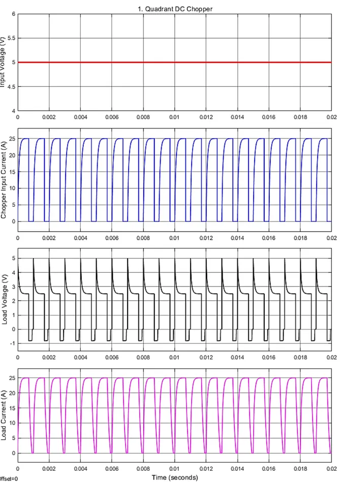
In Fig. 8, it is seen that the load voltage and the load current are positive when the results of the first quadrant converter have been considered. It can be said that the chopper in this quadrant is operating in rectifier mode. In Fig. 9, in the second quadrant converter, the load current is negative while the load voltage is again positive. The chopper in this quadrant is operating in inverting mode.
When the output magnitudes of the third quadrant converter in Fig. 10 have been examined, it is seen that both the load voltage and the load current are negative. The chopper in this quadrant is operating in rectifier mode as in first quadrant converter. In Fig. 11, in the fourth quadrant converter, the load current is positive while the load voltage is negative. The chopper in this quadrant is operating in inverting mode as in second quadrant converter.
The measured magnitudes of the two-quadrants (1 and 3) converter that occur with the combination of the first and third operating quadrants are shown in Fig. 12. The two-quadrants control of DC motor can be easily controlled via this converter. For a DC
motor controlled by this converter, while the forward direction motor work expression for the first quadrant converter is used, the opposite direction motor work expression for the third quadrant converter is used. The control of the DC motor with one-quadrant chopper has been performed in order to show that choppers are one of the most effective methods of DC motor control in terms of exemplifying the above mentioned information.
EAJS, Vol. IV, Issue I Detailed Analysis of DC Choppers and An Example of PMDC Motor Speed Control | 27
EAJS, Vol. IV, Issue I Detailed Analysis of DC Choppers and An Example of PMDC Motor Speed Control | 29
EAJS, Vol. IV, Issue I Detailed Analysis of DC Choppers and An Example of PMDC Motor Speed Control | 31
The simulation model of this control is shown in Fig. 13. The circuit parameters of the permanent magnet DC motor used in this simulation are given in Table 1. A reference speed magnitude has been applied to the DC motor in this simulation study and the speed error have been calculated by comparing this speed with the rotor speed. The PI controller generates the control signal necessary to eliminate this error. The generated control signal determines the gate signal for
the semiconductor switch in the chopper by comparing it with a triangular carrier signal as in Fig. 3. The chopper adjusts the speed of the motor in accordance with the given reference speed by increasing or decreasing of the armature voltage according to the occupancy rate of this signal. The simulation results of the DC motor in the unloaded state (TL=0) driven by one-quadrant chopper are shown in Fig. 14.
Table 1. The parameters of the PMDC motor used in the simulation model.
Armature Resistance (Ω) 4.581
Armature Inductance (H) 0.028
Back EMF Constant (V/(rpm) 1.8
Total Inertia (kg.m2) 0.002215
Friction Coefficient (Nm.s.) 0.02953
Torque Constant (Nm/A) 1.2
It is seen in Fig. 14 that the rotor speed follows the given reference speed with almost zero error. When the given reference speed is increased, the duty ratio of the semiconductor switch in the chopper also increases. As the parallel to this situation, the duty cycle of the semiconductor switch increases and the average value of the output voltage of the chopper increases. Also, in this situation, the armature voltage increases and the rotor speed rises. In the contrast to this situation, the average value of the output voltage of chopper decreases and the rotor speed reduces because of the fact that the duty ratio of the chopper decreases while the reference speed reduces. It is also seen that the error in speed is minimum not only at constant speed but also the speed changing frequently. This situation proves that choppers have a very important role in the control of DC motors. As the armature has a constant winding resistance, the winding current increases parallel to the increase in the voltage on the winding. In permanent magnet motors, the generated torque is directly dependent on the armature current. Therefore, the torque produced by the motor increases with increasing of the armature current.
EAJS, Vol. IV, Issue I Detailed Analysis of DC Choppers and An Example of PMDC Motor Speed Control | 33
EAJS, Vol. IV, Issue I Detailed Analysis of DC Choppers and An Example of PMDC Motor Speed Control | 35
5. Conclusion
In this study, firstly, the operating principle of DC choppers have been explained, the operating quadrants have been examined in detail. The generation of gate signals required for semiconductor switches in choppers and other power electronic circuits using pulse width modulation have been discussed in detail. Secondly, a DC motor model have been created and the theoretical analysis which is require for the control of the rotor speed have been performed. As a result of this analysis, it has been shown that the control of the speed of DC motors via the control of the armature voltage can easily be done. Finally, the speed control of a permanent magnet DC motor via one-quadrant DC chopper has been performed in order to be an example of the application areas and easy applicability of the DC choppers. This control has been provided with controlling the armature voltage by the chopper. Furthermore, in the proposed control method, the tracking the given reference speed of the rotor speed with almost zero error confirms the applicability of this method. Consequently, when the all results obtained have been evaluated together, it has been observed that DC choppers are as effective as modern control techniques in DC motor control and have a fast and dynamic response not only at constant speed but also at variable speeds and change of direction of rotation.
References
ALTUN H., AYDOĞMUŞ Ö., SÜNTER S., Gerçek Dört – Bölgeli Bir DC Motor Sürücüsünün Modellenmesi ve Tasarımı, Fırat Üniversitesi Fen ve Mühendislik Bilimleri Dergisi, 20(2), 295-303, 2008.
ÇOLAK İ., SOYSAL M., IRMAK E., BAYINDIR R., DA Motorun Dört Bölge Denetiminin Eğitim Amaçlı Gerçekleştirilmesi, Politeknik Dergisi, Cilt:10, Sayı:3, s219-227, 2007. RASHID, M. H., Güç Elektroniği Yarıiletken
Elemanlar, Devreler ve Uygulamaları, Sunter, S. ve Aydemir, M. T., 4. Basımdan Çeviri, 210-279, 675-709, Nobel Yayın Evi, Ankara, 2015.
BODUR H., Güç Elektroniği Temel Analiz ve Sayısal Uygulamalar, 196-208, Birsen Yayın Evi, İstanbul, 2012.
NAGARAJAN R., SATHISHKUMAR S.,
BALASUBRAMANI K., BOOBALAN C., NAVEEN S., SRIDHAR N., Chopper Fed Speed Control of DC Motor Using PI Controller, IOSR Journal of Electrical and Electronics Engineering (IOSR-JEEE), Volume 11, Issue 3, Ver. 1, pp. 65-69, May 2016.
DAS K. C., SWAIN S. K., Closed Loop Speed Control of Chopper Fed DC Motor for Industrial Drive Application, International Conference on Power and Embedded Drive
Control (ICPEDC), DOI:
10.1109/ICPEDC.2017.8081137, pp. 478-483, March 2017.
DEWANGAN A. K., SHARMA D., MISHRA S., PID Controller Based Chopper-Fed DC Motor Drive Using Fuzzy Logic, International Journal of Engineering Research and Application (IJERA), Vol. 2, Issue 3, pp. 1073–1081, May 2012.
NAGARAJAN R., SATHISHKUMAR S., DEEPIKA S., KEERTHANA G., KIRUTHIKA J. K., NANDHINI R., Implementation of Chopper Fed Speed Control of Separately Excited DC Motor Using PI Controller, International Journal of Engineering and Computer Science, Volume 6, Issue 3, pp. 20631-20633, March 2017.
ANASAARI A., MEHTA H., Four Quadrant Operation of Chopper – Fed Separately Excited DC Motor by Decoupled PWM Control Using Digital Signal Processor, International Journal of Science, Engineering and Technology Research (IJSETR), Volume 4, Issue 5, pp. 1720-1729, May 2015. CORAPSIZ M. R., KAHVECI H., The Speed Control
of DC Motor Under the Load Condition Using PI and PID Controllers, American Institute of Physics (AIP) Conference Proceedings, Volume 1833, Issue 1, DOI:10.1063/1.4981764, 2017.
PRAKASH R., and VASANTHI R., Speed Control of DC-DC Converter Fed DC Motor using
Robust Adaptive Intelligent Controller, Journal of Vibration and Control (JVC), DOI: 10.1177/1077546314521848, 2013. GEORGE M., Speed Control of Separately Excited
DC Motor, American Journal of Applied Sciences, 5 (3), pp. 227-233, 2008.
BAL G., Doğru Akım Makinaları ve Sürücüleri, 172-189, Seçkin Yayıncılık, Ankara, 2008.