DESIGN AND PERFORMANCE ANALYSIS OF CONTROLLER AREA NETWORK CUT-THROUGH BRIDGES
Mahmut TENRUH
Muğla University, Technical Education Faculty Department of Electronics and Computer Education
48000 MUĞLA
ABSTRACT
Controller Area Network (CAN) is a serial communication bus used in distributed real-time control applications. Although it was first introduced for automotive applications, it has also been widely accepted in industrial distributed control environments as a fieldbus standard. CAN has a very robust error recovery mechanism and the protocol uses a non-destructive bit-wise arbitration mechanism as the medium access method. Although this method provides collision-free medium access, it also limits the bus distance and CAN systems have to operate at limited bus lengths. This paper explains basic solutions to extend a CAN system and introduces a new approach with cut-through bridging. This solution helps a CAN system to exceed the physical distance barrier imposed by the protocol. Simulation results show that the CAN system distance can be doubled by a cut-through bridge without losing the original features of the system.
Keywords: Controller Area Network (CAN), real-time communications, bridges, industrial control.
KONTROL ALAN AĞI DOĞRUDAN GEÇİŞLİ KÖPRÜLERİNİN DİZAYNI VE PERFORMANS ANALİZİ
ÖZET
Kontrol Alan Ağı (CAN), dağılımlı kontrol uygulamalarında kullanılan gerçek zamanlı bir seri haberleşme hattıdır. Bu kontrol ağı ilk olarak otomotiv uygulamaları için geliştirilmiş olmasına rağmen endüstriyel dağılımlı kontrol uygulamaları alanında bir kontrol ağı standardı olarak yaygın bir şekilde kabul görmüştür. CAN çok güçlü hata önleme mekanizmasına sahiptir ve protokolü iletişim ortamına erişim yöntemi olarak tahrip edici olmayan bit esaslı bir oylama mekanizması kullanır. Bu yöntem mesaj çarpışmasının olmadığı bir erişim ortamı sağlamasına rağmen haberleşme hattının uzunluğunu sınırlandırır ve bu sebeple CAN sistemleri sınırlı hat uzunluklarında çalışmak zorundadırlar. Bu makale bir CAN sisteminin genişletilmesi için temel çözüm yöntemlerini açıklamakta ve doğrudan geçişli köprüleme yönteminin kullanıldığı yeni bir çözüm yaklaşımını sunmaktadır. Bu çözüm kullanılan protokol gereği ortaya çıkan fiziksel mesafenin sınırlılığı engelinin aşılmasını sağlamaktadır. Simülasyon sonuçları göstermektedir ki bir CAN sisteminin uzunluğu bir doğrudan geçişli köprü ile sistem özellikleri kaybedilmeden iki kat arttırılabilir.
Anahtar Kelimeler: Kontrol Alan Ağları (CAN), gerçek zamanlı haberleşme, köprüler, endüstriyel kontrol.
1. INTRODUCTION
Controller Area Network (CAN) is a widely accepted fieldbus system in distributed real-time control applications. Although the first introduction of the CAN was addressed to solve the complicated wiring problem in automotive applications, it has also become a standard in industrial control environments. In industrial real-time control applications, data communication between distributed control units requires flexibility in the length range of the network. Although CAN provides a very powerful communication environment in terms of error recovery and data consistency, it has limited bus lengths depending on the communication speed of the bus. For example, at 1 Mbps, which is the fastest bus speed, the system distance is limited to 40 meters (1). To obtain larger network sizes in CAN, two solutions can be introduced. The first is
to reduce the bus speed, and the second is to use interconnection devices, such as bridges.
The reason that a CAN system has a limited bus length is the arbitration and error recovery mechanism of the CAN protocol. CAN uses CSMA/CD with a non-destructive bit-wise arbitration mechanism as the medium access method. This mechanism provides collision-free access to the bus. That is, no time is wasted on collisions, and valuable bandwidth is saved. As no time is wasted on collisions the method allows very high data throughputs to be achieved. On the other hand all nodes have to observe each other’s messages bit-by-bit. While one node is trying to access the bus, there must be enough time for one bit to propagate in order for another node on the other end to see that bit while the sending node is still transmitting. This is crucial for arbitration and error recovery mechanisms. This is also the reason
why a CAN system has to operate at a limited bus length.
The nodes trying to access the bus send their arbitration fields at the same time. While each node competing for the bus sends its arbitration field, it also compares the bit level on the bus against the one it sends. If any node senses a difference, it assumes that a higher priority message is on the bus. Then, it immediately stops transmitting and switches to the receiving mode. The logical level “0” is always dominant and the node with the arbitration value closest to “0” will get the bus first. In this method, the time critical-data will be assigned with the highest priority. 2. EXTENDING THE CAN WITH
CUT-THROUGH BRIDGING
As already mentioned, there can be two so-lutions to extend a CAN system. In the first solu-tion the communicasolu-tion speed of the bus is re-duced, so, the time for one bit to propagate in the medium is increased. For example, if the bit rate of the bus is reduced from 1 Mbps to 500 kbps, the system length will be almost doubled. On the other hand, as the bus speed is reduced, the message de-lay is also doubled. As in real-time communication the message delay is a critical issue, reducing the bus speed is not a desirable solution.
The second solution is to use interconnec-tion devices (2). As an interconnecinterconnec-tion device, a bridge can also double the system length but bridges cause additional delay, because of the storing, address and error checking, and forward-ing operations (3). To solve the process delay problem, a cut-through bridge can be introduced to the system (4)
Figure 1. The CAN to CAN cut-through bridge model.
Figure 1 shows the basic operational model of a CAN to CAN cut-through bridge (5). Cut-through bridges are used to connect similar networks. A cut-through bridge applies immediate forwarding as soon as it starts receiving a message from one segment, if the other segment is not busy. If the other segment is busy, it applies normal storing and forwarding operation.
Message at Port?
Destination idle?
Store message Start immediateforwarding
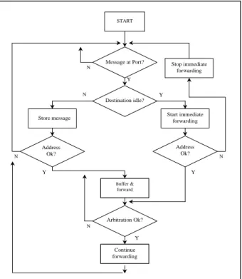
START Address Ok? Address Ok? Buffer & forward Arbitration Ok? Continue forwarding Stop immediate forwarding Y N N N Y N N Y Y Y
Figure 2. Simplified flow-chart of the CAN to CAN cut-through bridge operation. The immediate forwarding firstly reduces the message delay to the minimum possible. Secondly, as the message is forwarded with a new arbitration session on the other bus, the same message will be on two segments at the same time. That is, the total system length will be doubled without reducing the communication speed. With this method, the physical distance limitation of a CAN system can be exceeded.
While the immediate forwarding operation is in progress, when the arbitration field is received, the bridge applies address checking. The arbitration field is used for the address database in the bridge. Address checking is quite fast as in CAN systems acceptance filtering is used. The
filtering of the data is accomplished using an acceptance filter, which is an integral component of the CAN controller chip
.
After the address checking, if the message is decided to be forwarded, the cut-through bridge continues forwarding the rest of the message. If the message is not to be forwarded, that is, there are no nodes receiving that particular message on the other segment, the forwarding operation is immediately ceased. While the immediate forwarding is in progress, another message from a node on the destination segment may send a higher priority message at the same time and win the arbitration. In that case, if the message is to be forwarded the bridge will apply normal store and forward operation. This is a very low possibility at light and moderate bus loads, and may happen at heavy bus loads. Figure 2 shows the simplified flow-chart of the cut-through bridge operation.
Besides the advantages of this new application, a cut-through bridge causes extra traffic, because during the immediate forwarding if the message is not to be forwarded, the header of the message will have already been sent. This does not cause a significant problem, as it happens at light and moderate bus loads and most of the bandwidth remains unused. Besides this, the extra traffic will be as small as the header.
Another difference of the cut-through bridge can be seen with the error checking. While a normal bridge makes CRC checking before forwarding, it is not possible with cut-through bridging during the immediate forwarding. However, this error checking can still be completed on reception of the complete message and, in case of an error, the bridge can send an error frame. In addition, all the nodes in a CAN system have their own error recovery mechanisms. In terms of message consistency of the system, if any node on the destination or source side sends an error frame, as the bridge is transparent to the system, the error frame will be seen on both segments.
3. MODELLING AND SIMULATION
In order to compare the behavior and performance of the CAN systems, four different simulation models were used (5). The first model is a single segment extended CAN system. This model represents a segment extended by reducing
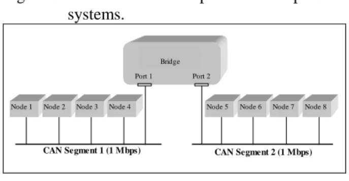
the bus speed from 1 Mbps to 500 kbps. The second model is another single segment CAN system with 1 Mbps bus speed without extension. The third model is a normal bridged CAN system. In this system, a normal bridge connects two CAN segments. The last one is a newly introduced cut-through bridged CAN model, which connects two 1 Mbps CAN segments. Figure 3 shows the model used for the single segment CAN system, and Figure 4 shows the model for the bridged CAN system.
C A N S e g m e n t
N o d e 4 N o d e 3
N o d e 1 N o d e 2 N o d e 5 N o d e 6 N o d e 7 N o d e 8
Figure 3. The model for 1Mbps and 500 kbps CAN systems.
CAN Segment 1 (1 Mbps) Node 4 Node 3
Node 1 Node 2 Node 5
CAN Segment 2 (1 Mbps) Node 6 Bridge
Port 1 Port 2
Node 7 Node 8
Figure 4. The model for normal and cut-through bridged CAN systems.
4. PERFORMANCE ANALYSIS
The performances of the four models have been compared through simulation results (5). In Figure 5, the delay characteristics of the four models are illustrated. As can be seen from the figure, the highest message delay is introduced by the single segment 500 kbps CAN system, because the bus speed of this model is lower. The normal bridged CAN system has a delay characteristic similar to the 500 kbps extended one. Although the segments have 1 Mbps speed, the normal bridge has to wait for the whole message to arrive before forwarding, and it makes the delay similar to the 500 kbps segment delay. On the other hand while the single segment extended system can reach the bus load up to 500 kbps, the bridged system can reach 1 Mbps bus load.
The least delay can be seen with the 1 Mbps single segment CAN without extension. The cut-through bridged CAN system has a very similar
0 0.5 1 1.5 2 2.5 3 3.5 0 20 40 60 80 100 Bus Utilisation (%) M e s s a g e d e la y ( M il is e c o n d ) 0.5 Mbps segment 1 Mbps segment Normal bridge Cut-thr bridge 0 20 40 60 80 100 120 0 1 2 3 4 5 6 7 8 9
Message Iteration Period (Milisecond)
U ti li s a ti o n ( % ) .5 Mbps segment 1 Mbps segment Cut -t hr bridge Normal bridge
delay characteristic to the 1 Mbps segment’s characteristic, while doubling the system length. This is the result of the immediate forwarding which allows the same message to appear on both buses at the same time, and the delay will be
Figure 5.
Figure 5. Message delay characteristics against bus utilisation.
reduced to the minimum possible. The cut-through bridged system shows similar characteristics at heavy bus loads. This happens because the probability to send messages by cut-through operation becomes less, and most of the messages will be stored and forwarded with normal bridge operation. At very high bus loads the immediate forwarding becomes almost impossible and both normal bridged and cut-through bridged system characteristics merge.
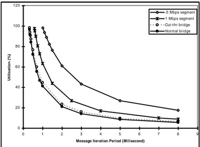
Figure 6. Bus utilisation against system message iteration period.
In Figure 6, the bus utilisation characteristics of the models are shown. The
highest utilisation is seen with the single segment 500 kbps extended CAN system, because of the lower bus speed. The single segment 1 Mbps CAN system has less bus utilisation than the extended one. As can be seen from the figure, the bridged systems always have less bus utilisation, as the total system load is divided by the bridge. The cut-through bridged CAN system has slightly higher utilisation, as the immediate forwarding causes extra traffic on the destination segment until the header is received and checked, when actually the message is not to be forwarded. At very high bus loads, that is low message iteration periods, the probability of immediate forwarding is very low, and again, both normal bridged and cut-through bridged system characteristics merge.
The performance of the cut-through bridge was also evaluated at different bus speeds. In order to compare the message delays, the SAE Benchmark values were used.
T (ms) D (ms) P1 50 5 P2 5 5 P3 10 10 P4 50 20 P5 100 100 P6 1000 1000
Table 1. Priority classification of SAE Benchmark message delays.
Table 1 shows the SAE (Society of Automotive Engineers) Benchmark message deadlines (D) in six groups. The message deadlines are shown in priority order from high to low (P1 to P6) with message transmission periods (T). The benchmark has 53 data types, and transformed benchmark signals contain all data types in 17 messages. These messages give about 85% bus utilisation at 125 kbps bus speed (6).
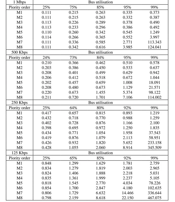
Table 2 shows message delays with priorities at various bus speeds and utilisation. Message numbers (Mn) are given in priority order. The bus speeds are chosen according to standard CAN specifications (1). As the delay values below 60% bus utilisation show slight differences, only the delays around 25% are given. The results show that cut-through bridged CAN systems meet the benchmark delay requirements. The shaded areas show the delays exceeding the corresponding benchmark values. It only occurs under extreme
o
~
_,._
-conditions, mostly over 90% bus utilisation. Although some messages seem to exceed some deadline values, according to the priority order they still meet the benchmark requirements. For example, at 125 kbps and 85% bus utilisation, cut-through bridged CAN system message delays with the lowest two priority messages exceed 5 ms
delay deadline. However, these delays are still much less than the lowest two priority message delay deadlines of the benchmark.
5. DISCUSSION AND CONCLUSION
In this paper, a brief explanation about the possible solutions to extend CAN systems is given,
1 Mbps Bus utilisation Piority order 25% 75% 85% 95% 99% M1 0.111 0.215 0.263 0.335 0.373 M2 0.111 0.215 0.263 0.332 0.387 M3 0.113 0.226 0.289 0.378 0.490 M4 0.113 0.233 0.296 0.386 0.492 M5 0.110 0.260 0.342 0.545 1.249 M6 0.114 0.266 0.365 0.552 3.997 M7 0.111 0.336 0.585 2.771 113.343 M8 0.111 0.342 0.616 3.985 124.041 500 Kbps Bus utilisation Piority order 24% 73% 84% 95% 99% M1 0.210 0.366 0.462 0.510 0.578 M2 0.203 0.386 0.450 0.533 0.637 M3 0.208 0.401 0.499 0.629 0.942 M4 0.206 0.412 0.518 0.672 1.044 M5 0.202 0.457 0.659 1.008 18.091 M6 0.208 0.480 0.673 1.129 21.571 M7 0.220 0.673 1.455 5.374 98.122 M8 0.211 0.720 1.701 7.106 114.002 250 Kbps Bus utilisation Piority order 25% 64% 80% 92% 99% M1 0.417 0.657 0.815 0.893 1.219 M2 0.432 0.718 0.770 0.988 1.259 M3 0.402 0.728 0.876 1.166 2.100 M4 0.398 0.695 0.972 1.250 1.835 M5 0.434 0.771 1.054 1.958 37.543 M6 0.419 0.876 1.079 2.113 58.951 M7 0.426 0.932 1.820 5.652 233.158 M8 0.428 1.055 2.060 8.914 345.509 125 Kbps Bus utilisation Piority order 25% 65% 85% 92% 99% M1 0.848 1.299 1.629 1.781 2.759 M2 0.834 1.279 1.819 2.003 2.965 M3 0.824 1.406 1.888 2.218 5.031 M4 0.835 1.361 1.999 2.237 5.105 M5 0.818 1.545 2.770 4.034 78.226 M6 0.854 1.700 2.847 4.180 102.635 M7 0.806 1.729 6.632 14.466 336.644 M8 0.798 2.159 8.618 22.150 467.075
Table 2. Message delays (ms) with priority and bus utilisation values for 1 Mbps, 500 Kbps, 250 Kbps, and 125 Kbps cut-through bridged CAN segments.
and a new extension method with cut-through bridging is introduced. The possibility of extending a CAN system beyond the present distance limitation without reducing the bus speed is explained. The advantage of using the Cut-through bridge can be seen clearer at light to moderate data loads. The results show that at low to moderate data loads, the cut-through bridged system has almost the same or slightly higher delay than that of the single segment 1 Mbps model, while doubling the system bus length. This is the result of the immediate forwarding feature of the cut-through bridge, which allows the same bit to appear on both buses at the same time. This is not possible with single segment extended or with normal bridged CAN systems. Therefore, the CAN system with a cut-through bridge will appear like a 1 Mbps segment with 80 m bus length, while for a single segment CAN it is only possible to have a maximum of 40 m bus length at 1 Mbps. As can be seen from these results the main novelty of the proposed model to the CAN is that the appearance of the same message on both CAN buses at the same time gives the advantage of having a CAN system with doubled system length. Simulation results also showed that the new model has much less message delay than the normal bridged one. This provides better performance for distributed real-time control systems. The simulation results were also compared with the SAE Benchmark values, and it was seen that the new model has characteristics in acceptable limits.
REFERENCES:
1. Bosch, CAN Specification, Version 2.0, Robert Bosch GmbH, Germany, 1991.
2. Thomas, G. M., Real-Time Performance of Bridged CAN Networks, CAN Newsletter, pp. 50-52, September 1998.
3. Halsall, F., Data Communications, Computer Networks and Open Systems, Fourth Edition, Addison-Wesley Publishing Company Inc, USA, 1996.
4. Kwok, C. & K., Mukherjee, B., Cut Through Bridging for CSMA/CD Local Area Networks, IEEE Trans. Commun., vol. 38, no. 7, pp. 938-942, 1990.
5. Tenruh, M., Stipidis, E., English, M. J., Design and Software Implementation of a CAN/CAN Cut-through Bridge, Proc. 6th ICC Conference, Italy, pp. 10_07-10_13, 1999.
6. Lawrenz, W., CAN System Engineering From Theory to Practical Applications, Springer-Verlag Inc., New York, 1997.