A Novel EBG Structure to Improve Isolation in
MIMO Antenna
Ahsan Altaf∗, M. A. Alsunaidi†, and Ercument Arvas∗
∗Electrical-Electronics Engineering Department, Istanbul Medipol University, Istanbul, Turkey. †Electrical Engineering Department, King Fahd University of Petroleum and Minerals, Dhahran, SaudiArabia.
Email: [email protected]
Abstract—A new, and advanced Electromagnetic Band Gap (EBG) structure is reported to reduce the mutual coupling between two tightly spaced rectangular patch antennas. The EBG structure provides more than 20 dB reduction in mutual coupling without degrading far-field patterns, gain, or bandwidth.
Index Terms— RFID, Radar, MIMO systems, millimeter wave (mmWave), mutual coupling (MC), electromagnetic band gap (EBG ) structures, fifth generation (5G).
I. INTRODUCTION
In modern communication systems, there is an ever present demand for size reduction. However, miniaturization often gives rise to undesirable Mutual Coupling (MC); the elec-tromagnetic interactions between antennas. Antenna array performance is compromised by MC. Mutual coupling often degrades gain, input impedances, radiation patterns, and side lobe levels [1]. MIMO systems are particularly impacted by MC due to a tight spacing between radiating elements [2]. Moreover, in applications such as Imaging Radar Systems, MC needs to be minimized due to antenna proximity [3]. Hence, many solutions have been suggested to reduce MC. These solutions include EBG [4], parasitic element slots [5], Defected Ground Structures (DGS) [6] and slotted ground planes [7]. Of these, EBGs tend to better preserve radiation pattern and bandwidth. They reduce the MC among radiating elements as they are periodic structures with little surface wave propagation admittance. To suppress surface waves a wideband EBG structure is needed to improve isolation. To meet the requirements discussed above, a new compact EBG structure is presented. The structure is designed to work around 24 GHz. The resulting wideband system is simulated using COMSOL Multiphysics software.
Fig. 1: The MIMO antenna configuration.
Fig. 2: A unit cell of the EBG structure. II. DESIGN
A. MIMO Antenna
A two element array is designed. The array elements are rectangular patch antennas. The antennas are designed to operate around 24 GHz. The array is printed on Duroid 5880. The substrate permittivity, εr, is 2.2 and has a thickness of 0.5
mm. The patch antennas are 3.3 mm × 4 mm. The separation between antennas, edge-to-edge, is 0.45λo (5.625 mm). The
antennas are probe fed. The probe coaxial cable is Teflon filled (εr= 2.1). The inner conductor diameter is 0.6 mm and the
outer conductor diameter is 2 mm. The feed point is selected to provide 50 Ω input impedance. Figure 1 shows the proposed MIMO antenna setup.
B. EBG Structure
A unit cell of the EBG structure is shown in Figure 2. It is two H-shapes connected. One is rotated 90◦. The design parameters are recorded in Table I. A five by three array of EBG unit cells is placed between the antennas. In-addition, six metallic strips are also introduced within the array. The structure of an array is shown in Figure 3. Often, the electro-magnetic properties of a surface are modified by utilizing a pattern on the surface. Naturally, the surface impedance will vary with frequency. An EBG structure acts as a filter to impede surface waves. The structure can be modeled as an LC network and the parameters of the EBG structure can be modeled with the formulas presented in [8] and [9]. In order to study the EBG structure’s transmission characteristics, a transmission line test was conducted using COMSOL. The full wave electromagnetic simulation includes the effects of a Table I: EBG unit cell design parameters.
Parameters l1 l2 l3 l4 w1 w2 w3
Value (µm) 656 594 750 62.5 500 187.5 62.5
105
Fig. 3: The EBG array.
finite substrate, metal thickness, and all losses. It was found that a bandgap for the EBG structure shown in Figure 3 exists in the band 22-27 GHz.
III. RESULTS ANDDISCUSSION
As expected, the introduction of the EBG did not signifi-cantly alter the return loss of the antennas. A Comparison of the different antenna parameters is listed in Table II. Table II: Key antenna performance parameters.
Parameters With EBG Without EBG Bandwidth 290 MHz 270 MHz
Gain 7.88 dBi 7.66 dBi
A. Isolation Coefficient:
Isolation between the antennas can be measured in terms of parameter S12. At the center of the band, the unmodified
antenna has an S12 of -24 dB. By introducing the EBG
structure, S12 decreases to around -53 dB as shown in the
Figure 4.
Fig. 4: Antennas Isolation
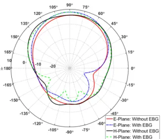
Fig. 5: Radiation pattern B. Radiation Pattern
Figure 5 illustrates the radiation pattern at resonance. The EBG structure does not degrade the radiation pattern signifi-cantly.
IV. CONCLUSION
In this paper, a novel EBG structure was designed. The EBG structure was used to improve isolation between patch antennas. An approximate 20 dB reduction in mutual coupling was achieved while maintaining key antennas performance parameters.
REFERENCES
[1] S. Farsi, H. Aliakbarian, B. Nauwelaers, and G.A.E. Vandenbosch, Mutual coupling reduction between planar antenna by using a simple microstrip U-section, IEEE Antennas Wireless Propag. Lett. 11 (2012), 15011503. [2] Yue Gao; Runbo Ma; Yapeng Wang; Qianyun Zhang; Clive Parini,
Stacked Patch Antenna With Dual-Polarization and Low Mutual Cou-plingfor Massive MIMO, IEEE Transactions on Antennas and Propaga-tion, Vol. 64, Issue: 10 Pp: 4544 - 4549, March 2016.
[3] Q. Lei, Z. Fei, X. Ke, C. Shun-Lian, and M. Jun-Jie, Transmit and receive isolation improvement of antenna arrays by using EBG structures, IEEE Antennas Wireless Propag. Lett., vol. 11, pp. 9396, Jan. 2012. [4] Lee, J. Y., S. H. Kim, and J. H. Jang, Reduction of mutual coupling in
planar multiple antenna by using 1-D EBG and SRR structures, IEEE Transactions on Antennas and Propagation, Vol. 63, No. 9, 41944198, Sept. 2015.
[5] S. Soltani and R. D. Murch, Designing planar MIMO antennas using a novel canonical dual port antenna, in Proc. IEEE Int. Symp. Antennas Propag. Soc., 2014, pp. 5758.
[6] Nguyen Khac Kiem, Huynh Nguyen Bao Phuong, Quang Ngoc Hieu, and Dao Ngoc Chien, A Novel Metamaterial MIMO Antenna with High Isolation for WLAN Applications, International Journal of Antennas and Propagation, Jan 2015.
[7] C.-Y. Lui, Y.-S. Wang, and S.-J. Chung, Two nearby dual-band antennas with high port isolation, inProc. IEEE Antennas Propag. Soc. Int. Symp. (AP-S 2008), San Diego, CA, 2008, pp. 14.
[8] D. Sivenpiper, L. Zhang, R. F. Broas, N. G. Alexopoulos and E. Yablonovitch, High-impedance electromagnetic surface with a forbidden frequency band, IEEE Trans Microw. Theory Tech., vol. 47, No. 11, pp. 2059-2074, Nov. 1999.
[9] M. Krkkinen and P. M. T. Ikonen, Finite-difference time domain modeling of frequency selective surfaces using impedance sheet conditions, IEEE Trans. Antennas Propag., vol. 53, no. 9, pp. 2928 2937, Sep. 2005.