ENERGY EFFICIENT IP-CONNECTIVITY
WITH IEEE 802.11 FOR HOME M2M
NETWORKS
a thesis
submitted to the department of computer engineering
and the graduate school of engineering and science
of bilkent university
in partial fulfillment of the requirements
for the degree of
master of science
By
˙Ihsan Mert ¨
Oz¸celik
July, 2014
I certify that I have read this thesis and that in my opinion it is fully adequate, in scope and in quality, as a thesis for the degree of Master of Science.
Assoc. Prof. Dr. ˙Ibrahim K¨orpeo˘glu (Advisor)
I certify that I have read this thesis and that in my opinion it is fully adequate, in scope and in quality, as a thesis for the degree of Master of Science.
Prof. Dr. ¨Ozg¨ur Ulusoy
I certify that I have read this thesis and that in my opinion it is fully adequate, in scope and in quality, as a thesis for the degree of Master of Science.
Prof. Dr. Ahmet Co¸sar
Approved for the Graduate School of Engineering and Science:
Prof. Dr. Levent Onural Director of the Graduate School
ABSTRACT
ENERGY EFFICIENT IP-CONNECTIVITY WITH IEEE
802.11 FOR HOME M2M NETWORKS
˙Ihsan Mert ¨Oz¸celik M.S. in Computer Engineering
Supervisor: Assoc. Prof. Dr. ˙Ibrahim K¨orpeo˘glu July, 2014
Machine-to-machine communications (M2M) technology enables large-scale com-munication and networking of devices of various kinds including home devices and appliances. A critical issue for home M2M networks is how to efficiently integrate the already existing home consumer devices and appliances into an IP based wireless M2M network with least modifications to existing components. Due to its popularity and widespread usage in closed spaces, Wi-Fi is a good alternative as a wireless technology to enable M2M networking for home devices. This thesis addresses the energy-efficient integration of home appliances to a Wi-Fi and IP based home M2M network. Towards this goal, we first propose an integration architecture that requires least modifications in existing components. Then, we propose a novel long-term sleep scheduling algorithm to be applied to-gether with the existing 802.11 power save mode (PSM). The proposed scheme utilizes the multicast DNS (mDNS) protocol to maintain device and service avail-ability when devices go into deep sleep mode.
We implemented our proposed architecture and algorithm as a prototype to build an M2M network of home appliances as a test-bed. We performed various experiments on this test-bed to evaluate the proper operation and energy savings of our proposal. We also did extensive simulation experiments for larger-scale scenarios. As a result of our test-bed and simulation experiments, we observed energy savings up to 70% compared to the existing infrastructure which applies no sleep mechanism, and up to 20% compared to standard 802.11 PSM scheme, while ensuring device and service availability at the same time.
Keywords: Home M2M Networks, Smart Home, Internet of Things, Smart Appli-ances, Sleep Scheduling, IEEE 802.11 Power Save Mode, Embedded Networking.
¨
OZET
EV M2M A ˘
GLARI ˙IC
¸ ˙IN IEEE 802.11 TABANLI ENERJ˙I
VER˙IML˙I IP-BA ˘
GLANAB˙IL˙IRL˙I ˘
G˙I
˙Ihsan Mert ¨Oz¸celik
Bilgisayar M¨uhendisli˘gi, Y¨uksek Lisans
Tez Y¨oneticisi: Assoc. Prof. Dr. ˙Ibrahim K¨orpeo˘glu Temmuz, 2014
Makinalar arası ileti¸sim (M2M), akıllı ev e¸syaları dahil ¸ce¸sitli t¨urdeki cihazların olu¸sturdu˘gu geni¸s ¨ol¸cekli a˘glara olanak sa˘glar. Ev M2M a˘gları i¸cin kritik mesele, ev e¸syalarının IP tabanlı bir kablosuz M2M a˘gına enerji verimli ve ¸su anki ciha-zlarda minimum de˘gi¸sikle nasıl entegre edilece˘gidir. Ev M2M a˘glarının hızlı ente-grasyonu ve yaygınla¸sması i¸cin Wi-Fi ideal bir ¸c¨oz¨um olabilir ¸c¨unk¨u g¨un¨um¨uzde Wi-Fi ev a˘glarında pop¨uler ve yaygın olarak kullanılmaktadır. Fakat, Wi-Fi ‘ın ¸su anki alt yapısının M2M a˘glarına uygun olması i¸cin enerji tasarruf mekaniz-malarına ihtiyacı vardır.
Bu tez, Wi-Fi teknolojisinin enerji verimli bir ¸sekilde akıllı ev sistemlerinde kullanılacak g¨om¨ul¨u cihazlara nasıl entegre edilece˘gini g¨osterir. Tezde, ev M2M a˘glarında enerji tasarrufu i¸cin IEEE 802.11 g¨u¸c tasarruf modu (PSM) ve uyku zamanlama algoritması tabanlı yeni bir yakla¸sım ¨onerilmektedir. Bu yakla¸sım, IEEE 802.11 MAC katmanında de˘gi¸siklik yapılmadan ger¸ceklenir. Yakla¸sımın ger¸ceklenmesinde cihazların eri¸silebilirli˘gi etkilenmeksizin mDNS pro-tokol mesajlarından da faydalanılır.
Tezdeki ¨onerilen yakla¸sım, bir ev M2M a˘gına prototip olarak uygulanmı¸stır. Bu prototiplerle ve hazırlanan simulasyonlarla, ¨onerilen yakla¸sımın performans de˘gerlendirmesi yapılmı¸stır. Prototip ¨uzerinde yapılan testlerin ve simulasyon-ların sonu¸clarna g¨ore, herhangi bir enerji tasarruf mekanizması kullanmayan stan-dart altyapıya kıyasla yakla¸sık %70, IEEE 802.11 g¨u¸c tasarruf moduna kıyasla %20 enerji tasarrufu sa˘glandı˘gı g¨or¨ulm¨u¸st¨ur.
Anahtar s¨ozc¨ukler : Ev M2M A˘gları, Akıllı Ev, Nesnelerin Interneti, Uyku za-manlama, IEEE 802.11 PSM, G¨om¨ul¨u A˘glar.
Acknowledgement
In the first place, I would like to express my gratitude to my supervisor As-soc. Prof. Dr. ˙Ibrahim K¨orpeo˘glu for his guidance and invaluable support in supervision of this thesis. I would like to thank especially for his incredible effort, understanding and constant encouragement in the process. Working with him has always been a pleasure.
I would like to thank to Prof. Dr. Ozg¨¨ ur Ulusoy and Prof. Dr. Ahmet
Co¸sar for kindly accepting to spend their valuable time to review and evaluate my thesis.
I would like to express my thanks to ARC¸ EL˙IK A.S¸. for permitting and supporting me to continue my M.S. education and research along with my occu-pational commitments.
I also thank to Scientific and Technical Research Council of Turkey (T ¨UB˙ITAK) for financially supporting me in my graduate education and par-tially supporting this work with project 113E274.
Contents
1 Introduction 1
2 Background and Related Work 5
2.1 Related Work . . . 5
2.2 Overview: IEEE 802.11 Power Save Mode . . . 7
2.3 Overview: Multicast Domain Name Service (mDNS) . . . 8
3 Proposed System Architecture 10
3.1 Proposed Wi-Fi Setup and Authentication Scheme . . . 14
3.2 Proposed Software Architecture . . . 15 3.3 Implementation Details . . . 17
4 Proposed Long-Term Sleep Scheduling Scheme 21 5 Experiments and Evaluation 29
5.1 Testbed Experiments . . . 29 5.2 Simulation Experiments . . . 35
CONTENTS vii
List of Figures
2.1 mDNS query for http. tcp.local and related responses. . . . 9
3.1 Integration model of Wi-Fi to embedded devices. . . 11
3.2 Data frame format in the communication between appliance and Wi-Fi module. . . 12
3.3 The proposed home M2M network. . . 13
3.4 Authentication process. . . 14
3.5 Proposed software stack. . . 16
3.6 The code snippet to start Soft AP. . . 18
3.7 Web page on the Wi-Fi module for configuration mode. . . 19
3.8 The code snippet from thread function of http server. . . 20
4.1 State diagram for an individual device in a home M2M network. . 23
4.2 Announce algorithm. . . 24
4.3 State updating algorithm. . . 25
LIST OF FIGURES ix
4.5 A sample scheduling of sleep states by the proposed algorithm for
nodes in a home M2M network. . . 26
4.6 Rdata frame which conveys all sleep-scheduling related parameters encapsulated in mDNS response packet. . . 27
5.1 Current consumption in IEEE 802.11 power save mode. . . 30
5.2 Energy consumption without the PSM mode. . . 32
5.3 Energy consumption with our proposed scheme. . . 33
5.4 Energy consumption comparison between the PSM mode and our sleep scheduling applied with different sleep periods. . . 34
5.5 The effect of activeness factor. . . 38
5.6 The evaluation of various duty cycles. . . 39
5.7 The effect of number of devices. . . 41
List of Tables
3.1 UART communication settings between Wi-Fi module and home
appliance. . . 17
3.2 Commands for communication on UART. . . 17
4.1 Sample usage of device types. . . 28
5.1 Comparison of energy consumption values for a device while tcycle
is 5s and number of devices is 5 in the network. . . 34 5.2 Notation. . . 35
5.3 Energy consumption values used in formula for T = 400 seconds. . 36
5.4 Comparision between proposed approach and the other cases for
different n-devices in terms of energy efficiency. . . . 40 5.5 The activeness factor (k)s assigned to appliances. . . . 41
Chapter 1
Introduction
Tremendous growth and advances in device and communication technologies have enabled the development of a new networking paradigm, machine-to-machine (M2M) communications, which has recently received considerable attention. In numbers, it is estimated that over 50 billion of devices will be connected to the Internet by 2020 [1]. It is envisioned that networks will shift from current human-to-machine communications to the machine-human-to-machine paradigm with the rapid penetration of embedded devices in home and business surroundings. This re-quires an easy and flexible attachment of devices to Internet, a high capability for autonomous registration and discovery of devices, and a low power opera-tion to enable green IT. However, the integraopera-tion of huge number of devices and machines with all different kinds into the existing IT systems in a cost-effective, energy-efficient and automated manner is still an open research issue. This is also the case for home M2M networks where home appliances and devices are connected with each other and Internet to enable various M2M applications.
There are various use-cases and applications for home M2M networks, some of which are:
• Controlling and monitoring household appliances remotely: Using home M2M networks, any household appliances can be controlled and monitored remotely. For example, coffee machine can be run remotely by a smart
phone. As another example, users can be notified via their smart TVs or tablets when washer finishes its washing cycle.
• Lighting: Home M2M networks allow homeowners to remotely control their light bulbs connected to such a network.
• Smart Grid and Energy management: Home M2M networks can be eval-uated as the pillar of smart grid concept. Communication between the electricity grid and home M2M networks can provide homeowners to auto-matically shift energy use to periods of low-cost electricity.
• Heating, ventilation and air conditioning systems (HVAC): As an example, HVAC systems provide homeowners to control the home’s heating systems remotely via thermostats connected to a home M2M network.
Existing IT systems with a wired Ethernet-like or wireless ZigBee-based distri-bution network are either inflexible, costly or require additional special gateways to connect machines and devices to Internet. Additionally, the usage charges for existing 3G networks and other services are expensive for the end users [2]. Instead, using the existing Wi-Fi network infrastructure in implementing and deploying an embedded device network can save a lot of hardware costs, since Wi-Fi is already available and widely used in daily life, especially in homes and offices. Therefore, Wi-Fi is a very attractive solution for the remote transmis-sion and wireless monitoring needs of embedded devices in smart home and office systems. On the other hand, Wi-Fi consumes more power compared to other wireless technology alternatives like Zigbee or Blueetooth [3].
M2M applications require an easy to deploy system that enables communica-tion between machines and human-machine interface devices such as smart tablets and phones. To meet this requirement, in this thesis we investigate the use of Wi-Fi technology and existing Wi-Fi infrastructure in connecting home consumer electronics devices, appliances and machines to each other and the Internet. We focus on how we can integrate Wi-Fi technology into embedded devices in an easy, modular, flexible and energy-efficient manner. We also propose a sleep scheduling algorithm based on IEEE 802.11 power save mode (PSM) to reduce the energy
consumption of Wi-Fi integrated consumer devices and machines. Our proposed sleeping mechanism and policy favors energy-constrained devices by forcing them to go into sleep mode (long and deep sleep) for a longer period of time. Favor-ing such devices provides compliance with tight standby energy regulations and radically increases the lifetime of battery-powered devices.
The standard IEEE 802.11 power save mode (PSM) minimizes device energy consumption by allowing a device to de-activate its wireless interface periodically while the associated access point buffers the incoming packets to the device. Although applying long sleep periods in addition to IEEE 802.11 power save mode hugely reduces energy consumption, this causes the devices to lose their service availability while they are in sleep mode. When some devices are in long sleep, other devices and applications cannot be aware of the existence of those sleeping devices in the network. Additionally, sleep scheduling strategies need to make a trade-off between latency and energy saving.
The contributions of this thesis are manifold. It first analyzes the impact of IEEE 802.11 power save mode (PSM) on energy saving by enabling the PSM mode in a Wi-Fi network of home consumer devices and machines. The thesis also shows how such devices and machines can be connected together and to the Internet in an easy, secure and modular way. A system architecture is proposed to integrate Wi-Fi to embedded home devices in an easy manner. As mentioned earlier, this study also proposes a long-term sleep scheduling (duty-cycling) algo-rithm in addition to the use of the standard IEEE 802.11 PSM mode for home M2M networks. The objective is to minimize energy consumption with no change in the standard 802.11 MAC and PSM protocols, since such changes in 802.11stan-dard would reduce the rapid and widespread deployment of the proposed scheme. Furthermore, the proposed scheme is considering not losing service availability, while applying sleep scheduling and trying to reduce energy consumption.
We implemented our proposed architecture for home M2M networks on home appliances and we performed experiments on this test-bed for measuring energy consumption of Wi-Fi modules in order to evaluate the performance of our pro-posed sleep scheduling approach. To evaluate scalability of the propro-posed approach
with a large number of stations, we also conducted some simulation experiments using real energy consumption data from testbed experiments. The experimen-tal results showed that the proposed sleep scheduling scheme achieves energy conservation of up to 71% compared to the existing infrastructure which applies no sleep mechanism, and up to 20% compared to standard 802.11 PSM scheme, while at the same time keeping device and service availability. Furthermore, our prototype implementation on home appliances also validates the argument that the proposed scheme is feasible to real life deployment.
The remainder of the thesis is organized as follows. After the related work is represented in Chapter II, Chapter III describes the proposed system architecture and how we can integrate a machine to a Wi-Fi network and make it part of the Internet to enable M2M communication. Then, Chapter III includes the imple-mentation details and the proposed authentication process, which is followed by our proposed sleep scheduling scheme on top of IEEE 802.11 power save mode in Chapter IV. Finally, experimental results are presented and discussed in Chapter V. Chapter VI concludes the thesis.
Chapter 2
Background and Related Work
2.1
Related Work
Numerous studies have been conducted in home M2M communication from sys-tem architectural challenges concerning the real-life practicality to various syssys-tem integration models and energy efficiency in wireless communication.
Architectural challenges in home M2M networks are underlined in [4], [5]. These studies commonly point out two difficulties in the deployment of such networks, which are essential need of low energy consumption for communication and requirement for intermediate protocol translation gateways. The argument about the practicality of such gateways is supported in [6] by indicating that how to connect non-IP based M2M components to the existing Internet backbone is still an open issue. In [4], various M2M radio technologies such as ZigBee, Bluetooth Low Energy and Wi-Fi are compared and concluded that Wi-Fi is the most accepted protocol for wireless communication inside of the homes and Wi-Fi eliminates the requirement of protocol translation gateways due to being IP-enabled, although Wi-Fi requires more power than other alternatives. [4] also states that it is important to manage home networks so that resource-constrained home devices use their energy efficiently. In a similar manner, different M2M radio technologies are investigated in [7] and again the high energy consumption
of Wi-Fi is pointed out as a crucial drawback of Wi-Fi for home M2M networks. A different study, [5], also emphasizes low power consumption of the radio as an important characteristics of home M2M networks.
How to integrate Wi-Fi technology into embedded devices in homes is il-lustrated in [8], [9]. The authors in these studies propose a system model to provide wireless monitoring and remote control for embedded devices by gaining IP-connectivity. How to configure such smart devices to connect a specific AP with a password specified by user is an open issue in their studies. High power consumption of their models is also a bottleneck for real life deployment and there is no procedure for the reduction of power consumption in [8],[9]. Moreover, a system model for embedded web server-based home appliance networks based on Ethernet is presented and it is verified through a prototype working with real appliances in [10]. However, this model does not use any radio technologies in communication and consequently it is not effective in terms of comfort and cost. In the same context, there are lots of studies for embedded M2M smart home systems which use 3G infrastructure in physical layer. In our study, we do not consider cellular systems for home M2M networks due to its cost disadvantage.
To alleviate high energy consumption of Wi-Fi, the 802.11 standard already defines a power save mode [11]. Basically, 802.11 PSM proposes a scheme to turn stations while they are not actively communicating and to wake up from the sleep state periodically for listening traffic announcements. There is a lot of 802.11 PSM related studies, which are aimed at minimizing energy consumption in M2M networks. We can categorize them into two groups: one requiring changes on the AP side [12], [13]; and the other one about strategies on the client side [14],[15],[16],[17]. In this section, the 802.11 PSM related enhancements on the AP side is not analyzed since we consider sleep scheduling strategies on the client side to be applied on top of the conventional WLAN infrastructure in homes. In [14], DeepSleep is proposed for M2M networks based on the IEEE 802.11 by favoring low energy devices for higher priority in channel allocation and by forcing them to sleep for a longer period of time. Their proposed strategy necessitates modifications on the standard medium access control layer of the 802.11. Hence, deploying such an enhancement in a practical way is problematic since the MAC
is typically implemented in hardware. Instead of a fixed wake-up interval, [15] proposes traffic-aware duty cycles. Similarly, [16] chooses an adaptive interval time for sleeping depending on the time of the session activity at IP layer.
2.2
Overview: IEEE 802.11 Power Save Mode
It is common in wireless communications to turn off transmitters to minimize power consumption while there is no active communication and wake them up when there are data packets to transmit or receive. Since a station in 802.11 power save mode (PSM) cannot know the exact time at which a packet will be transmitted to it, it is challenging to wakeup just at the exact time for receiving the packets. Hence, the IEEE 802.11 standard supports the PSM as follows.
First of all, the IEEE 802.11 PSM can be operated in infrastructure mode or ad-hoc mode. The detailed operations of two modes are partially different. This study in the thesis focuses on the power saving mechanism in infrastructure mode since our system model assumes that there is a conventional access point (AP) to monitor current mode of each station. In the infrastructure mode, the IEEE 802.11 PSM supports two types of modes: active and power-saving (PS) modes. Compared with PS mode, a station in active mode is fully powered and consequently may send and receive packets at any time, unsurprisingly it consumes extremely higher energy.
At the other side of the spectrum, a station in PS mode only wakes up pe-riodically to check whether there are any incoming packets from the AP. The station always notifies its AP when switching modes. The home AP periodically sends beacons spaced by a static beacon interval (BI). A station in power-save mode should monitor these frames. Once every beacon interval, the AP trans-mits a beacon frame containing a traffic indication map (TIM), which contains the identifiers (ID) of those stations in PS mode for which there are buffered unicast packets waiting in the AP. Upon hearing its ID, a station in PS mode should stay awake for the remaining beacon interval to receive packets destined
to it.
Power saving mechanism in ad-hoc mode, where packet store and forward and the timing synchronization has to be done in a distributed manner, is more complicated. Details for ad-hoc networks can be found in [11].
2.3
Overview: Multicast Domain Name Service
(mDNS)
Connected appliances need to be accessible and usable by each other and ordinary users through familiar software after joining a home M2M network. That is, such appliances should be seamlessly integrated to local home M2M networks by enabling the discovery of devices and their services. To meet this requirement, multicast DNS (mDNS) is established by the IETFs Zeroconf initiative at the application layer [18].
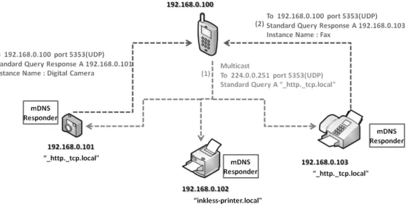
Multicast Domain Name Service provides DNS operations on the local link without any conventional unicast DNS server. The major difference between mDNS and the conventional unicast DNS is that the client transmits its DNS query message to a multicast address instead of sending to a DNS server. After sending the query to this multicast address on the local network, all target devices with mDNS server can hear the multicast query message and respond with a packet which consists of their services and IP addresses. Similar to DNS, mDNS uses UDP packets and its packet format is based on the DNS packet format. In mDNS, the multicast IPv4 address is 224.0.0.251 and the UDP port number is 5353.Figure 2.1 illustrates how a mDNS query with the service http. tcp.local is answered by mDNS responders which are digital camera and fax in this case.
mDNS has two popular implementations which are the Apple Bonjour[19] and Linux nss-mdns services. These implementations are not practical for home appliances in terms of memory space complexity. In this thesis, Broadcom’s Gedday library is adapted as a lightweight and memory-efficient implementation
Figure 2.1: mDNS query for http. tcp.local and related responses.
of mDNS running on top of RTOS. Additionally, mDNS test software to monitor all devices and their services has been developed as part of the thesis.
Chapter 3
Proposed System Architecture
Prevalently, wireless network cards having USB interface are used in smart TVs, PCs and laptops. However, embedded devices in industry such as home appli-ances, industrial instruments, intelligent actuators, smart sensors, etc., generally do not have a USB interface or need complex USB driving programs in order to use the wireless network card. Therefore, such wireless network cards are not very practical for embedded devices and this brings a challenge while integrating Wi-Fi into home embedded devices.
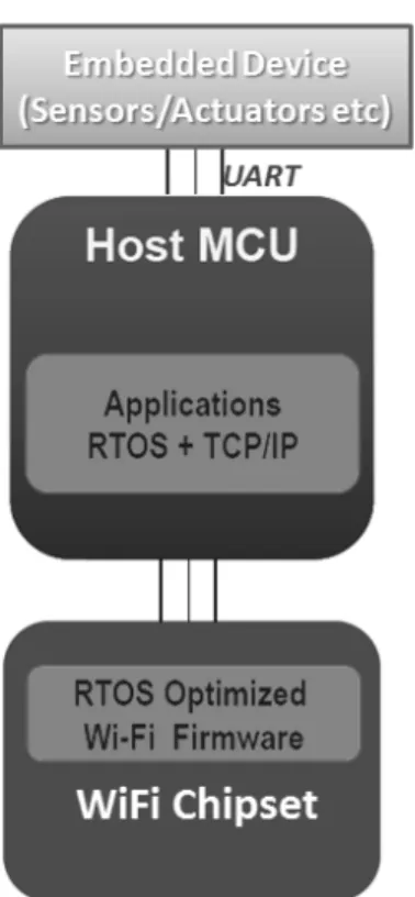
To overcome this challenge of integrating Wi-Fi into existing home embedded devices in an easy, modular and efficient manner, so that home appliances can form an M2M network, in this thesis we propose and implement the system ar-chitecture shown in Figure 3.1. Home embedded devices are powered by one or more main processing cores that are typically either microcontrollers or digital signal processors (DSP). Washer, dryer, oven, set-top-box, air conditioner, digital camera, intelligent instrument, etc., exemplify this architecture. Since the micro-controllers or DSPs include serial communication interface, using the architecture proposed in Figure 3.1, embedded devices can easily be integrated with Wi-Fi.
In our proposed architecture, an embedded device communicates with a sep-arate Wi-Fi module via a serial communication interface (for example, UART).
Figure 3.1: Integration model of Wi-Fi to embedded devices.
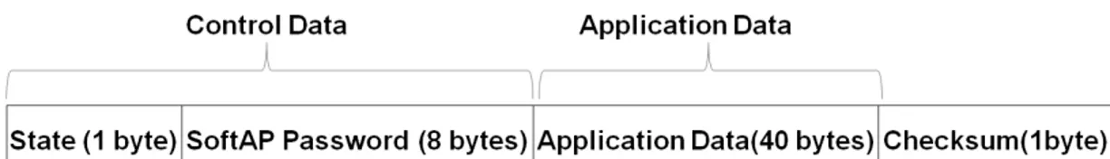
Straightforwardly, the Wi-Fi module can be thought as UART-to-wireless con-verter. On the serial interface, a device-specific communication protocol between Wi-Fi module and embedded device is used. The packet crossing the interface consists of two parts: control data and application data. Frame format is shown in Figure 3.2. Control data enables an embedded device to control the Wi-Fi module, for example to open/close the Wi-Fi antenna and switch between Soft AP mode and station mode (STA). It also includes device identifier (ID), which provides Wi-Fi module to learn device type. Application data refers to device specific data, and it is defined by the user application. It is the raw application data between a user terminal (for example, a smart phone) and the embedded device. For instance, the temperature inside an oven is carried as part of appli-cation data. Implementation details about the communiappli-cation protocol between the Wi-Fi Module and home embedded device are given in Section 3.2.
Figure 3.2: Data frame format in the communication between appliance and Wi-Fi module.
consists of a smart tablet and home appliances such as washer, oven, dryer, dish-washer and fridge. All Wi-Fi modules integrated to the appliances have the same generic software, which periodically reads application data defined in Figure 3.2 via the UART interface. A Wi-Fi module communicates with an application running on a smart tablet by using TCP sockets. If there is any change on the appliance, the change is indicated by generating and sending a data packet from the appliance. This data is then read by the Wi-Fi module over the UART and sent through the TCP connection to the respective tablet application. The ap-plication interprets the data and updates the GUI. For instance, if washing state inside a washer is updated, the washer indicates the new state in the respective field of a new data frame created. Since Wi-Fi module periodically reads the data frame from the appliance, it will be aware of this update and it will inform the monitoring application possibly running on a smart tablet.
Figure 3.3 illustrates overall system architecture and use-case scenario, in which there are monitoring and control applications running on smart phones or tablets. Appliances are intelligent instruments or smart sensors that communicate with those monitoring and control applications via Wi-Fi modules.
In this manner, the appliances form a Wi-Fi wireless LAN (WLAN). Use of wireless communication for applications eliminates complicated wiring. All appliances in the WLAN are connected to a wireless access point (AP) which en-ables communication among appliances and also between appliances and a wired network. The wired network can be a wired LAN (Ethernet) or a WAN. The connection technology of AP to the WAN and the rest of Internet can be PSTN, ADSL, DDN, Fiber, or 3G. In this manner, multiple Wi-Fi-enabled home appli-ances can form an M2M network spanning both wireless and wired LAN/WAN
Figure 3.4: Authentication process.
networks. Then, a local or remote monitoring and control application can access the appliances via this M2M network.
3.1
Proposed Wi-Fi Setup and Authentication
Scheme
Before sending and receiving data in the home network, Wi-Fi enabled embedded device needs to connect to an access point in the home, which has a specific SSID and password. Since embedded devices usually do not have an input/output ap-paratus such as a terminal apap-paratus or a GUI interface, setting up authentication information on the embedded device to connect it to a specific home WLAN is not an easy task. As part of our solution to this problem, we benefit from Software enabled Access Point (Soft AP) mode and embedded HTTP web server on Wi-Fi module to configure an embedded device to connect to a specific home WLAN.
Soft AP is enabled by software on the module to make a wireless station work as the access point. That is, it creates a wireless hotspot. To secure the proposed configuration process, Soft AP has a WPA security key in an embedded device which has a display to show at least 8 characters. A user can connect to the Soft AP of the embedded device and send the home WLAN SSID and password to Wi-Fi module via the embedded HTTP server running on the module. Then the Wi-Fi module integrated to embedded device switches to STA mode and connects to the home WLAN. This procedure is elaborated in Figure 3.4. Implementation details of the proposed setup mode are given in Section 3.3.
Alternatively, Wi-Fi Protected Setup (WPS) could be applied to enter a wire-less AP SSID and password into an embedded device. In WPS Push Button Configuration (PBC) method [20], users start the configuration procedure by pressing buttons on both the AP and the client device. Using the WPS push button seems easy in terms of user experience to add an embedded device to a wireless home network without entering long pass-phrases. However, WPS has a security flaw caused by brute force attacks [21]. Additionally, another secu-rity concern arises in the scenario of neighbor home networks. That is embedded device can be accidently connected to a WPS-enabled wireless network in a neigh-boring home. Due to these reasons, we prefer the use of Soft AP and embedded HTTP server on the Wi-Fi module instead of using WPS Push Button as part of our authentication scheme.
3.2
Proposed Software Architecture
The proposed software system to be used in our integration solution mainly con-sists of RTOS, TCP/IP Stack, Wi-Fi functions and Platform functions. In our implementation, Free RTOS [22] is used to serve real-time application requests, which basically provides thread, semaphore, mutex and timer management func-tions. For the implementation of IP communication, we use lwIP - lightweight TCP/IP, which is appropriate for use in embedded systems with tens of kilobytes of RAM [23]. Finally, Platform functions in the proposed stack allow managing
Figure 3.5: Proposed software stack.
hardware components such as UART, SPI, I2C, GPIO and Watchdog Timer. Fig-ure 3.5 shows the software system used on the integration architectFig-ure illustrated in Figure 3.1.
To implement our proposed authentication scheme, we modify the conven-tional Wi-Fi functions to configure a Soft AP which has WPA security key ran-domly generated in each Wi-Fi setup. We also define and implement our own communication protocol over UART to communicate with home embedded de-vices. The proposed protocol over UART provides communication between appli-ance and the Wi-Fi module integrated to the appliappli-ance. UART settings used in this protocol are explained in Table 3.1. Three types of commands are sent from the Wi-Fi module to home appliance, which are SINGLE READ, WRITE and FULL READ. SINGLE READ reads one value at a location of the data frame explained in Figure 3.2. For example, assuming that the temperature inside an oven is at location 26 of the data frame, the Wi-Fi module sends the 5-byte com-mand, which is 64, 0, 0, 26, 165 to read the temperature. The command WRITE enables Wi-Fi module to modify any value of the data frame on the appliance. Lastly, the command FULL READ retrieves all 50 bytes of the data frame. Each command includes 5 bytes and the structure of all these commands is summarized in the Table 3.2. In the frame format, CmdT indicates command type and AdrL refers the address of the value modified or retrieved. The checksum at the end
of the command is calculated by using the Equation 3.1, which means that the sum of all values in the command plus one should be 0 in modulo-256.
Table 3.1: UART communication settings between Wi-Fi module and home ap-pliance. Setting Value Baudrate 115200 bps Databits 8 bits Stopbits 1 bit Parity Even Handshake None Checksum =∼ 3 ∑ i=0 (xi (mod 256)) (3.1)
In summary, the proposed software system has a layered software architecture and it is based on an RTOS. The layered software architecture provides ability to distribute the layers over different physical tiers. TCP/IP stack, for example, runs on a microcontroller, while we can run Wi-Fi firmware on a different chipset.
Table 3.2: Commands for communication on UART.
Command
Frame Format and Content
Byte 4 Byte 3 Byte 2 Byte 1 Byte 0
CmdT AdrH AdrL Data Checksum
SINGLE READ 64 AdrH AdrL 0 Checksum
WRITE 65 AdrH AdrL Data Checksum
FULL READ 66 0 0 0 189
3.3
Implementation Details
We implement a configuration mode on Wi-Fi modules to configure embedded devices to connect to a home WLAN which has a specific SSID and password.
The proposed configuration mode on Wi-Fi modules mainly consists of four steps which are initializing a Soft AP with randomly generated password, starting an internal DHCP server, running a DNS server, and finally running an embedded HTTP server.
First, a Wi-Fi module learns the type of the application to which it is con-nected via the serial interface in order to set an SSID for the Soft AP. Each ap-pliance type has its own specific SSID. For example, if the apap-pliance is a washer, the SSID of the Soft AP running on the connected Wi-Fi module be Washer AP. Then, an 8-character password is randomly generated by using the system time in RTOS to specify the WPA security key of the Soft AP. Then, a Soft AP with randomly generated password is started. For this to happen, the Wi-Fi module chipset needs to support setting up a software enabled access point. The start of the Soft AP mode on such a Wi-Fi module is shown in the code snippet in Figure 3.6. u a r t _ s e n d ( U A R T _ G E T _ I D ,0 ,1 ,0 ,2 , m a c h i n e _ t y p e ) ; if( m a c h i n e _ t y p e [0] == W A S H E R _ I D ) { s t r c a t ( s o f t A P _ S S I D ," W a s h e r AP " ) ; }e l s e if( m a c h i n e _ t y p e [0] == O V E N _ I D ) { s t r c a t ( s o f t A P _ S S I D ," Ov e n AP " ) ; }e l s e if( m a c h i n e _ t y p e [0] == D I S H W A S H E R _ I D ) { .. . . }e l s e { s t r c a t ( s o f t A P _ S S I D ," U n k n o w n AP " ) ; } int t i m e = (int) ( h o s t _ r t o s _ g e t _ t i m e ( ) ) ; s r a n d (( u i n t ) t i m e s ) ; // G e n e r a t e n - d i g i t R a n d o m P a s s w o r d for(int i =0; i < P S W D _ C H R C T R _ N U M B E R ; i ++) { int r a n d _ d e c i m a l = ( ra n d () % 1 0 ) ; ps w d [ i ] = (ch a r) ( r a n d _ d e c i m a l + 4 8 ) ; } ps w d [8] = ’ \0 ’; s t a r t _ a p ( (ch a r*) s o f t A P _ S S I D , S E C U R I T Y _ W P A 2 _ M I X E D _ P S K , pswd , C H A N N E L _ 6 ) ;
Figure 3.6: The code snippet to start Soft AP.
After starting Soft AP, an internal DHCP server is created to dynamically dis-tribute IP addresses for devices connected to Soft AP. We implement a simplified DHCP server, which listens UDP port number 67 for DISCOVER and REQUEST
commands. The server offers next available address for a DISCOVER command received from a device connected to Soft AP and sends an acknowledge (ACK) for anyREQUEST command which is for the next available address, and then increment the next available address. The server sends a negative acknowledge for any REQUEST command which is not requesting the next available address. Third, user needs to access HTTP server content by entering a url from any web browser after connecting to Soft AP on Wi-Fi module and getting an IP address. To satisfy this need, we implement a DNS redirection server for the proposed Wi-Fi modules, which responds to all DNS queries with the local address of the embedded server. As a query table entry, we add smart.appliances into dns query table on Wi-Fi module. With the help of the DNS server implemented on the module, user can access our proposed HTTP server on the module by simply entering the URL of smart.appliances .
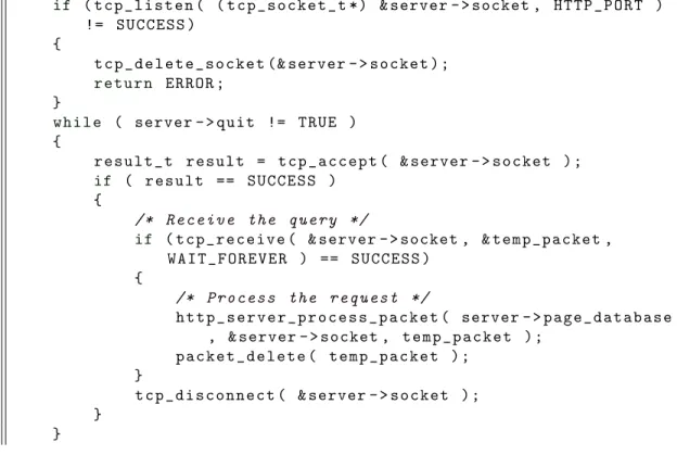
Finally, we initiate embedded HTTP webserver on the module, which contains web pages about configuration mode. Inside a thread function, TCP port number 80 is straightforwardly listened to receive HTTP GET commands. We run the code snippet in Figure 3.8 for http server on the module. Using very simple GUIs and embedded HTTP web server, networks scanned in range by the module are listed to the user as shown in Figure 3.7 and user can connect to any of them from the list by entering the password. After entering a specific SSID and password, the Wi-Fi module switches from Soft AP mode to STA mode. In STA mode, we apply our proposed sleep scheduling scheme explained in the next chapter.
if ( t c p _ l i s t e n ( ( t c p _ s o c k e t _ t *) & server - > socket , H T T P _ P O R T ) != S U C C E S S ) { t c p _ d e l e t e _ s o c k e t (& server - > s o c k e t ) ; r e t u r n E R R O R ; } w h i l e ( server - > qu i t != TR U E ) { r e s u l t _ t r e s u l t = t c p _ a c c e p t ( & server - > s o c k e t ) ; if ( r e s u l t == S U C C E S S ) { /* R e c e i v e the q u e r y */
if ( t c p _ r e c e i v e ( & server - > socket , & t e m p _ p a c k e t , W A I T _ F O R E V E R ) == S U C C E S S )
{
/* P r o c e s s the r e q u e s t */
h t t p _ s e r v e r _ p r o c e s s _ p a c k e t ( server - > p a g e _ d a t a b a s e , & server - > socket , t e m p _ p a c k e t ) ;
p a c k e t _ d e l e t e ( t e m p _ p a c k e t ) ; }
t c p _ d i s c o n n e c t ( & server - > s o c k e t ) ; }
}
Chapter 4
Proposed Long-Term Sleep
Scheduling Scheme
In this chapter we describe our proposed long-term sleep scheduling scheme to reduce energy consumption of home embedded devices connected to a Wi-Fi-based M2M network without losing service availability. Sleep scheduling (or duty cycling) is an effective way to reduce energy consumption in distributed systems and networks [24]. It consists of putting some devices (i.e., their Wi-Fi wire-less modules) into sleep state and alternating between sleep and active states. Most distributed solutions so far aim to ensure coverage while performing sleep scheduling to reduce energy consumption [25], [26]. However, virtually no work considers ensuring device and service availability while doing sleep scheduling.
Our proposed scheme guarantees that at any time at least one station in the home M2M network is active (awake) state. The active station also broad-casts multicast Domain Name Service (mDNS) replies in behalf of stations in sleep state. In this way, we maintain service discovery and availability for all M2M-connected devices, whether in active or sleep state. A monitoring center application, for example, which scans all connected-embedded devices and their offered services, can list all of them although some of the devices are in sleep mode.
Let’s consider a set of appliances as stations S = {ST A1, ST A2, ..., ST AN}
connected to a wireless access point (AP). The aim is to reduce the total energy consumption caused by wireless communication in appliances with the help of sleep scheduling while continuously maintaining service availability for all sta-tions. A station switches between three states: Sleep, Active and Announce. Additionally, we assume that all stations are time synchronized. This can be achieved with a time synchronization protocol, which is out of scope of this the-sis.
The sleeping scheme we propose operates in cycles and in each cycle it puts one device into active state and other devices into sleep state. The states of devices can be updated and changed in each cycle. The cycle duration is a network-wide parameter and needs to be set at network configuration and initialization phase. The time duration during which each device is put into active state contiguously one is called a round. A round consists of multiple cycles. The round duration depends on the number of devices and how many cycles each device stays active contiguously. To give an example, if there are N devices and each device is active for only one cycle time, then the round duration is N cycles.
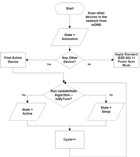
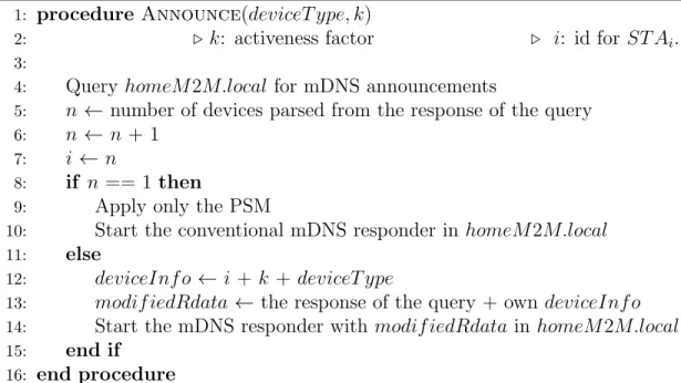
The main state diagram of our sleep scheduling scheme is given in Figure 4.1. When a new device initially joins to a network, it is in Announce state and starts running the Announce algorithm shown in Figure 4.2. According to this algorithm, the new device sends an mDNS query packet to the network and waits for responses. If there is no response, it means there is no other
device in the network except the new one. In this case the new device just
runs the standard IEEE 802.11 power save mode (PSM). Otherwise, the new device discovers and learns about the already existing devices from the mDNS response packets received from them. Meanwhile, the new device also learns which one of these already existing devices is the active device. From the mDNS response received from the active device, the new device also retrieves the current parameters of the sleep-scheduling scheme, which are the current cycle number, the number of devices in the network, and information about other devices in the network (their types and energy levels). Then, the new device informs the active device about itself by injecting an mDNS response packet to the network, which
Figure 4.1: State diagram for an individual device in a home M2M network.
is to be received by the active device.
We propose the use of an activeness factor parameter (k) in our sleeping scheme. Each device has an activeness factor and it indicates how much relative power consumption the device can tolerate at the Wi-Fi module. It is related with the power the device operates with and how the device obtains its energy. This helps balancing the sleep periods among different energy-level devices. If this factor is higher for a device, the device tolerates more to the power consumption at the Wi-Fi module. Otherwise, if this factor is low, the device does not tolerate much in consuming power for wireless communication at the Wi-Fi module. For example, a battery-powered device will have a small activeness factor. As another example, a 1000W appliance will have a larger activeness factor compared to a
1: procedure Announce(deviceT ype, k)
2: ◃ k: activeness factor ◃ i: id for ST Ai.
3:
4: Query homeM 2M.local for mDNS announcements
5: n ← number of devices parsed from the response of the query
6: n ← n + 1
7: i ← n
8: if n == 1 then
9: Apply only the PSM
10: Start the conventional mDNS responder in homeM 2M.local
11: else
12: deviceInf o ← i + k + deviceT ype
13: modif iedRdata ← the response of the query + own deviceInfo
14: Start the mDNS responder with modif iedRdata in homeM 2M.local
15: end if
16: end procedure
Figure 4.2: Announce algorithm.
50W appliance even though both of them are mains-powered. Additionally, limits for standby electric power consumption of home appliances affect activeness factor parameter (k) and these limits are defined by EU’s regulations [27]. For example, the limit for ovens is 1W while the limit for coffee machine is 0.5W. That is, ovens can tolerate more energy consumption compared to coffee machine. Hence, possible activeness factor parameter (k) for ovens will be 2 while it will be 1 for coffee machines.
In our sleeping scheme, the period of time (in cycles) during the which a device stays active in one round depends on the activeness factor of the device. As the activeness factor increases, number of active cycles increases proportionally. Let ki denote the activeness factor for the ST Ai. Using ki values of stations, the
total number of cycles in one round can be calculated as in Equation 4.1. In a round, each ST Ai is active for ki cycles. Then, the number of cycles ti before
the active state of a station ST Ai starts can be calculated with the Equation
4.2. We assume that the Wi-Fi module integrated to an appliance can learn the activeness factor of the device over the serial communication port at power-up or the activeness factor can be pre-configured to the Wi-Fi module attached to the device.
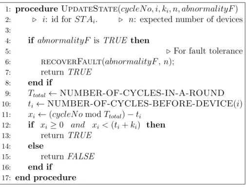
1: procedure UpdateState(cycleNo, i, ki, n, abnormalityF )
2: ◃ i: id for ST Ai. ◃ n: expected number of devices
3:
4: if abnormalityF is TRUE then
5: ◃ For fault tolerance
6: recoverFault(abnormalityF , n);
7: return TRUE
8: end if
9: Ttotal ← NUMBER-OF-CYCLES-IN-A-ROUND
10: ti ← NUMBER-OF-CYCLES-BEFORE-DEVICE(i)
11: xi ← (cycleNo mod Ttotal)− ti
12: if xi ≥ 0 and xi < (ti+ ki) then 13: return TRUE 14: else 15: return FALSE 16: end if 17: end procedure
Figure 4.3: State updating algorithm.
Ttotal = #devices∑ j=1 kj (4.1) ti = i−1 ∑ j=1 kj (4.2)
At the beginning of each cycle, each device runs the algorithm UpdateState given in Figure 4.3 to decide its state in that cycle using the current cycle number, station ID and the Ttotal and ti values given in Equation 4.1 and Equation 4.2. If
the algorithm returns TRUE, the state of the device will be Active. Otherwise, it goes into Sleep state by deactivating its WLAN interface. Each active device retrieves the details of the other devices in the home M2M network and the value of abnormalityF lag from an active device of the previous cycle. Abnormality flag indicates if there was an abnormal condition detected in the previous cycle. When the active device cannot communicate with any active device from the previous cycle, it sets abnormalityF lag to TRUE and it remains active during the subsequent cycles until a stable state. That is, each device runs the algorithm RecoverFault shown in Figure 4.4 at the beginning of each cycle in case of any
1: procedure RecoverFault(abnormalityF, n)
2: Query for mDNS announcements of the appliances
3: ncurrentactive← number of responses to the query
4: if n == ncurrentactive then
5: Set abnormalityF to FALSE;
6: else
7: n← ncurrentactive
8: end if
9: end procedure
Figure 4.4: Fault tolerance algorithm.
crash, and no sleep procedure is applied until all devices are active. After such a stable point, the parameters of the proposed sleep scheduling are reinitialized and the procedure is restarted.
Figure 4.5 indicates how to run the proposed scheduling algorithm in a home M2M network of four stations. In the example, the activeness factor of station 2 (k2) is 3 and other stations have the same activeness factor of 1. The example
illustrates one round, which includes 6 cycles (i.e., Ttotal is 6).
Figure 4.5: A sample scheduling of sleep states by the proposed algorithm for nodes in a home M2M network.
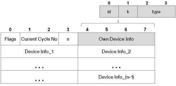
Our sleep scheduling scheme utilizes mDNS query and response packets. We use the Rdata field of mDNS response packets to convey information about sta-tions and their sleep-scheduling related parameters. The format of an mDNS
packet and how we use it to convey information required by our protocol is shown in Figure 4.6. Each mDNS response packet mainly includes algorithm-related flags, current cycle number, number of devices and information about all devices in the network. The flags field is one byte long and the least significant bit is used to indicate abnormality condition, which is set in case of a crash. Other bits in the flags field are reserved. Current cycle number is regularly incremented by one for each cycle. The remaining part of the frame consists of description information of all n devices in the network. Description information for each device is represented with four bytes. Of these four bytes, one byte is used for device identifier (ID), one byte is used for activeness factor of the device (k), and the other two bytes are used for device type. Device IDs are dynamically and incrementally distributed as shown in the Announce algorithm shown in Figure 4.2. Example for device types are given in Table 4.1. Types can be varied and increased depending on use cases.
Figure 4.6: Rdata frame which conveys all sleep-scheduling related parameters encapsulated in mDNS response packet.
All mDNS queries are sent using a service name. The specific service name we use is: homeM2M.local.
In summary, our proposed scheme puts some Wi-Fi modules into sleep mode by guaranteeing that at any time at least one module is active. Since the ac-tive station announces mDNS replies in behalf of stations in sleep mode, our
Table 4.1: Sample usage of device types.
Appliance Device Type
Refrigerator 1 Oven 2 Washer 3 Dryer 4 Dishwasher 5 Tea Machine 6 Coffee Machine 7
proposed approach ensures device and service availability while performing sleep scheduling. We also favor low energy devices by putting them into sleep mode longer. Additionally, all sleep-scheduling related parameters are encapsulated in-side mDNS packets. As will be shown in the next chapter, the proposed sleep scheduling algorithm significantly reduces the energy consumption of Wi-Fi mod-ules in home M2M networks.
Chapter 5
Experiments and Evaluation
In this chapter, we present our experimental results to evaluate the energy con-sumption and efficiency of PSM mode and our sleep scheduling scheme. We first performed experiments and measurements using our M2M test-bed based on our prototype implementation. We measured the energy consumption of Wi-Fi modules using both PSM mode and our sleeping scheme. Then, to evaluate the scalability of our proposed scheme, we did simulation experiments. We used the real energy-consumption data from our test-bed experiments while computing the energy consumption in our simulation experiments.
5.1
Testbed Experiments
To analyze the impact of the standard IEEE 802.11 PSM mode on energy saving and to evaluate the performance of our proposed scheme, we did experiments on our test-bed using our implementation of Wi-Fi device integration.
In our test-bed, as wireless M2M module, we used WICED Wi-Fi module, which consists of a BCM43362 Wi-Fi chip and an STM32F205 microprocessor. The power supply to the module is 3.3V. Broadcom’s WICED Development Sys-tem is a low-power SOC sysSys-tem with a built-in Wi-Fi protocol stack, which
includes a serial communication hardware and a serial driver interface [28]. As long as an embedded device (home appliance) has a serial communication inter-face, the module can be integrated into it easily. It supports 802.11 b, g, n with a maximum rate of 54 Mbps. It also supports TCP and UDP data transmission. Once integrated to an embedded device, the wireless module can be used to con-nect the device to an M2M network, transport data, and perform control and management operations.
Figure 5.1: Current consumption in IEEE 802.11 power save mode. In our test-bed, we first verified, tested and measured the energy efficiency of the standard IEEE 802.11 PSM mode. The experiment result is shown in Figure 5.1. Figure 5.1 is a 5 second capture of electrical current consumed at Wi-Fi module while running an embedded test application that is sending ICMP ping packets to a wireless AP at 1-second intervals. Transmission of ping packets simulates data packets that can be carried in a home M2M network. We set the ping packet size to 64 bytes to mimic the data size in a typical M2M scenario, which is expected to be quite small. In Figure 5.1, the large blue spikes correspond to current consumption in Wi-Fi module while transmitting ping packets. The smaller blue spikes occurring approximately every 300ms correspond to current consumption while Wi-Fi is not transmitting but is awake to listen to the AP to receive a DTIM. A 300ms interval between two blue spikes is the sleep period
between two active states in IEEE 802.11 power save mode. The red spikes that occur at regular 100ms intervals are the result of an IGMP timer in the network stack that wakes the STM32. While verifying the correct operation of the PSM mode, this experimental measurement also reveals the significant energy saving in PSM mode. 70mA would be constantly consumed by listening to the AP instead of waking up from the sleep state periodically for listening traffic announcements. Hence, the current consumption in the Wi-Fi module is much smaller when the module is in PSM mode compared to the listen state.
As current measurement circuit, Maxim MAX4376 current-sense amplifier is used, which measures the differential voltage across a 0.2Ohm resistor in series with the module power supply. Output voltage of the circuit is scaled to produce 1V for every 100mA (or 10V for every 1A) of current consumed. For example, when the Wi-Fi module consumes 500mA, the circuit produces outputs voltage of 5V.
We then measured the effect of our proposed sleep scheduling scheme on energy consumption and efficiency. We first prepared three different test setups with different configuration parameters. In all of these configurations, there is a wireless access point (AP) and multiple embedded devices (boards) representing
home appliances. The appliances connect and send ping packets to the AP.
Additionally, all appliances have equal activeness factor k for these initial tests. In each setup, current consumption in a 40s interval is observed and total energy consumption is calculated by multiplying the power supply voltage (3.3V) with the total area under the current-time curve.
Test-I with the Configuration-I is aimed to observe the total energy consump-tion of the initial infrastructure. In the initial infrastructure, appliances were connected to the home WLAN and neither IEEE 802.11 PSM mode nor our sleep scheduling is applied (the wireless module is fully powered without PSM and without our sleep scheme). Energy consumption during the experiment is shown in Figure 5.2. Total energy consumption for an individual device during the experiment period is measured to be 11.5 Joule.
Figure 5.2: Energy consumption without the PSM mode.
consumption when PSM is used alone. In this experiment, an appliance is firstly associated to the home WLAN and the IEEE 802.11 PSM mode is activated. That is, the Wi-Fi module of an appliance periodically wakes up to listen to the AP. The experiment lasts 40 seconds and at each 5s interval the wireless module sends a ping packet to the AP. The total energy consumption is measured as in Test-I. Total energy consumption for an individual device during the experiment is measured about 5.3 Joule. We also observed that reply time of ping packets is about 0.5s. The delay is caused by the trade-off between energy consumption and packet delay. This measurement obviously concludes that IEEE 802.11 PSM mode provides about 54% energy saving with tolerable delays compared to not using any sleep mode.
In Test-III with the Configuration-III, our proposed sleep scheduling method applied on top of the standard IEEE 802.11 PSM mode is evaluated. That means while the standard PSM is applied, our method is putting the devices into longer sleep modes according to its own scheduler, independent of PSM, and leaves only one device active to maintain continuous service availability in the M2M network. In this setup we connected 3 appliances to the home AP and the maximum sleep
Figure 5.3: Energy consumption with our proposed scheme.
duration for a device is set to 20s. As soon as an appliance connects to the AP, it informs the active device about itself. Then it de-activates its Wi-Fi interface and goes into long sleep until the next cycle. When a device is in deep-long sleep, the active device in the network broadcasts mDNS messages on behalf of the sleeping device and stores the incoming messages destined to it. In this way, an M2M application scanning the available devices in the home network can learn about the existence of sleeping devices from the mDNS reply packets sent by the active device. We calculate the total energy consumption of a device as in Test-I and Test-II. In this Test-III, we measure and calculate the total energy consumption for a device as 4.5 Joule, as shown in Figure 5.3.
Then, in Test-III configuration, we varied the sleep period of devices between 2s and 20s and observed the impact of sleep cycle time on energy saving. Similar to previous experiments, each test lasts 40s and total energy consumption is measured and calculated at the end of each experiment as before. As sleep period decreases, the number of alterations between sleep and active states increases, and each alteration causes energy and delay. Since increasing number of the alterations and the time spent in active state cause more energy consumption, deep sleep scheduling with smaller periods is not energy efficient. As can be seen
0 10 20 30 40 4
5 6 7
Total sleep time (seconds)
Energy
(J)
Deep Sleep with Scheduling Only PSM
Figure 5.4: Energy consumption comparison between the PSM mode and our sleep scheduling applied with different sleep periods.
in Figure 5.4, using only the PSM mode is more advantageous if the proposed sleep scheme is applied with a total sleep period which is smaller than 10s.
As shown in Table 5.1, the proposed scheme achieves energy conservation of up to 61% than the standard mode operation without any sleep scheduling. While this has a huge influence on energy saving, at the same time all devices are discoverable. Our test results validate that our proposed approach strongly reduces Wi-Fi energy consumption and it copes with the crucial drawback of Wi-Fi to play a more significant role in home M2M networks.
Table 5.1: Comparison of energy consumption values for a device while tcycle is
5s and number of devices is 5 in the network.
Test Case Energy Cons. Avg. Pow. Cons. Saving(%)
No sleep mechanism 11.5J 0.3W
-IEEE 802.11 PSM 5.3J 0.14W 54%
5.2
Simulation Experiments
To evaluate the scalability of our proposed approach with larger number of sta-tions, we also did some simulation experiments using the real energy-consumption data from our previous test-bed experiments. We consider a network with n sta-tions connected to an AP and the cycle time for a device is tcycle.
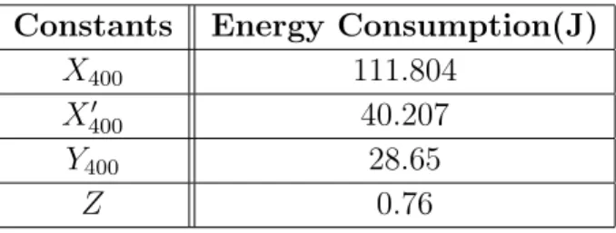
We first want to formulate the energy consumption of a network in different energy saving states. For this we first introduce some notation. Let XT denote
the total energy consumed at a Wi-Fi module during a period of time T when no sleep scheme is applied. XT′ denotes the total energy consumption on a Wi-Fi module during a period of time T when IEEE 802.11 PSM is applied alone. Let YT denote the total energy consumed at a Wi-Fi module during a period of time
T when the module is continuously in deep-sleep state. Finally, Z indicates the total energy consumed at a Wi-Fi module during a transition from sleep state
to active state. The Table 5.2 summarizes all these parameters. These are
calculated from the direct measurement data by applying the methodology used in Section 5.1. For T = 400s, these values are shown in Table 5.3.
Table 5.2: Notation.
Notation Meaning
XT Energy consumption of a device whose state is active during all T -time
XT′ Energy consumption of a device whose state is the PSM during all T -time YT Energy consumption of a device whose state is sleep during all T -time
Z Energy consumption of a device while switching from sleep to active state
ki Activeness factor of ST Ai
m Total number of cycles
n Total number of devices
We will now formulate the energy consumption of three schemes:
• No sleep scheme applied • The 802.11 PSM applied alone
Table 5.3: Energy consumption values used in formula for T = 400 seconds.
Constants Energy Consumption(J)
X400 111.804
X400′ 40.207
Y400 28.65
Z 0.76
The Equation 5.1 approximates Ctotal which is the total energy consumption
of all n stations in the case there is no sleep-scheduling mechanism applied. The Equation 5.2 approximates the total energy consumed by all stations in the case only PSM mode is used, which is denoted with Ctotal′ .
When we, on the other hand, apply our proposed sleep scheme, the total energy consumption of all stations during T second total time interval can be formulated in Equation 5.3 and is denoted with Ctotal′′ . Ctotal′′ comprises three com-ponents, which are total energy consumption in active modes, the total energy consumption in sleep modes and total energy loss caused by transitions between sleep and active modes. As the first component, total energy consumption in active modes of all stations during T second is equal to total energy consumption of a device, which is active during all T second in our proposed scheme. This is because there is only one active device in each cycle and we can think that there is only one active device during all cycles to compute cumulative energy consumption of all n stations in active modes. Second, total energy consumption in sleep modes of all n stations during all cycles is equal to total energy con-sumption of( n− 1) stations, which are in sleep mode during all cycles. This is because all devices except one active device are in sleep mode during one cycle in our proposed approach. As a third component, total energy consumption due to transitions between sleep and active mode is computed by the number of the transitions. Finally, the sum of these three components constitutes Ctotal′′ .
Ctotal ≈ n ∗ XT (5.1)
Ctotal′′ ≈ XT′ + (n− 1) ∗ YT + n ∑#devices j=1 kj ∗ m ∗ Z (5.3) m = T tcycle (5.4)
After formulating energy consumption, we did simulation experiments. First, four test cases with n = 5, n = 7, n = 10 and n = 20 are simulated to observe the effect of activeness factor (k) on energy saving. In each configuration, the activeness factor is assigned a value between 1 and 3. In this case, sum of active-ness factors for all devices is between n and 3n. Energy consumptions of these configurations during a 400s time interval are approximately calculated using the direct measurement values in Table 5.3 and the Equations 5.2 and 5.3. Using the same methodology, we calculate the energy consumption of the case in which only PSM is applied. The results are illustrated in Figure 5.5. They show that as the sum of activeness factors increases, the energy efficiency of our proposed scheme compared to the conventional PSM mode increases as well. While active-ness factors increase, the total number of active and sleep cycles does not change for n stations at the end of all cycles. However, the number of transitions between active and sleep states decreases and consequently the energy consumption due to transitions from sleep to active state is reduced. In other words, keeping some devices more active and favoring low energy devices by putting them into sleep mode longer improve energy efficiency obtained by our proposed approach.
Secondly, to analyze the influence of duty-cycle time on energy efficiency, we vary the cycle time (tcycle) from 1s to 20s in our simulations. The number of
devices in the network is fixed to 8. This is a reasonable assumption for a home network. The activeness factor (k) is assigned in a uniform random manner to devices and the sum of activeness factors is set to be 2n. Energy consumption of our scheme is calculated using the same methodology in the previous simulation experiments. To compare, we also calculate the energy consumption when just PSM is used and when no sleep scheduling is used. As shown in Figure 5.6, our proposed approach outperforms the conventional PSM for duty-cycles greater than 3 seconds. The proposed approach is, however, not very efficient for smaller cycle times. This is because the number of transitions between active and sleep states increases and this change causes a dramatic increase in energy consumption
4 6 8 10 12 14 16 190
195 200
Sum of activeness f actors among 5 devices
T otal energy cons. of all devices(J) Proposed Scheduling Only PSM 6 8 10 12 14 16 18 250 260 270 280
Sum of activeness f actors among 7 devices Proposed Scheduling Only PSM 10 12 14 16 18 20 340 360 380 400
Sum of activeness f actors among 10 devices
T otal energy cons. of all devices(J) Proposed Scheduling Only PSM 20 25 30 35 40 650 700 750 800
Sum of activeness f actors among 20 devices Proposed Scheduling
Only PSM
for very small duty-cycles.
0 5 10 15 20
400 600 800
tcycle- duty cycle time(s)
T otal energy cons. of all devices(J) Proposed Scheduling Only PSM No Sleep
Figure 5.6: The evaluation of various duty cycles.
Thirdly, to study the scalability of our proposed approach, the total energy consumed in a larger network is calculated using the same methodology. We performed simulation experiments with different number of devices from 5 to 15, while assigned activeness factors uniformly and setting tcycleto 10 seconds. Energy
consumption with PSM and no-sleep mechanism is for comparison. Figure 5.7 and Table 5.4 show the results. As the number of devices increases, the energy efficiency of our proposed approach compared to other two cases increases as well. The results obviously reveal that the proposed scheme achieves energy savings up to 71% compared to the standard infrastructure and up to 20% compared to the standard PSM mode. Additionally, device discoverability and availability are preserved. The test results with 15 devices also validate the scalability of the proposed approach. For a home network with small number of devices (e.g., n = 2), however, using only PSM mode can be more beneficial instead of our proposed approach, although the proposed scheme still provides energy saving compared to no-sleep case. The reason for this is that energy-consumption caused by excessive number of transitions between sleep and active state dominates the energy savings achieved by our sleep scheduling.
Table 5.4: Comparision between proposed approach and the other cases for dif-ferent n-devices in terms of energy efficiency.
n Saving compared to ’No Sleep’(%) Saving compared to PSM(%)
5 64.44 1.12 6 66.09 5.73 7 67.28 9.01 8 68.16 11.48 9 68.85 13.40 10 69.40 14.93 11 69.86 16.19 15 71.06 19.53
Finally, we simulate a home M2M network which consists of 6 connected appliances: two refrigerators, one oven, one washer, one dryer and one coffee machine. According to standby electric power consumption of electrical and elec-tronic household appliances defined in the regulation [27], the power consumption of an equipment in any condition providing only a reactivation function shall not exceed 0.5W while the power consumption of equipment with a combination of reactivation function and information display shall not exceed 1W. Therefore, the limit for oven, washer and dryer is 1W, since oven, washer and dryer may have a display to show the clock in addition to buttons for reactivation function. However, the limit for coffee machine is 0.5W, because it only has reactivation function in the standby mode. Based on these constraints, we assigned active-ness factors to these appliances as shown in the Table 5.5. We set the cycle time (tcycle) to 5s, 10s, and 20s in different experiments. Using the same methodology
with previous simulations, total energy consumption for this scenario during a 400s time interval are approximately calculated for our proposed sleep schedul-ing, PSM, and no-sleep case. As shown in Figure 5.8, our proposed approach outperforms the conventional infrastructure with 802.11 PSM mode.
All these simulation results support the conclusion we drew from our testbed experiments that our proposed approach significantly reduces energy consumption in embedded home devices due to Wi-Fi module. In this manner, our proposal
4 6 8 10 12 14 16 500 1,000 1,500 n- number of devices T otal energy cons.(J) Proposed Scheduling Only PSM No Sleep
Figure 5.7: The effect of number of devices.
Table 5.5: The activeness factor (k)s assigned to appliances.
Appliance Activeness factor (k) Limit for standby power cons.
Refrigerator 3 none
Oven 2 1W
Washer 2 1W
Dryer 2 1W
Coffee Machine 1 0.5W
helps in coping with the crucial drawback of Wi-Fi in terms of energy consumption when used in home M2M networks.
5 10 20 200 210 220 230 240 tcycle (seconds) T otal Energy Cons. (J) Proposed Approach PSM