(2019) 43: 264 – 271 © TÜBİTAK
doi:10.3906/fiz-1812-21 h t t p : / / j o u r n a l s . t u b i t a k . g o v . t r / p h y s i c s /
Research Article
Comparison of geometric and drive-induced nonlinearities in doubly clamped,
thermoelastic nanoelectromechanical systems
Mehmet Selim HANAY∗,
Department of Mechanical Engineering, Faculty of Engineering, Bilkent University, Ankara, Turkey
Received: 24.12.2018 • Accepted/Published Online: 08.04.2019 • Final Version: 12.06.2019
Abstract: The performance of resonant sensors based on nanoelectromechanical systems depends critically on the
maximum amplitude of oscillation reached in the linear regime. The maximum linear amplitude is determined by nonlinear mechanisms that can originate from the material, geometric and transduction mechanism related factors. Here we compare the two competing effects, the geometric and drive-induced nonlinearities, for a commonly used device family, the thermoelastically driven, doubly clamped beams. We find that the geometric nonlinearity dominates for most of the device designs used in the literature, however the drive-induced nonlinearity becomes the determining factor for thicker beams with small electrode lengths.
Key words: Nanoelectromechanical systems, nonlinearity, mass sensing, Duffing nonlinearity
1. Introduction
Nanoelectromechanical systems (NEMS) have emerged in the last two decades as sensitive detectors of force [1,2] and mass measurements [3−6]. By decreasing the dimensions of mechanical sensors, it is possible to analyze different gases at the parts-per-billion concentration level [7,8], and detect single nanoparticles and biomolecules one-by-one [9]. Such functionality provides an alternate way for performing mass spectrometric identification of chemical species, entirely based on inertial measurements [3,9].
One of the limiting effects in mass sensing is the finite value of linear dynamic range of the sensor. The linear dynamic range is defined as the ratio of the maximum vibration amplitude of the structure in the linear regime to the minimum resolvable vibration amplitude (which is determined by the measurement noise floor). As shown in [10], larger dynamic range implies better sensor resolution. Therefore, it is important to understand [11,12] and optimize [13] different mechanism, which can limit the dynamic range of NEMS sensors. Here, we consider one of the emerging NEMS device concept, the thermoelastically driven NEMS, and compare the two competing effects in determining the linear regime of operation: the geometric nonlinearities and the effect of driving the NEMS by the thermoelastic transduction.
Thermoelastically driven NEMS have been first developed to drive the multiple modes of a nanomechan-ical structure simultaneously [14]. This device family was later used for the two-mode experiments to weigh single proteins in real time [9], and continues to be a potent platform for performing multimode dynamical experiments [15] and quality factor studies [16]. For this reason, charting the linear regime of operation is important for this device family. Among the three possible sources of nonlinearity, material nonlinearity is
∗Correspondence: [email protected]
not considered here, since the common materials used in NEMS fabrication display a linear behaviour unless very large strains are reached. The geometric nonlinear effects emerge from the increased tension on the beam due to vibrations: this effect can be modelled in the equation of motion by the inclusion of a Duffing term, third-order in the displacement [12]. The drive-induced nonlinearity arises from the change of resistance at large deformations in the metallic electrode used to drive the mechanical motion. The form of nonlinearity in this case is a hardening nonlinearity, unlike the softening nonlinearity observed in electrostatically driven mechanical structures [17].
In the following, we will describe general device operation in more detail, calculate the relative strength of the geometric and drive-induced nonlinearities, and chart the boundary in the design space between the two regions.
2. Materials and methods
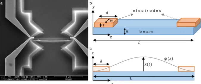
A NEMS resonator is shown in Figure 1a, which is considered to be a generic example of a thermo-elastically driven, doubly clamped beam structure considered here. The device consists of a structural material that forms the doubly clamped beams, and a metallic electrode layer on each side to drive and detect the motion electronically. In the particular case of Figure 1, the structural material is silicon nitride and the metal used in electrodes is gold. The fabrication of the device is detailed previously in [15]. In summary, it consists of three electron beam lithography steps, followed by gold depositions in the first two steps for metallic interconnects, and by copper deposition in the final one as the etch mask. The NEMS is released by using a plasma etcher performing first an anisotropic etching recipe, and then an isotropic etching recipe. Copper mask layer is removed by a metallic etchant. Suspended devices are then wired to printed circuit boards (PCBs) for electronic characterization. For the typical device shown in Figure 1, the dimensions are 7 µ m in length, 100 nm in thickness, and 320 nm in width.
Figure 1. a. A NEMS device in the form of a doubly clamped beam. The device is composed of silicon nitride. Gold
electrodes on the left and right edges of the beam are used for driving and detecting the motion. b. Device and electrode parameters are indicated on the figure. (The electrodes are drawn and modeled as rectangular prisms for simplicity.) c. The mode shape ϕ(z) shows the oscillation amount of the different portions of the beam. The amplitude of the center of the beam, x(t) , is treated as the main degree of freedom through this study.
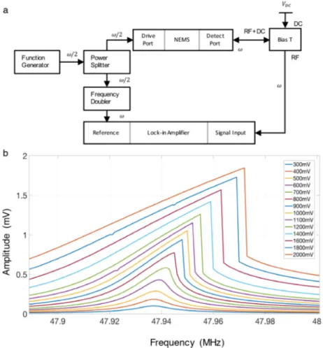
The device can be driven to its resonance by applying an AC voltage at half of the mechanical resonance frequency (Figure 2a). The readout is achieved by probing the dynamic piezoresistance change on the other electrode [14]. The readout voltage levels are adjusted so that they are at least smaller by a factor of two than the drive voltage levels. For this reason, we do not expect the readout part to significantly affect the dynamics of the device. As the input drive power is increased, the amplitude of the device increases first in the linear region, and then transitions into the nonlinear regime which is characterized by a sharp downward jump in the motion amplitude when sweeping the frequency from left to right (Figure 2b).
Figure 2. a. Measurement circuit for typical resonance detection experiments. The frequency of the signal between
different components is also shown (NEMS frequency ω , or its half ω/2) b. Amplitude vs. frequency curve for the response of the NEMS device. As the drive power increases, the device starts to exhibit nonlinear response in the form of sudden downward jumps. The frequency sweep direction is left to right.
3. Results
We now start analyzing the two forms of nonlinearity by considering the two sources of nonlinearity: the geometric (Duffing) nonlinearity and the drive-induced nonlinearity. The equation of motion for a doubly clamped beam with tension-induced Duffing nonlinearity can be written as:
¨ x +ωn Q x + ω˙ 2 nx + α x 3=F (x) ρLA (1)
where ρ is the density, ωn≡ √
k
m is the natural resonance frequency, Q is the Quality Factor, A is the cross-section, and L is the length of the beam. In the equation above, the Duffing coefficient ( α), which determines the strength of geometrical nonlinearity is given as [12]:
α = E 2ρL [∫z=L z=0 ( ϕ′ )2 dz ]2 ∫z=L z=0 ϕ2dz (2)
where z is the axial direction of the beam and ϕ = ϕ(z) denotes the mode shape (normalized such that the maximum value is 1). Figure 1c shows the fundamental mode shape of a doubly clamped-beam. The derivative ϕ′ is taken with respect to the z coordinate: ϕ′ = ∂ϕ /∂z and originates from the elongation of the beam under flexural oscillation. The integrals in Eq. (2) are calculated through the entire length of the device, L , as shown in Figure 1c.
The driving force is generated due to the thermal stress mismatch between the gold electrodes and the underlying silicon nitride beam. The Joule heating at the electrode increases the local temperature, which induces expansion. The expansion coefficients of the materials in the bilayer structure are different and this difference causes a local stress. The force generated due to thermoelastic effect can be expressed as:
F = gV
2
R (3)
where V is the applied voltage on the electrode, R is the resistance of the electrode, and g is the conversion factor between the heat dissipated on the beam and the resulting thermoelastic force ( F ) [14]. As long as the assumptions of linear elasticity hold (i.e. the compliance stays in the linear region), then the conversion factor between the heats to force stays constant. To calculate the nonlinearity in the driving force, we consider the changes in the resistance of the metallic loop due to the extension of the electrode itself as the structures oscillate. To calculate the change in resistance, we first observe that a metallic electrode is used in the experiments so that the piezoresistance is determined by geometrical changes [18]. The resistance of the electrode can be written as:
R = ρe d
wt (4)
where ρe is the resistivity, d is the length, w is the width, and t is the thickness of the electrode. As the beam displaces by an amount x , it deforms the resistor:
d→ d(1 + ϵ (x)) w→ w(1 − ν ϵ (x))
t→ t(1 − ν ϵ (x))
where ϵ (x) shows the average strain caused by the modal displacement x , and ν denotes the Poisson’s ratio. Therefore, the resistance due to beam deflection can be written as:
To calculate the average strain ϵ (x), we consider a deformed section of the beam and calculate the square of the infinitesimal change in length:
ds = dz √
1 + (x ϕ′)2
We can then apply Taylor expansion on the square root and keep the first two terms, since x ϕ′ ∼ x
Lϕ , where the ratio of the oscillation amplitude over the length of the beam is much smaller than 1, and ϕ is at most 1. Thus: ds = dz ( 1 + 1 2 ( x ϕ′ )2)
Therefore, the change in the length of the electrode, d , can be written as:
∆d = 1 2x 2 ∫ z=d z=0 ( ϕ′ )2 dz
We note that this time the integral is taken over the electrode (Figure 1c) as we want to calculate its extension. The average strain through the electrode can be calculated as:
ϵ (x) = ∆d d = 1 2dx 2 ∫ z=d z=0 ( ϕ′ )2 dz (6)
By plugging this form on the resistance change we obtain:
R = R0 ( 1 + 1 + 2ν 2d x 2 ∫ z=d z=0 ( ϕ′ )2 dz )
Then the equation of motion (Eq. (1)) with the nonlinear force term becomes:
¨ x + ωn Q x + ω˙ 2 nx + α x 3= 1 ρLAF0 ( 1 +1 + 2ν d x 2 ∫ z=d z=0 ( ϕ′ )2 dz )
In this expression, the term α x3 shows the geometric nonlinearity, whereas the term 1+2ν
ρLAdF0x 2∫z=d z=0 ( ϕ′ )2 dz corresponds to the nonlinearity due to thermoelastic transduction. By comparing their relative strength, Γ :
Γ = geometric nonlin. contr. transduction nonlin. contr. =
αx3 1 ρLAF0 (1+2ν d ) x2∫z=d z=0 (ϕ ′)2
and using the value of α as in Eq. (2) and rearranging the terms, we obtain:
Γ = Ad (1 + 2ν) Ex F0 1 ∫ ϕ2dz [∫z=L z=0 ( ϕ′ )2 dz ]2 ∫z=d z=0 (ϕ ′)2 dz The expression can be made more transparent by using a change of variable:
ξ = z
so that: Γ = AdE L2 x F0 χ (8)
where χ is a numerical factor on the order of unity. Now, since the resonator works near the resonance, we can approximate: x ∼ Q F0
kef f, where kef f is the effective spring constant and Q is the quality factor of the
resonator. Therefore: Γ = AdE L2 Q kef f χ
For the flexural mode of a doubly clamped beam, the effective spring constant can be written as: kef f ∼EIL3 ∼ EAh2
L3 , where I denotes the moment of inertia and h denotes the thickness of the NEMS beam. Therefore, the ratio between the geometric and drive-induced nonlinearities can be rewritten as:
Γ = dL
h2Qχ (9)
4. Discussion
After obtaining an expression for the relative strength of the two nonlinearities, we now study this expression using different parameters of d, L, h N, and Q. In a typical experimental situation, such as in [15] experiments, d = 780nm (gold electrode width), L = 20µm , h = 100nm , and Q∼ 2 × 10³, we obtain Γ∼ 3 106; therefore,
drive-induced nonlinearities seem to be much smaller compared to geometric nonlinearities. The situation may be reversed for low quality factor sensors, which results in, for instance, the NEMS being operated in air or in liquid. For a generic case of Q = 50 and L = 20 µm we see that:
d
h2 > 1000, (10)
where both d and h are measured in micrometers, gives the region where the drive-induced nonlinearity becomes the limiting factor. This region should be avoided during the design stage, because the dynamical range for NEMS is further limited from its inherent magnitude (set by the geometrical nonlinearity). For a design space of d and h, this region of limited dynamical range indicated in Eq. (10) is depicted in Figure 3. As can be seen from the Figure, the dynamic range gets smaller than its intrinsic value when both the thickness of the device is large and the electrode length is small.
So a design principle emerges from the analysis above to decrease the thickness of the structure while increasing the electrode length. The first rule, decreasing the thickness ( h), is in line with other device considerations to optimize the mass resolution: thinner devices lead to better mass responsivity, since the effective mass of the sensor is decreased. However, the second rule, increasing the electrode length ( d), is not necessarily a straightforward conclusion. This is because, when the electrode length is increased, the effective mass of the sensor also increases, and mass responsivity decreases. Further analysis should be conducted to explore the interplay among the dynamic range, mass responsivity and transducer efficiency as a function of electrode length.
In conclusion, we have theoretically studied and compared the strength of two competing sources of nonlinearity for the thermo-elastically driven, doubly clamped beam devices. The results suggest that, to avoid shrinking the dynamic range, the electrode length should be kept moderately long and the thickness of the NEMS
Figure 3. The scaled ratio between the geometric and drive-induced nonlinearities ( Γ/1000) for Q = 50 and L = 20 µm
in the design space of the device thickness ( h) and electrode length ( d) . The boundary shows where the nonlinear effect due to the thermo-elastic drive surpasses the inherent geometric nonlinearity. DR: Dynamic Range.
as small as possible. While the condition for the device thickness aligns with the mass resolution considerations, the condition for the electrode length provides a trade-off between dynamic range and mass resolution.
Acknowledgments
We thank Cenk Yanık, Mert Yüksel, Atakan B. Arı and Ezgi Orhan for help with NEMS device fabrication and characterization. This work was supported by the Scientific and Technological Research Council of Turkey (TÜBİTAK) project 115E230.
References
[1] Gil-Santos, E.; Ramos, D.; Martinez, J.; Fernandez-Regulez, M.; Garcia, R.; San Paulo, A.; Calleja, M.; Tamayo, J. Nat. Nanotech. 2010, 5, 641-645.
[2] De Lépinay, L. M.; Pigeau, B.; Besga, B.; Vincent, P.; Poncharal, P.; Arcizet, O. Nat. Nanotech. 2017, 12, 156. [3] Naik, A. K.; Hanay, M. S.; Hiebert, W. K.; Feng, X. L.; Roukes, M. L. Nat. Nanotech. 2009, 4, 445-450. [4] Yang, Y. T.; Callegari, C.; Feng, X. L.; Ekinci, K. L.; Roukes, M. L. Nano Lett. 2006, 6, 583-586. [5] Chiu, H. Y.; Hung, P.; Postma, H. W.;Bockrath, M. Nano Lett. 2008, 8, 4342-4346.
[6] Chaste, J.; Eichler, A.; Moser, J.; Ceballos, G.; Rurali, R.; Bachtold, A. Nat. Nanotech. 2012, 7, 301.
[7] Li, M.; Myers, E. B.; Tang, H. X.; Aldridge, S. J.; Mccaig, H. C.; Whiting, J. J.; Simonson, R. J.; Lewis, N. S.; Roukes, M. L. Nano Lett. 2010, 10, 3899-3903.
[8] Bargatin, I.; Myers, E.; Aldridge, J.; Marcoux, C.; Brianceau, P.; Duraffourg, L.; Colinet, E.; Hentz, S.; Andreucci, P.; Roukes, M.L. Nano Lett. 2012, 12, 1269-1274.
[9] Hanay, M. S.; Kelber, S.; Naik, A. K.; Chi, D.; Hentz, S.; Bullard, E. C.; Colinet, E.; Duraffourg, L.; Roukes, M. L. Nat. Nanotech. 2012, 7, 602-608.
[10] Ekinci, K.; Yang, Y.; Roukes, M. J. Appl. Phys. 2004, 95, 2682-2689.
[11] Kozinsky, I.; Postma, H. C.; Kogan, O.; Husain, A.; Roukes, M. L. Phys. Rev. Lett. 2007, 99, 207201.
[12] Lifshitz, R.; Cross, M. In Review of nonlinear dynamics and complexity; Schuster, H.G., Eds. Wiley-VCH: Darm-stadt, Germany, 2008, pp. 1-52.
[13] Kacem, N.; Hentz, S.; Pinto, D.; Reisg, B.; Nguyen, V. Nanotechnology 2009, 20, 275501. [14] Bargatin, I.; Kozinsky, I.; Roukes, M. Appl Phys Lett, 2007, 90, 093116.
[15] Arı, A. B.; Karakan, M. Ç.; Yanık, C.; Kaya, I. I.; Hanay, M. S. Phys. Rev. Appl. 2018, 9, 034024.
[16] Miller, J. M. L.; Zhu, H.; Heinz, D. B.; Chen, Y.; Flader, I. B.; Shin, D. D.; Lee, J. E-Y., Kenny, T. W. Phys. Rev.
Appl. 2018, 10, 044055.
[17] Zhao, J.; Bridges, G.; Thomson, D. J. Vac. Sci. Technol. A. 2006, 24, 732-736. [18] Li, M.; Tang, H. X.; Roukes, M. L. Nat. Nanotech. 2007, 2, 114-120.