Complementary chiral metamaterials with giant optical activity and negative
refractive index
Zhaofeng Li, Kamil Boratay Alici, Evrim Colak, and Ekmel Ozbay
Citation: Appl. Phys. Lett. 98, 161907 (2011); doi: 10.1063/1.3574909 View online: http://dx.doi.org/10.1063/1.3574909
View Table of Contents: http://apl.aip.org/resource/1/APPLAB/v98/i16
Published by the American Institute of Physics.
Related Articles
Electro-optic chirality control in MgO:PPLN
J. Appl. Phys. 112, 073103 (2012)
Understanding of nonlinear optical properties of CS2 from a microscopic viewpoint
J. Chem. Phys. 137, 084315 (2012)
Nuclear spin optical rotation and Faraday effect in gaseous and liquid water
J. Chem. Phys. 136, 184502 (2012)
Preventing optical deactivation of nanocluster Si sensitized Er using nanometer-thin SiNx/SiO2:Er heterolayer thin film
J. Appl. Phys. 108, 073101 (2010)
Colossal optical activity of split-ring resonator arrays for millimeter waves
Appl. Phys. Lett. 97, 081116 (2010)
Additional information on Appl. Phys. Lett.
Journal Homepage: http://apl.aip.org/Journal Information: http://apl.aip.org/about/about_the_journal
Top downloads: http://apl.aip.org/features/most_downloaded
Information for Authors: http://apl.aip.org/authors
Complementary chiral metamaterials with giant optical activity and
negative refractive index
Zhaofeng Li,1,a兲Kamil Boratay Alici,1Evrim Colak,1and Ekmel Ozbay1,2
1Department of Physics, Nanotechnology Research Center, Bilkent University, Bilkent, 06800 Ankara, Turkey
2Department of Electrical and Electronics Engineering, Bilkent University, Bilkent, 06800 Ankara, Turkey
共Received 1 February 2011; accepted 13 March 2011; published online 20 April 2011兲
A complementary bilayer cross-wire chiral metamaterial is proposed and studied experimentally and numerically. It exhibits giant optical activity and a small circular dichroism. The retrieval results reveal that a negative refractive index is realized for right circularly polarized waves due to the strong chirality. Our numerical results show that the mechanism of the chiral behavior at the resonance of lower frequency can be interpreted as the coupling effects between two sets of mutually twisted virtual magnetic dipoles, while the resonance of higher frequency shows complicated nonlocal features. © 2011 American Institute of Physics.关doi:10.1063/1.3574909兴
Recently, chiral metamaterials 共CMMs兲 have attracted much attention due to their exotic properties, e.g., giant op-tical activity, circular dichroism, and negative refraction.1–13 A CMM lacks any mirror symmetry so that the cross-coupling between the electric and magnetic fields exists at the resonance. The degeneracy of the two circularly polar-ized waves is thereby broken, i.e., the refractive indices of right circularly polarized共RCP, +兲 waves and left circularly polarized共LCP, ⫺兲 waves have different values. The strength of the cross-coupling effect can be described by a chirality parameter, so that the constitutive relations of a chiral me-dium is given by
冉
D B冊
=冉
0 − i/c i/c 0冊冉
E H冊
, 共1兲where 0 and 0 are the permittivity and permeability of
vacuum. andare the relative permittivity and permeabil-ity of the chiral medium. c is the speed of light in vacuum. Assuming a time dependence of e−it, the RCP共+兲 wave and LCP共⫺兲 wave are defined as E⫾=共1/2兲E0共xˆ⫿iyˆ兲 when the
waves are propagating in the positive z direction.14 The re-fractive indices for RCP and LCP waves can be expressed as
n⫾= n⫾,15 where n =
冑
. When is large enough, eithern+or n−becomes negative. At the same time, both RCP and
LCP waves have the same impedance of z/z0=
冑
/, wherez0 is the impedance of the vacuum.
Now, consider two structures as shown in Figs.1共a兲and
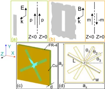
1共b兲, in which one structure is a short thin metal wire, and the other is its complement, i.e., a slot cut in an infinite planar metal sheet. According to Babinet’s principle, if the metal wire is normally illuminated from z⬍0 by an incident field共E0, B0兲 and its complementary screen is illuminated by
a complementary incident field共Ec0= −cB0, B
c
0= E0/c兲, then
the pattern of the field scattered by the metal wire is the same as that which is scattered by its complement except that the polarization of the fields will be opposite for the two sys-tems. Since the field scattered by the wire can be approxi-mated as the radiation field by an electric dipole when the higher order multipolar fields are negligible, the field
scat-tered by its complement can then be thought of as the radia-tion field produced by a virtual magnetic dipole. The electric 共magnetic兲 dipoles on the z⬍0 and z⬎0 sides are symmetric 共antisymmetric兲 in order to fulfill the boundary conditions,14,16as shown in the insets of Figs.1共a兲and1共b兲. Babinet’s principle has been applied to the design of meta-surfaces and single-layered metamaterials.16–18 However, it is rarely seen that this principle is used to construct multi-layered metamaterials. In this letter, we propose a design of a complementary CMM 共CCMM兲 based on the complemen-tary structure of the bilayer cross-wire CMM reported before.10,12
Figure1共c兲shows the schematic of one periodic unit cell of the CCMMs which consists of double layered metal 共cop-per兲 plates patterned on opposite sides of an FR-4 board. Two cross-wires that are mutually twisted by 30° are cut out from the two metal plates. The relative dielectric constant of
a兲Electronic mail: [email protected].
Z<0 Z>0
m
-m
B
k
(c)
(d)
(b)
E
k
Z<0
p
p
Z>0
(a)
FIG. 1. 共Color online兲 Illustration of the scattering behavior of a short thin metal wire共a兲 and its complimentary structure 共b兲 when they are illuminated by an external field from z⬍0 according to Babinet’s principle. 共c兲 Sche-matic of a unit cell of the complementary cross-wire pair metamaterial.共d兲 The structure viewed from front. The parameters are given by ax= ay = 21 mm, d = 1.6 mm, w = 1.6 mm, L = 20 mm, and 1=2=3= 30°. The
copper has a thickness of 0.03 mm. APPLIED PHYSICS LETTERS 98, 161907共2011兲
0003-6951/2011/98共16兲/161907/3/$30.00 98, 161907-1 © 2011 American Institute of Physics
the FR-4 board is 4.0 with a dielectric loss tangent of 0.025. The dimensions of the unit cell are shown in Fig. 1共d兲 and the caption. To study this chiral structure, we conducted nu-merical simulations and experiments. The simulation works were carried out by using CST microwave studio共Computer Simulation Technology GmbH, Germany兲, wherein the finite integration technique was applied. The periodic boundary conditions were applied to the x and y directions, and the absorbing boundary conditions were applied to the z direc-tion. In the experiment, we fabricated the chiral structures with a dimension of 18 by 18 unit cells. The transmission coefficient was measured by an HP-8510C network analyzer with two standard horn antennas. A linearly polarized elec-tromagnetic共EM兲 wave 共E field in the x direction兲 is incident on the chiral structure. On the other side of the structure, we measured the transmitted field in the x and y polarizations 共Txxand Tyx兲. Due to the fourfold rotational symmetry, cir-cular polarization conversion is absent. The transmission of circularly polarized waves can be converted from the linear transmission coefficients Txx and Tyx,
10
T⫾= Txx⫾iTyx. For the transmitted EM wave, the polarization azimuth rotation angle is calculated as=关arg共T+兲−arg共T−兲兴/2, and the
el-lipticity is defined as = arctan关共兩T+兩−兩T−兩兲/共兩T+兩+兩T−兩兲兴,12 which also measures the circular dichroism.
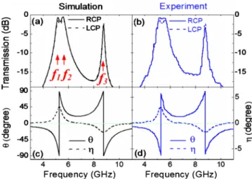
Figures2共a兲and2共b兲show the simulated and measured transmission spectra. The transmissions of RCP and LCP waves are almost the same except for a little difference共1–2 dB兲 around the three transmission peaks, i.e., f1= 5.17 GHz,
f2= 5.58 GHz, and f3= 8.77 GHz, respectively. Figures2共c兲
and2共d兲show the results ofandof the transmitted wave. It can be clearly seen that the ellipticity is less than 3° within the whole frequency range. This is almost one order of magnitude smaller than that reported earlier for the four-U-SRRs CMMs 共Ref. 13兲 which used the same lossy FR-4
board but had larger than 20° at resonances. At the fre-quency f = 6.9 GHz, = 0 where it corresponds to a pure optical activity effect, i.e., for the linearly polarized incident wave, the transmission wave is still linearly polarized but with a rotated angle . The azimuth rotation angle is ap-proximately 20° at 6.9 GHz, which is more than 500° per wavelength.
Figure3 shows the retrieved effective parameters based on the simulation and experimental data of the transmission and reflection for one layer of the CCMMs.19 Here, the ef-fective thickness of the CMM is assumed to be 3.0 mm along the wave propagation direction. On the curves shown in Figs. 3共a兲 and3共b兲, there are two resonances related to the chirality. The lower frequency resonance happens at f = 5.28 GHz, and the upper one happens at f = 8.77 GHz. Be-low f = 5.28 GHz, n is positive while is negative. Above this frequency n is negative and is positive. For f = 8.77 GHz, onlychanges its sign while n remains positive on both sides. Comparing Figs.3共a兲and3共b兲with Figs.3共c兲 and3共d兲, due to the relation of n⫾= n⫾, the strong chirality has pushed the refractive index of the RCP wave from positive to negative values below f = 5.28 GHz and above
f = 8.77 GHz. At the same time, above f = 5.28 GHz, the
originally negative index band of the LCP wave becomes wider. For the RCP wave, the figure of merit 关−Re共n+兲/Im共n+兲兴 is around 5.2 共4.5兲 at 5.16 共8.80兲 GHz in
the negative index band. For the LCP wave, the figure of merit is larger than 15 at 5.3 GHz in the negative index band. These values are higher than that reported earlier.13 In Figs.
3共e兲and3共f兲, we show the retrieved real parts of the and. Obviously, due to the presence of the continuous metal plate, there exists a plasma frequency f = 5.10 GHz below which the Re共兲 is always negative. Corresponding to the two reso-nance frequencies 共5.28 and 8.77 GHz兲 of thecurve, there are two obvious resonances on the curve of Re共兲, and an obvious resonance and a tiny resonance on the curve of Re共兲. Besides the above two resonances, there are two huge resonances on the curve of Re共兲 located at 7.2 GHz and 9.0 GHz, respectively. However, they do not affect the chiral behavior and will not be discussed here. It is noteworthy that in the frequency ranges 5.10–5.28 GHz and 8.77–8.90 GHz, both the Re共兲 and Re共兲 are positive and will not result in a negative index in traditional metamaterials. Therefore, the
FIG. 2. 共Color online兲 Simulation and experimental results for the CCMM. 共a兲 and 共b兲 are the transmission spectra for RCP and LCP waves. f1
= 5.17 GHz, f2= 5.58 GHz, and f3= 8.77 GHz indicate three transmission peaks.共c兲 and 共d兲 are the rotation angleand the ellipticity angleof the transmitted wave.
FIG. 3. 共Color online兲 The retrieved effective parameters of the CCMM based on the simulation共left兲 and experimental 共right兲 data. 共a兲 and 共b兲 show the real parts of the n and.共c兲 and 共d兲 show the real parts of the n+and n−.
共e兲 and 共f兲 show the real parts of the and.
161907-2 Li et al. Appl. Phys. Lett. 98, 161907共2011兲
negative index of RCP wave is actually attributed to the rela-tively small n and large chirality .
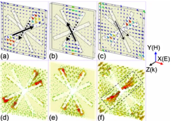
For further understanding the mechanism of the chiral behaviors, we now study the distribution of the H fields on the middle plane between the two metal plates and the sur-face current modes. Figure 4 shows the simulated H field distributions and the current modes at the frequencies of three transmission peaks, e.g., Fig. 4共a兲 and 4共d兲 at f1
= 5.17 GHz, Fig. 4共b兲 and 4共e兲 at f2= 5.58 GHz, and Fig. 4共c兲 and 4共f兲 at f3= 8.77 GHz, respectively. For all three
cases, the incident waves have the E field polarized in the x direction. From Fig. 4共a兲 and 4共d兲, one sees that both the distribution of the H field and the current mode resemble the coupling of a pair of antisymmetrically arranged magnetic dipoles. The two virtual magnetic dipoles are depicted in Fig.
4共a兲, with the thick solid 共dashed兲 arrow representing the front 共back兲 virtual magnetic dipole. The angle is 30° be-tween the two dipoles. For the case of Figs.4共b兲and4共e兲, the distribution of H field and current mode also resemble the coupling of a pair of antisymmetrically arranged magnetic dipoles. The only difference is the angle, which is 60° in this case. However, Figs.4共c兲and4共f兲are complicated. Both the
H field and current mode are not well confined to the slots.
Only the H field on the corners partially resembles the cou-pling of two symmetric magnetic dipoles关thin arrows in Fig.
4共c兲兴, while the main part of the H field in the center region is attributed to the antisymmetric currents as indicated with dashed box in Fig. 4共f兲. These antisymmetric currents func-tion as coupled electric dipoles instead of magnetic dipoles. In all three cases, the net values of the induced H fields are nonzero in the x direction. The causality between E and H fields is consistent with Eq.共1兲. Furthermore, we also inves-tigated numerically the effect of thickness of the middle layer 共d兲 on the transmission and optical activity. When d increases, the coupling between the two metal plates
be-comes weaker so that the optical activity bebe-comes lower and the frequency gap between the transmission peaks f1共f2兲 and
f3decreases.
In summary, we have demonstrated the chiral properties of a CCMM. Like its counterpart共the cross-wire CMM兲, the CCMM also shows giant optical activity, and due to the strong chirality, the frequency bands of negative index are obtained for RCP waves. The mechanism of the chiral be-havior at the resonance of lower frequency can be interpreted as the coupling effects between two sets of mutually twisted virtual magnetic dipoles, but the resonance of higher fre-quency shows complicated nonlocal features which cannot be interpreted simply with a model of virtual magnetic di-poles.
This work is supported by the European Union under the projects PHOME, ECONAM, and N4E, and TUBITAK un-der Project Nos. 109E301, 107A004, and 107A012, and DPT under the project DPT-HAMIT. One of the authors 共E.O.兲 also acknowledges partial support from the Turkish Academy of Sciences.
1J. B. Pendry,Science 306, 1353共2004兲.
2S. Tretyakov, I. Nefedov, A. Sihvola, S. Maslovski, and C. Simovski,J.
Electromagn. Waves Appl. 17, 695共2003兲.
3A. V. Rogacheva, V. A. Fedotov, A. S. Schwanecke, and N. I. Zheludev,
Phys. Rev. Lett. 97, 177401共2006兲.
4H. Liu, D. A. Genov, D. M. Wu, Y. M. Liu, Z. W. Liu, C. Sun, S. N. Zhu,
and X. Zhang,Phys. Rev. B 76, 073101共2007兲.
5T. Q. Li, H. Liu, T. Li, S. M. Wang, F. M. Wang, R. X. Wu, P. Chen, S. N.
Zhu, and X. Zhang,Appl. Phys. Lett. 92, 131111共2008兲.
6N. Liu, H. Liu, S. Zhu, and H. Giessen,Nat. Photonics3, 157共2009兲. 7B. Wang, J. Zhou, T. Koschny, and C. M. Soukoulis,Appl. Phys. Lett. 94,
151112共2009兲.
8S. Zhang, Y.-S. Park, J. Li, X. Lu, W. Zhang, and X. Zhang,Phys. Rev.
Lett. 102, 023901共2009兲.
9E. Plum, J. Zhou, J. Dong, V. A. Fedotov, T. Koschny, C. M. Soukoulis,
and N. I. Zheludev,Phys. Rev. B 79, 035407共2009兲.
10J. Zhou, J. Dong, B. Wang, T. Koschny, M. Kafesaki, and C. M.
Soukou-lis,Phys. Rev. B 79, 121104共R兲 共2009兲.
11M. Decker, M. Ruther, C. E. Kriegler, J. Zhou, C. M. Soukoulis, S.
Lin-den, and M. Wegener,Opt. Lett. 34, 2501共2009兲.
12Z. Li, H. Caglayan, E. Colak, J. Zhou, C. M. Soukoulis, and E. Ozbay,
Opt. Express 18, 5375共2010兲.
13Z. Li, R. Zhao, T. Koschny, M. Kafesaki, K. B. Alici, E. Colak, H.
Cag-layan, E. Ozbay, and C. M. Soukoulis, Appl. Phys. Lett. 97, 081901
共2010兲.
14J. D. Jackson, Classical Electrodynamics, 3rd ed. 共Wiley, New York,
1998兲.
15J. A. Kong, Electromagnetic Wave Theory共EMW, Cambridge, MA, 2008兲. 16F. Falcone, T. Lopetegi, M. A. G. Laso, J. D. Baena, J. Bonache, M.
Beruete, R. Marques, F. Martin, and M. Sorolla, Phys. Rev. Lett. 93,
197401共2004兲.
17T. H. Hand, J. Gollub, S. Sajuyigbe, D. R. Smith, and S. A. Cummer,
Appl. Phys. Lett. 93, 212504共2008兲.
18N. Liu, S. Kaiser, and H. Giessen,Adv. Mater.共Weinheim, Ger.兲 20, 4521
共2008兲.
19R. Zhao, Th. Koschny, E. N. Economou, and C. M. Soukoulis,Phys. Rev.
B 81, 235126共2010兲.
FIG. 4. 共Color online兲 The scattered H field distributions on the middle plane between the two metal plates and the current modes when driven by the incident field with E in the x direction at共a兲 and 共d兲 5.17 GHz, 共b兲 and 共e兲 5.58 GHz, and 共c兲 and 共f兲 8.77 GHz. The long solid 共dashed兲 arrows represent the front共back兲 virtual magnetic dipoles.
161907-3 Li et al. Appl. Phys. Lett. 98, 161907共2011兲