WE2
8:15am
-
8:30amNovel Integrated Optical Displacement Sensor For
Scanning Force Microscopies
Atilla Aydinli,
Isa
K y a t , andCoskun Kocabas
Department of Physics Bilkent University
06800, Ankara, Turkey
Email: aydmliC3fen.bilkent.edu.u
Abslmcf-A novel displacement sensor for scanning force
microscopies using an integrated optical micmring resonator is
described. Device operates by monitoring the changes in trans-
mission spectrum of micro-ring resonator. This design provides sensitivities about
-lo-*
A-'.I. INTRODUCTION
In this article, we introduce integrated optical detection for scanning force microscopies. This method has many advan-
tages over others. First, an integrated sensor does not require any alignment during scanning surface and it is possible to scan large areas. Second, integrated sensors are suitable for cantilever arrays due to their compactness, simplicity and potential for mass production. It should also be mentioned that integrated sensors such as piezo-resistive ones [I] have less sensitivity than the external sensors such as optical levers
[2] . Using an integrated optical sensor, we expect to achieve
as high sensitivity as external sensors. Integrated optical devices can he inexpensive and they can be used in harsh environments such
as
UHV
systems and electromagnetically active environments. In this design, an optical waveguidecoupled to a high finess micro-ring resonator integrated with a cantilever is used as a strain sensor to deduce displacement. Basically, stress due to displacement of the cantilever changes the local refractive index on the ring resonator through the photo-elastic effect , and index change cause modifications in the transmission characteristics of the optical waveguide coupled ring resonator. Monitoring the intensity modulation trough the optical waveguide, it is possible to determine the
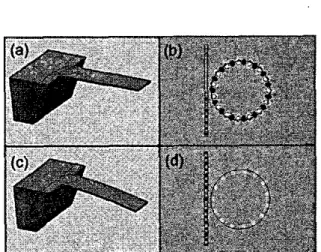
cantilever displacement with high accuracy. Fig.1 illustrates the the operational principle of the ring resonator displacement sensor.
11. RING RESONATOR AS DISPLACEMENT SENSOR
For the purpose of sensing displacement, we are mainly interested in modulation applications of ring resonators. It should be possible to obtain a large modulation in transmitted optical power by small variations of the refractive index. This kind of modulation is useful only if the resonance wavelength
Fig. I. A schematic illusualim of the operational principle for the imcgratcd
mi--dng resonator displacement sensor, (a and c) shows the cantileva for unbend and bend condition, (b and d) shows the field disuibution on the ring
resonator on the cantikvcr.
resonator is designed to have a high-Q factor, the modulation
is dramatic due to steep fall of the transmission dip. A ring resonator could have high Q-factors when designed to work at the critical conpliig regime.
As the operational principle of the ring resonator coupled waveguide sensor depends
on
the stress distribution along the cantilever,we have calculated the3D
stressdistribution
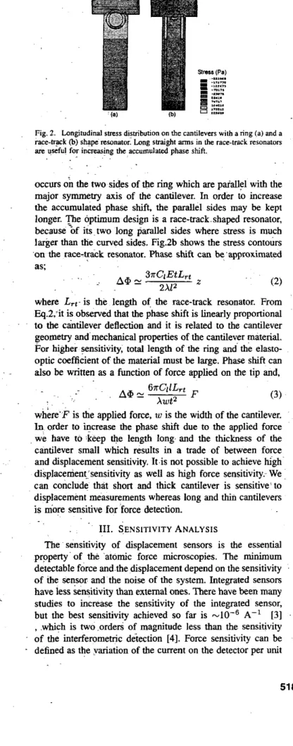
using Finite Element Method (FEM) simulations, for which; Young's Modulus of 0.83 x 10" N/mz, and Poisson's ratio of 0.31 were used. Static analysis was performed using ANSYS software. The mesh was increased in the region where ling resonator was placed. The analysis performed here uses the stress atthe surface. Maximum stress occurs at the suppotting point of the cantilever and decreases linearly along the cantilever. In Fig.2 we plot the stress distribution along the cantilever with an integrated ring resonator. Due to the photo-elastic effect, effective index changes due to the stress and through
the nn..ot:nn
..I* C'IUOLY"..,
(1)
shift remains in the bandwidth of the resonator. Such shifts path length of resonators, which is a function of resonator physical length and effective refractive index. Here, mess induced refractive index change is employed. When the ring
can only be achieved through a controllable change in optical n,ff = no
+
1
C,G
where, C, is the stress optic constant of waveguide and a, is
the local sfress. From Fig.Zb, it is clearly observed that stress
2.0110' 1.0110-
's
e
-1.0110' Z.0110' 1518.8 1549.2 1549.8Fig. 2. Lnngitudinal stress distribution on the cantilevm with a ring (a) and a race-@k (b) shape re~onmor. Long saaight arms in the race-tmck resonators
an useful for inneasing the accumulated phase shiti
. .
. .
.~
occurs on the
two
sides of the ring which are pafallel with the major symmetry anis of the cantilever. In order to increase the accumulated phase shift, the parallel sides may be kept longer. p i e optimum design is a race-track.shaped resonator, because%f i u ~ t w o long parallel sides where stress is much larger than the curved sides. Fig.2b shows the stress contours 'on the race-track resonator. Phase shift can be'aooroximated0.0
Wavelength (nm)
Fig. 3. Sensitivity vs wavelength for single bus ring resonator with critical
coupling achieved. ~.
force applied on the tip, with the same logic displacement sensitivity can be defined as the variation of the current on the detector per unit displacement of the cantilever. The detected power, It depends-on the transmission characteristics of the ring resonator coupled waveguide. We can write displacement and force sensitivities as
where Lrt is the length of the race-track resonator. From
Eq.2, it is observed that the phase shift is linearly proportional
to the cantilever deflection and it is related to the cantilever geometry and mechanical properties of the cantilever material. For higher sensitivity, total length of the ring and the elasto- optic coefficient of the material must be large. Phase shift can
also be written
as
a
function of force applied on the tip and,(3)
where
fl
is the correction factor. The highest sensitivities about2.5 10-4A-i are achieved under critical coupling conditions. The calculated sensitivities are promising, and it is possible to achieve sensitivities as high as the sensitivity of the in- terferometric detection. Sensitivity of the detector is depends mainly on the design of the resonator and the waveguide: The displacement sensitivity also depends on the wavelength of the light source. Fig.3 shows the sensitivity of the cantilever where'F is the applied force, w is the width of the cantilever. integrated with single bus ring resonator versus wavelength. In order to increase the Dbase shifl due to the aoolied force
we have to :keep *e length long and the thicgess of the IV. CONCLUSION
cantilever small which results in a trade of between force In this article, we propose a novel integrated ring resonator and displacement sensitivity. k i s not possible to achieve Ggh' displacement sensor for scanning force microscopies. We displacenient:sensitivity as well as high force sensitivity- We. design and analyze, the feasibility of the integra!ed opti.cal can conclude that short and thick cantilever is sensitive' to sensor. The concept based on elasto-optic effect is discussed. displacement measurements whereas long and thin cantilevers The design of the ring resonator was described and theoretical
is more sensitive
for
force detection. - investigation of the force and displacement sensitivity was111. S.ENSITIVITY ANALYSIS
The sensitivity of displacement sensors is the essential property of the 'atomic force microscopies. The minimum detectable force and.the displacement depend on the sensitivity
of the sensor and the noise of the system. Integrated sensors have less sensitivity than extemal ones. There have been many studies to increase the sensitivity of the integrated sensor, , which is two .orders of magnitude less than the sensitivity of the interferometric d&ection [4]. Force sensitivity can be defined as the variation of the current on the detector per unit
but the best sensitivity achieved so far is A-' 131
presented. We find that integrated optical sensor is attractive because of its high sensitivity about 10-4A:' and sirhplicity.
We introduce a. new application area for integrated~optics. This design is a good alternative for piezoresistive cantilevers especially in electromagnetically active environments. This method has high potential for improvement.
REFERENCES
[ I ] M. Tomnese et a1.1991 Proceeding of IEEE conferance on Trzndvcers 121 G. Meyer, N. M. Amer, Appl. Phys. Len. 53,(1988) 1045
[3] A. 1. Bmok, et al, 1. Micromech. Microeng. 13,(2003). 124 [4] D. Rug= et al. Appl. Phys. Leo 55. (1989). 2588
91. 448451