A new wireless asynchronous data communications module for
industrial applications
Yavuz Ege
a,⇑, Mehmet Gökhan Sßensoy
b, Osman Kalender
c, Sedat Nazlıbilek
d,e, Hakan Çıtak
fa
Balikesir University, Necatibey Faculty of Education, Department of Physics, 10100 Balikesir, Turkey
b
Middle East Technical University, Faculty of Arts and Sciences, Department of Physics, 06800 Ankara, Turkey
c
Bursa Orhangazi University, Faculty of Engineering, Department of Electrical-Electronics Engineering, 16350 Bursa, Turkey
d
Bilkent University, Nanotechnology Research Center (NANOTAM), 06800 Ankara, Turkey
e
Atilim University, Faculty of Engineering, Department of Mechatronics Engineering, 06800 Ankara, Turkey
fBalikesir University, Balikesir Vocational High School, 10100 Balikesir, Turkey
a r t i c l e
i n f o
Article history: Received 21 June 2012
Received in revised form 9 March 2013 Accepted 25 March 2013
Available online 18 April 2013 Keywords: ASK Analog data Microcontroller Asynchronous communications Serial port
a b s t r a c t
All the sensors such as temperature, humidity, and pressure used in industry provide ana-log outputs as inputs for their control units. Wireless transmission of the data has advan-tages on wired transmission such as USB port, parallel port and serial port and therefore has great importance for industrial applications. In this work, a new wireless asynchronous data communications module has been developed to send the earth magnetic field data around a ferromagnetic material detected by a KMZ51 AMR sensor. The transmitter mod-ule transmits the analog data obtained from a source to a computer environment where they are stored and then presented in a graphical form. In this design, an amplitude shift keying (ASK) transceiver working at the frequency of 433.92 MHz which is a frequency inside the so called Industrial Scientific Medical band (ISM band) used for wireless commu-nications. The analog data first fed into a 10-bit ADC controlled by a PIC microcontroller and then the digital data is sent to the transmitter. A preamble bit string is added in front of the data bits and another bit string for achieving synchronization and determination the start of the data is used. The data arriving at the receiver is taken by the microcontroller and sent to a LCD display as well as the serial port of a computer where it is written in a text file. A Visual Basic based graphics interface is designed to receive, store and present the data in the form of graphical shapes. In the paper, all the work has been explained in detail.
Crown Copyright Ó 2013 Published by Elsevier Ltd. All rights reserved.
1. Introduction
Wireless communication is a rapidly growing area for quick, easy and high quality data communications in industrial applications. In recent years, the most of the sen-sor based data collection and transmission processes are based on this technology. Wireless internet, data transfer through devices, automation systems, sensor networks,
etc. are some examples of it. Desiring transfer of more and more data cheaper and faster speeds up the develop-ments in wireless communications sector [1]. Wireless communication is the wide spread application domain in electronics. It needs a carrier wave which makes it possible to transfer information in long distances in air or space. A wide range of the spectrum can be used for choosing the carrier. The most preferable choices may be to use infrared, laser and radio waves[2]. RF waves or signals cover the fre-quency range between 3 kHz and 3000 GHz. In this range, the spectrum has been divided as VLF, LF, MF, HF, VHF, UHF, etc. In recent years, the studies are concentrated on
0263-2241/$ - see front matter Crown Copyright Ó 2013 Published by Elsevier Ltd. All rights reserved.
http://dx.doi.org/10.1016/j.measurement.2013.03.028
⇑ Corresponding author. Tel.: +90 266 241 27 62x143; fax: +90 266 241 12 12.
E-mail address:[email protected](Y. Ege).
Measurement
the application frequency, transmission rate, communica-tions direction (dual or single) and reduction of energy consumption. Different types of receiver and transmitter modules have been designed taken into account the above mentioned variables. Among them ASK transceiver sys-tem-on-package (SoP) compact module working at 60 GHz[3,4], 8 Gbps CMOS ASK modulator[5], low-power ASK receiver[6–10], Single-Band RF Front-End (FEM) Mod-ule[11], compact radio-frequency (RF)/free space optical (FSO) dual mode wireless communication system[12,13]. Furthermore, low power, variable gain RF transceivers at 900 MHz have also been studied[14–16].
In communications applications only some parts of the bands can be used. Among them, the ISM (Industrial Scien-tific Medical band) band can be used without any cerScien-tifica- certifica-tion or license in case obeying the power limitacertifica-tion rules. In Turkey, the frequencies commonly used in ISM band are 315 MHz, 418 MHz, 433.92 MHz, 868 MHz, 915 MHz, and 2.4 GHz. Today, modules working at these frequencies are effectively used in most technological applications such as measuring internal and external torques in real time within modern ship control systems[17], remote con-trol systems of cars[16]and wireless sensor networks[18]. In this work, a new wireless real time asynchronous data communications module has been developed for sending the earth magnetic field data around a
ferromag-netic material detected by a KMZ51 AMR sensor. It can also easily be used for sensors such as temperature, humidity and pressure producing analog voltage for control units and used mainly in industry. This module can send the sen-sor voltage at 433.92 MHz with a resolution of 10-bit un-der the control of user at irregular time intervals. The data received by the receiver module can be stored in a PC. The data is graphically presented in real time by means of the software developed by Visual Basic. The details are given in the following sections of the paper.
2. Data communication system
The data communication system developed in this work is composed of two main units as the transmitter unit and the receiver unit. Now, we can analyze these two units in detail in the following sub sections.
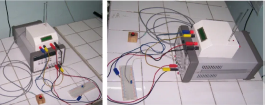
Fig. 1. Transmitter unit.
2.1. Transmitter unit
In transmitter unit, the analog signal is converted to a digital data and it is transmitted by a RF module having an ASK modulator with 433.92 MHz oscillator. The trans-mitter unit is shown inFig. 1.
The transmitter module (ATX) within the transmitter unit does not have a voltage regulator. It is fed from an external power. ATX module can be operated by a battery. A DIN pin is available at the ATX-34 module for digital data input. The DIN pin is the input from where the data to be
sent by the RF system can be applied by the user. It is needed to convert the analog data to a 10-bit digital data before transmission. To do this, we use the analog-to-dig-ital conversion capability of PIC16F877 microcontroller. The standard data protocol is given inFig. 2.
Start information is needed at the beginning of a mes-sage even if it is the simplest communications system. Start part is a bit string consisting of consecutive 1’s and 0’s (010101. . .). Some characters could be chosen as the start part. The durations of 1’s and 0’s must be equal. In short, the start part provides synchronization for the
Fig. 3. Photograph of the transmitter unit.
hardware. Synchronization part of the digital message helps the synchronization of the software. In order to achieve bit synchronization and correctly determine the start of the message, availability of these two parts is important. In this work, characters such as için ‘‘M’’, ‘‘G’’ and ‘‘S’’ are used for start and synchronization parts. Recei-ver circuit waits until receiving these characters and then extracts the data coming after these parts and sends it to the computer by the microcontroller.
As seen inFig. 1, first of all the analog data detected is converted to a 10-bit digital form by means of the PIC16F877 microcontroller. And then the microcontroller sends this data to C and D ports. The main purpose here is to write each bit of 10-bit data to the ports of the
micro-controller one by one. By doing so, we can obtain a serial data. In this way, all the bits of the digital data can be sent from A1 port of the microcontroller to transmitter module by using ‘‘Serout2’’ command. ATX-34 transmitter module can send the 10-bit digital data to ARX-34 receiver module by using the standard data protocol shown inFig. 2.
The analog data can be sent under the control of the user. The data transmission is active as soon as the user pushes the button (Fig. 1). Otherwise, the analog data is converted to a 10-bit digital data and is only displayed at the LCD display.Fig. 3depicts a photograph of the trans-mitter unit developed in this work. The control program of PIC16F877A microcontroller written in Pic Basic Pro is given in theAppendix A.
Fig. 5. Block diagram of transmitting and receiving of analog signal.
Fig. 6. A photograph of the receiver unit developed in this work.
2.2. Receiver unit
In the receiver unit, the 10-bit digital data is received by an ASK type receiver RF module having a 433.92 MHz oscillator and it is sent to the serial port of a PC by means
The data coming to the ARX-34 receiver module is also written on the LCD display simultaneously. The 10-bit data stored in PIC16F84A is not sent immediately to the serial port. Instead, a logical-1 signal is sent from the A2 port of the PIC to the parallel port of the PC for synchronization purpose. This helps to start the data storage program which is used to receive the serial data from the serial port. The program sends a character ‘‘A’’ to the PIC16F84A through the serial port and receives the 10-bit data. The block diagram for sending and receiving an analog signal to a computer through a wireless medium is given inFig. 5. A photograph of the receiver unit developed in this work is shown inFig. 6. The control program of PIC16F84A with Pic Basic code is given in theAppendix B.
3. Software
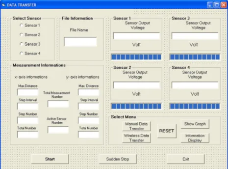
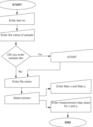
In this work, the analog data is the signal obtained by a KMZ51 AMR sensor. The sensor can move in two dimen-sions in the x–y plane where a magnetic material is avail-able. It senses the earth magnetic field around the material. The program developed can have the capability to take the data coming from four different sensors. The user interface of the software that we developed here is seen inFig. 7. It is Visual Basic based software that it en-ables the user to control data to be entered to the com-puter through the receiver unit. When the ‘‘start’’ button is pressed, it is requested from user that a test number, name of the test material, dimensions of material and name of the file storing the data have to be entered. If there is no need to enter the dimensions of the material, it can be skipped to last step and the name of the file is requested to enter. Next, the sensor number from which the data is
Fig. 8. Flow diagram of the program.
collected, the dimensions of area to be scanned and step size of data collection are entered. In this way, the program will be ready to transfer sensor data to computer.
After entering the necessary information, the ‘‘Get Data’’ command is waited. For this, a button is used at the trans-mitter unit. In each Get Data command, the program reads the sensor data, write it to program interface and store it to the opened file. If the user wants to read the magnitude of the sensor voltage without storing it, he/she has to use ‘‘Get Data’’ button. The variations of the sensor voltage detected can be observed by pressing the ‘‘Show Graphics’’ button. The data collected here can simultaneously be plotted in two dimensions. A data collection process can be broken at any time immediately and then it can be started again
from the same point by using ‘‘Immediate Stop’’ button. A user can reach the information of geometric properties of test material, sensor position and instantaneous data visu-ally by pressing the ‘‘Information Screen’’ button. The ‘‘Re-set’’ button can reset the sensor to its starting position. The program can be closed by pressing the ‘‘Exit’’ button. A flow diagram related to the operation of the program is given inFig. 8.
When the information screen command button is pressed, the screen shown inFig. 9appears in the com-puter display. This screen can enable the user to see sensor movement, measurement point, sensor position and general properties of the test material simultaneously.
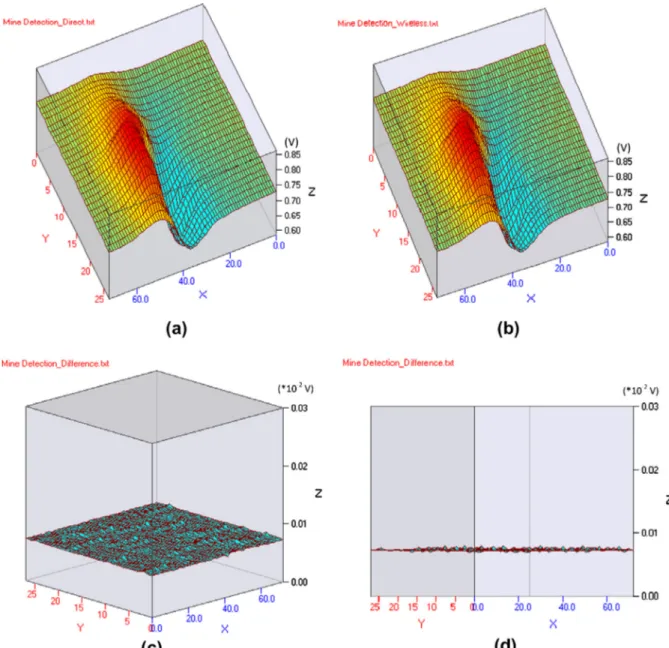
Fig. 10. With respect to the scanning area: (a) changes of signal amplitudes obtained directly, (b) changes of signal amplitudes obtained by wireless transfer, (c) change of the differences between of the signal amplitudes obtained directly and by wireless transfer (top view) and (d) change of the differences between of the signal amplitudes obtained directly and by wireless transfer (cross-sectional view).
In the scope of our work, the wireless asynchronous communications module is also tested for proving the data transfer operation. For this purpose, first of all the analog data coming from the KMZ51 AMR sensor after x–y area scanning for mine detection is recorded to the transmitter unit in directly and wireless transfer, Then the signal amplitudes with respect to the scanning area are plotted
(Fig 10a and b). At last, the differences of data obtained
by both directly and wireless method is plotted (Fig 10c and d). Hence, it is determined that wireless could be sat-isfied with the error ration of 0.00977%.
4. Conclusion
In this work, a new real time asynchronous data com-munications module has been developed. By using this module, an analog data can be transmitted at a frequency of 433.92 MHz to a distance of 100 m without any prob-lem. Transferred data can be converted to a graphical form simultaneously. In order to introduce the advantages and disadvantages of the real-time asynchronous data commu-nications module developed in this work, the technical information related to some of the studies in the literature that are similar to our work are given inTable 1.
As seen fromTable 1, the other modules in the litera-ture have been designed for data transfer at low signal power, high frequency abd 10-bit resolution (including parity bit). They have not been designed for instantaneous transfer of experimental measurement results. However, their range is longer than ours because of the frequency used. In our system, the data transfer can be achieved with a high accuracy without using a parity bit but with a high signal power. It may be considered that our system has a disadvantage of shorter range due to the low frequency that we used.
This type of product can easily be adapted to tempera-ture, humidity or pressure (hydraulic or pneumatic) con-trolled systems. Furthermore, the module is appropriate for all kinds of sensor outputs. The data storage program can access four different sensor data simultaneously. It can easily be extended for more than four sensor units if needed. The following properties such as high resolution and being under user control can be considered as advan-tageous for most applications. As we mentioned, it has a 10-bit resolution and it can be controlled to operate by pressing a button. Our next study will include a cell phone unit to send a SMS message when the data exceeds the de-sired levels.
Appendix A
‘Pic basic codes of transmitting’ DEFINE LCD_EREG PORTB ’LCD ENABLE pin connects to PORTB
’⁄⁄⁄⁄⁄Define input and output⁄⁄⁄⁄⁄ DEFINE LCD_EBIT 3 ’LCD ENABLE pin connects to PORTB.3
TRISA=%00000001 ’PORTA.0 Analog input DEFINE LCD_RSREG PORTB ’LCD RS pin connects to PORTB
TRISB=0 ’2⁄16 LCD output ports DEFINE LCD_RSBIT 2 ’LCD RS pin connects to PORTB.2
TRISC=0 ’RW pin is connected to ground.
TRISD=0
’⁄⁄⁄⁄⁄LCD Define⁄⁄⁄⁄⁄ ’⁄⁄⁄⁄⁄ADC Define⁄⁄⁄⁄⁄
DEFINE LCD_DREG PORTB ’LCD DATA pins connect to PORTB
INCLUDE ‘‘MODEDEFS.BAS’’
DEFINE LCD_DBIT 4 ’LCD DATA pins connect to PORTB.4 DEFINE ADC_BITS 10 ’ADC 10 BIT DEFINE ADC_CLOCK 3
DEFINE ADC_SAMPLEUS 50 ’Sampling Time 50 Microsecond
IF PORTC.5=1 THEN CIKIS VAR WORD ’ADC_DEGER is defined 16 BIT type of
WORD
X5=32
BILGI VAR WORD ELSE
(continued on next page)
Frequency (GHz) Resolution (Bit) Signal output power (dB m) Purpose Range (km) Reference
60 10 (with parity bit) 12.8 File transfer 1 [4]
8 10 (with parity bit) 26.6 File transfer 0.7 [5]
2 10 (with parity bit) 1.2 File transfer 0.4 [11]
2.5 10 (with parity bit) 15–20 File transfer 0.5 [10]
0.9 10 (with parity bit) 2 File transfer 0.3 [14]
Appendix A (continued)
VERI1 VAR WORD X5=0
VERI2 VAR WORD ENDIF
VERI3 VAR WORD
VERI4 VAR WORD IF PORTC.6=1 THEN
VERI5 VAR WORD X6=64
X0 VAR BYTE ELSE
X1 VAR BYTE X6=0
X2 VAR BYTE ENDIF
X3 VAR BYTE
X4 VAR BYTE IF PORTC.7=1 THEN
X5 VAR BYTE X7=128
X6 VAR BYTE ELSE
X7 VAR BYTE X7=0
X8 VAR WORD ENDIF
X9 VAR WORD
SYMBOL VERIOUT=PORTA.1 IF PORTD.0=1 THEN
SYMBOL VERIOUT2=PORTA.2 X8=255
ADCON1=%10000010 ’Port define for 10 Bit ADC ELSE
PAUSE 500 X8=0
LCDOUT $fe,1 ENDIF
LCDOUT $fe,$82,’’SENSOR CIKISI’’ IF PORTD.1=1 THEN
BASLA: X9=512
PORTD.7=0 ELSE
ADCIN 0,CIKIS ’Read value of ADC by using port AN0 X9=0
BILGI=CIKIS⁄48/10 ENDIF
VERI1=0 VERI2=0
’10-bit data is matched port C’ VERI5=0
VERI3=0 PORTC.0=CIKIS.BIT0 VERI4=0 PORTC.1=CIKIS.BIT1 PORTC.2=CIKIS.BIT2 VERI1=X0+X1+X2+X3+X4+X5+X6+X7 PORTC.3=CIKIS.BIT3 VERI2=X8+X9 PORTC.4=CIKIS.BIT4
PORTC.5=CIKIS.BIT5 IF VERI2=512 THEN
PORTC.6=CIKIS.BIT6 VERI2=0
PORTC.7=CIKIS.BIT7 VERI2=2
PORTD.0=CIKIS.BIT8 VERI3=255
PORTD.1=CIKIS.BIT9 VERI4=255
‘Collecting each data bit’ ENDIF
IF PORTC.0=1 THEN IF VERI2=767 THEN
X0=1 VERI2=0
ELSE PAUSE 10
X0=0 VERI2=255
ENDIF VERI3=255
VERI4=255
IF PORTC.1=1 THEN VERI5=2
X1=2 ENDIF
ELSE
X1=0 IF PORTD.7=0 THEN GOTO BASLA
ENDIF IF PORTD.7=1 THEN
GOSUB LCD
IF PORTC.2=1 THEN GOSUB VER
X2=4 ENDIF
ELSE
X2=0 PAUSE 10
ENDIF GOTO BASLA
IF PORTC.3=1 THEN ‘Data transmitting from the transmitter’
ELSE VER:
X3=0 SEROUT2 VERIOUT,813,[REP$AA/5,REP$00/5,REP$FF/5]
ENDIF SEROUT2 VERIOUT,813,[’’M’’,’’G’’,’’S’’,VERI1]
SEROUT2 VERIOUT,813,[’’M’’,’’G’’,’’S’’,VERI1]
IF PORTC.4=1 THEN SEROUT2 VERIOUT,813,[’’G’’,’’T’’,’’S’’,VERI2]
X4=16 SEROUT2 VERIOUT,813,[’’G’’,’’T’’,’’S’’,VERI2]
ELSE SEROUT2 VERIOUT,813,[’’A’’,’’R’’,’’S’’,VERI3]
X4=0 SEROUT2 VERIOUT,813,[’’A’’,’’R’’,’’S’’,VERI3]
ENDIF SEROUT2 VERIOUT,813,[’’A’’,’’N’’,’’S’’,VERI4]
SEROUT2 VERIOUT,813,[’’A’’,’’N’’,’’S’’,VERI4] RETURN SEROUT2 VERIOUT,813,[’’A’’,’’A’’,’’A’’,VERI5]
SEROUT2 VERIOUT,813,[’’A’’,’’A’’,’’A’’,VERI5] END SEROUT VERIOUT2,N2400,[CIKIS]
RETURN LCD:
LCDOUT $FE,$C1 ’Clear LCD data LCDOUT ‘‘CIKIS ‘‘,DEC5 BILGI,’’mV’’ PAUSE 200
Appendix B
‘Pic basic codes of receiving’ BILGI4=0
INCLUDE ‘‘MODEDEFS.BAS’’ BILGI5=0
Define LCD_BITS 4 SERIN2 VERIIN,813,[WAIT (‘‘MGS’’),BILGI1]
Define LCD_DREG PORTB SERIN2 VERIIN,813,[WAIT (‘‘GTS’’),BILGI2]
DEFINE LCD_DBIT 4 SERIN2 VERIIN,813,[WAIT (‘‘ARS’’),BILGI3]
DEFINE LCD_RSREG PORTB SERIN2 VERIIN,813,[WAIT (‘‘ANS’’),BILGI4]
DEFINE LCD_RSBIT 0 SERIN2 VERIIN,813,[WAIT (‘‘AAA’’),BILGI5]
DEFINE LCD_EREG PORTB BILGI=(BILGI1+BILGI2+BILGI3+BILGI4+BILGI5)⁄48/10
DEFINE LCD_EBIT 1
PORTA=0 PORTA.3=1
TRISA=%11111111 SERIN VERIIN2,N1200,KONTROL
TRISB=0 IF KONTROL=65 THEN
BILGI VAR WORD SEROUT VEROUT,N1200,[BILGI1]
BILGI1 var WORD PAUSE 100
BILGI2 VAR WORD SEROUT VEROUT,N1200,[BILGI2]
BILGI3 VAR WORD PAUSE 100
BILGI4 VAR WORD SEROUT VEROUT,N1200,[BILGI3]
BILGI5 VAR WORD PAUSE 100
KONTROL VAR BYTE SEROUT VEROUT,N1200,[BILGI4]
SYMBOL VERIIN=PORTA.0 PAUSE 100
SYMBOL VEROUT=PORTB.3 SEROUT VEROUT,N1200,[BILGI5]
SYMBOL VERIIN2=PORTA.2 PAUSE 100
‘received data are collecting and writing form of 10-bits’ LCDOUT $FE,1
LCDOUT ‘‘ SENSOR VOLTAJI’’
MAIN: LCDOUT $FE,$C0,’’ ‘‘,DEC5 BILGI,’’mV’’
BILGI=0 ’PAUSE 200
BILGI1=0 GOTO MAIN
BILGI2=0 END
References
[1] John R. Vacca, Wireless Data Demystified, The McGraw-Hill Companies, USA, 2003.http://dx.doi.org/10.1036/0071429190. [2] Cheng Tao, Peltonen Teemu, Tjukanoff Esa, et al., RF transceiver
circuit technology based wireless interconnects for inter- and intra-chip communication system, in: EPTC: 2008 10th Electronics Packaging Technology Conference, Book Series: Electronics Packaging Technology Conference Proceedings, vols. 1–3, 2008, pp. 1409–1414.
[3] Young Chul Lee, Tae-Wan Kim, Azzemi Ariffin, Implementation of ASK transceiver system-on-package (SoP) module for 60 GHz wireless communication applications, in: 8th WSEAS International Conference on Telecommunications and Informatics Location, Istanbul, Turkey, May 30–June 01, 2009.
[4] Ho-Hsin Yeh, Nobuki Hiramatsu, Kathleen L. Melde, Wireless RF data communications using 60 GHz antennas in multi-core systems, in: 2011 IEEE 20th Conference on Electrical Performance of Electronic Packaging and Systems (EPEPS), Book Series: IEEE Conference on Electrical Performance of Electronic Packaging and Systems – EPEPS, 2011, pp. 31–34.
[5] Ahmet Oncu, Kyoya Takano, Minoru Fujishima, 8 Gbps CMOS ASK modulator for 60 GHz wireless communication, in: 4th IEEE Asian Solid-State Circuits Conference Location, Fukuoka, Japan, November 03–05, 2008.
[6] T. Yazaki, H. Yamamoto, A. Hyogo, et al., Low-power ASK receiver circuit for wireless communication system, in: Asia-Pacific Conference on Circuits and Systems Location, Bali, Indonesia, October 28–31, 2002.
[7] Inke Jones, Lucas Ricciardi, Leonard Hall, et al., Wireless RF communication in biomedical applications, Smart Materials and Structures 17(1) (2008).http://dx.doi.org/10.1088/0964-1726/17/1/ 015050(article number 015050).
[8] Shailesh B. Nerurkar, Khalid H. Abed, Low power digital decimation filter for RF wireless communications, Journal of Circuits Systems and Computers 17 (2) (2008) 239–251,http://dx.doi.org/10.1142/ S0218126608004241.
[9] D.M.W. Leenaerts, Low power RF IC design for wireless communication, in: ISLPED’03: Proceedings of the 2003
International Symposium on Low Power Electronics and Design, 2003, pp. 428–433.
[10] C.E. Weitzel, RF power amplifiers for wireless communications, in: GaAs IC Symposium – 24th Annual Technical Digest 2002, Book Series: Technical Digest – IEEE Gallium Arsenide Integrated Circuit Symposium, 2002, pp. 127–130.
[11]Dong Ho Kim, Dongsu Kim, Jun Chul Kim, et al., A novel single-band RF front-end module for wireless communication systems, Microwave and Optical Technology Letters 53 (6) (2011) 1349– 1352.
[12] Jun Liao, Juan Zeng, Shengling Deng, et al., Packaging of dual-mode wireless communication module using RF/optoelectronic devices with shared functional components, IEEE Transactions on Advanced Packaging 33 (2) (2010) 323–332, http://dx.doi.org/10.1109/ TADVP.2009.2038359.
[13] Anatoliy Boryssenko, Jun Liao, Juan Zeng, et al., Studies on RF-optical dual mode wireless communication modules, in: IEEE/MTT-S International Microwave Symposium Location, Boston, June 07–12, 2009.
[14] Trung-Kien Nguyen, A low-power, wide-range variable gain CMOS RF transmitter for 900 MHz wireless communications, Analog Integrated Circuits and Signal Processing 63 (2) (2010) 177–183,
http://dx.doi.org/10.1007/s10470-009-9406-7.
[15] Seung-Sik Lee, Sangjae Lee, Sangsung Choi, et al., A WiX RF transceiver for Gbps wireless communication, in: IEEE International Conference on Consumer Electronics (ICCE 2011), 2011, pp. 427–428.
[16]Andreas Riemann, RF simplifies in-car wireless communications, Electronics World 112 (1848) (2006) 24–26.
[17] Yiqun Xu, Guannan Yang, Dujiang Chen, The macro test of torque based on RF wireless communication, in: 2009 3RD International Conference on Anti-Counterfeiting, Security, and Identification in Communication, 2009, pp. 4–6. http://dx.doi.org/10.1109/ICEMI. 2009.5274697.
[18]Farukh Nadeem, S. Chessa, E. Leitgeb, et al., The effects of weather on the life time of wireless sensor networks using FSO/RF communication, Radioengineering 19 (2) (2010) 262–270.