MOVING OBJECT DETECTION AND
TRACKING IN WAVELET COMPRESSED
VIDEO
A THESIS
SUBMITTED TO THE DEPARTMENT OF ELECTRICAL AND
ELECTRONICS ENGINEERING
AND THE INSTITUTE OF ENGINEERING AND SCIENCE
OF BILKENT UNIVERSITY
IN PARTIAL FULFILLMENT OF THE REQUIREMENTS
FOR THE DEGREE OF
MASTER OF SCIENCE
By
Behçet Uğur Töreyin
August 2003
I certify that I have read this thesis and that in my opinion it is fully adequate, in scope and in quality, as a thesis for the degree of Master of Science.
Prof. Dr. A. Enis Cetin (supervisor)
I certify that I have read this thesis and that in my opinion it is fully adequate, in scope and in quality, as a thesis for the degree of Master of Science.
Prof. Dr. Levent Onural
I certify that I have read this thesis and that in my opinion it is fully adequate, in scope and in quality, as a thesis for the degree of Master of Science.
Prof. Dr. Billur Barshan
Approved for the Institute of Engineering and Science
Prof. Dr. Mehmet Baray Director of the Institute
ABSTRACT
MOVING OBJECT DETECTION AND TRACKING
IN WAVELET COMPRESSED VIDEO
Behçet Uğur Töreyin
M.S. in Electrical and Electronics Engineering
Supervisor: Prof. Dr. A. Enis Çetin
August 2003
In many surveillance systems the video is stored in wavelet compressed form. An algorithm for moving object and region detection in video that is compressed using a wavelet transform (WT) is developed. The algorithm estimates the WT of the background scene from the WTs of the past image frames of the video. The WT of the current image is compared with the WT of the background and the moving objects are determined from the difference. The algorithm does not perform inverse WT to obtain the actual pixels of the current image nor the estimated background. This leads to a computationally efficient method and a system compared to the existing motion estimation methods. In a second aspect, size and locations of moving objects and regions in video is estimated from the wavelet coefficients of the current image, which differ from the estimated background wavelet coefficients. This is possible because wavelet coefficients of an image carry both frequency and space information. In this way, we are able to track the detected objects in video. Another feature of the algorithm is that it can determine slowing objects in video. This is important in many practical applications including highway monitoring, queue control, etc.
Keywords: wavelet transform, intra-frame compression, background subtraction, video object tracking, non-linear voting, video-based surveillance systems.
ÖZET
DALGACIK DÖNÜŞÜMÜYLE SIKIŞTIRILMIŞ
VİDEODA HAREKETLİ NESNE TESPİTİ VE
TAKİBİ
Behçet Uğur Töreyin
Elektrik ve Elektronik Mühendisliği Bölümü Yüksek Lisans
Tez Yöneticisi: Prof. Dr. A. Enis Çetin
Ağustos 2003
Görüntü tabanlı pek çok güvenlik sisteminde sıkıştırma yöntemi olarak dalgacık dönüşümü kullanılmaktadır. Bu çalışmada, dalgacık dönüşümüyle sıkıştırılmış videolarda, hareketli nesne tespiti ve takibiyle ilgili bir yöntem geliştirilmiştir. Yöntem, her resim için arka plana ait dalgacık dönüşümü katsayılarının kestirilmesi esasına dayanmaktadır. Mevcut andaki resme ait dalgacık dönüşümü katsayıları, arkaplana ait katsayılarla karşılaştırılarak, hareketli nesneler tespit edilmektedir. Yöntem dalgacık dönüşümünün tersini almadan hareketli nesneleri bulabildiği için diğer yöntemlere göre çok daha az işlem gerektirir. Diğer taraftan, hareketli nesnelerin büyüklükleri ve konumları da tespit edilebilmektedir. Bu, dalgacık dönüşümünün hem konum hem de sıklık bilgisi içermesi sayesinde mümkün olmaktadır. Nesne takibi böylelikle gerçekleştirilmiştir. Yöntemin bir başka özelliği de yavaşlayan ve duran nesneleri de tespit edebiliyor olmasıdır. Bu da, otoyol görüntülenmesi, sıra denetimi, vb. pekçok uygulama için önemli bir özelliktir.
Anahtar kelimeler: dalgacık dönüşümü, resim içi sıkıştırma, arkaplan kestirimi, video nesnesi, takip etme, doğrusal olamayan oylama, görüntü tabanlı güvenlik sistemleri.
Acknowledgement
I would like to express my gratitude to Prof. Dr. A. Enis Çetin for his supervision, suggestions and encouragement throughout the development of this thesis.
I am also indebted to Prof. Dr. Levent Onural and Prof. Dr. Billur Barshan accepting to read and review this thesis and for their suggestions.
It is my honor to express my appreciation to Aykut Özsoy, Erdem Dengel and Yiğithan Dedeoğlu for their valuable contributions, corrections and discussions.
It is a great pleasure to express my special thanks to my family, Yılmaz, Meral, Nur and Hakan Töreyin who brought me to this stage with their endless patience and dedication. Finally, I would like to thank to my wife, Gülnihal, for her unconditional love and interest she has shown during all the stages of this thesis.
Contents
1 Introduction 1
1.1 Motivation………..5
1.2 Organization of the Thesis……….7
2 Related Work 8
3 Moving and Left Object Detector 11
3.1 Hybrid Algorithm for Moving Object Detection………12
3.2 Detection in Wavelet Domain……….18
3.3 Detection Results and Discussion………...30
4 Object Tracker 35
4.1 Features for Tracking………..41
4.2 Voting Based Scheme……….42
4.2.1 Object Voting………43
4.3 Linear Cost Function Scheme……….46
4.3.1 Linear Cost Function……….46
4.3.2 Matching and Conflict Resolution………47
4.4 Occlusion Handling……….51
4.5 Stopped and Slow Object Detection………53
4.6 Tracking Results and Discussion……….54
List of Figures
1.1 Architectural scheme of 3GSS………..5 3.1 Block diagram illustrating the proposed system for characterizing
the motion of moving regions in an image sequence forming a video by comparing the current image with the background
image estimated from the current and past images of the video…….17 3.2
3.3
3.4
3.5
Diagrammatic illustration of the transformation of an image into a one-level wavelet transformed image……….…………..19
Wavelet transform up to fifth level is performed to the original image on the left. The wavelet transform tree corresponding to the original image, depicting third, fourth and
fifth levels is on the right……….21 A block diagram illustrating the proposed system for characterizing
the motion of moving regions in wavelet compressed video by comparing the wavelet transform of the current image with the wavelet transform of background image estimated from the current and past images of the video………...28 Moving pixels detected by the system are shown………...31
3.6 3.7
Immediate neighborhood of pixel located at (i,j)………31
Minimum bounding box encapsulating the pixels classified as moving………32
4.1 Framework of the tracker. Current, In, and previous, In-1, frames are fed into the detection part producing the current, On, and previous, On-1, objects. At the output of the tracker, object trajectories are determined………39
4.2 A directed network representation of the assignment problem……...47
4.3 Modified, rather simplified successive shortest path algorithm for our fix topology network………...50
4.4 Object in the nth frame is formed by the unification of the (n-1)st frame objects in its vicinity……….52
4.5 Occlusion examples……….57
4.6 A parking lot environment with lots of moving objects………..58
4.7 A car departing from the parking lot………58
List of Tables
3.1 Lowpass and Highpass filter coefficients………26 3.2 Time performance comparison between 3 main sensitivity levels….33 3.3 Time performance comparison between 3 main sensitivity levels….34 4.1 Comparison for several sequences at 5 fps……….55 4.2 Time performance comparisons………..56
Chapter 1
Introduction
A surveillance system can be defined as a technological tool that helps humans by providing extended perception and reasoning capability about situations of interest that occur in the monitored environments [1,2]. Human perception and reasoning are constrained by the capabilities and the limits of the human senses and mind which collaboratively collect, process and store limited amount of data. Human beings can sense and process data coming from only a spatially limited area at a given time. Surveillance systems extend this limited perception capability of humans.
Surveillance systems have various application areas:
- safety in transport applications, such as monitoring of railway stations, underground stations, airports, motorways, urban and city roads, maritime environments
- safety or quality control in industrial applications, such as monitoring of nuclear plants or industrial processing cycles
CHAPTER 1. INTRODUCTION 2
- security applications, such as monitoring of indoor or outdoor environments like banks, supermarkets, car parking areas, waiting rooms, buildings, etc., remote monitoring of a patient, remote surveillance of human activity.
Among various sensing modalities in a surveillance system, like chemical sensing or audio, visual information processing and understanding modality have the most important and crucial part. This fact is due to several aspects of visual data:
- Temporally organized visual information is the major source of human information about the surrounding environment.
- As the number of cameras increase, event monitoring by personnel is rather boring, tedious, and erroneous at times. The automatic preprocessing of the video information by a surveillance system can act as a pre-filter to human validation of the events. Therefore, it is mandatory to manage the complexity of monitoring a large site somehow. Besides, presenting the events occurring in a large monitored area to the personnel in a user-friendly manner is the most suitable approach.
- The cost of a video sensor is much lower compared to other sensing mechanisms when the area of coverage and event analysis functionalities provided by using video as the sensing modality for monitoring are taken into consideration.
- A large body of knowledge exists in the areas of robust and fast digital communication, video processing, and pattern recognition. These facilitate the development of effective and robust real-time systems.
CHAPTER 1. INTRODUCTION 3
Video-based surveillance systems can be grouped in three successive generations, historically. The three generations follow the evolution of communications, processing, and storage technologies. 1960s can be considered to be the starting date of video surveillance systems as close circuit television systems (CCTV) were operative in the market and providing data at acceptable quality at those times.
First generation video surveillance systems (1GSS) (1960-1980) basically extend the human perception capabilities in spatial sense. More eyes are used to monitor a large area. The analog visual signals from distant locations are collected and displayed in a single control room. 1GSSs are based on analog signal and image transmission and processing. From the processing point of view, one major drawback of these systems is that they are mostly dependent on the limited attention spans of the human operators who inspect the monitors in the control room.
Then comes the next generation (2GSS) in video surveillance which spanned mainly the last two decades. It corresponds to the maturity stage of the 1GSSs; they benefited from the early advances in digital technology (e.g., digital compression, bandwidth reduction, and robust transmission) and processing methods that provide assistance to the human operator by prescreening of important visual events. Most of the research efforts during the period of 2GSSs have been spent to the development of automated real-time event detection techniques for video surveillance. Consequently, advanced perception capability in 2GSSs allowed for a significant increase in the amount of simultaneously monitored data and, in addition, provided an alarm data directly relevant to the cognitive monitoring tasks. However, those systems still included digital methods to solve local and isolated problems. They didn’t make use of digital technology in the whole system.
CHAPTER 1. INTRODUCTION 4
The main idea behind the third generation surveillance systems (3GSS) is to provide full digital solutions to the design of the systems, starting at the sensor level, all the way up to the operators.
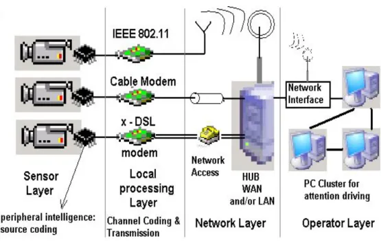
In Figure 1.1, an architectural scheme of 3GSS is presented. Video cameras constitute the sensor layer, while the peripheral intelligence and the transmission devices form the local processing layer. These two can be physically organized together to form an intelligent camera. The local processing layer uses digital compression methods, including wavelet coding, to save bandwidth resources. The principal component in the network layer is the intelligent hub which fuses the data coming from lower layers in an application oriented manner. At the operator layer, an interface is presented to the operator. This interface draws the attention of the operator to a subset of interesting events. All communications throughout the entire system is digital.
To implement a full digital surveillance system, improvements in automatic recognition functionalities and digital multi-user communications strategies are needed. Technology meeting the requirements for the recognition algorithms includes computational speed, memory usage, remote data access, multi-user communications between distributed processors, etc. In this study, we address the problems of computational speed and memory usage for the recognition methods, and propose a system which makes use of the compressed data to extract the needed cognitive information from the visual content.
CHAPTER 1. INTRODUCTION 5
Figure 1.1: Architectural scheme of 3GSS.
1.1. MOTIVATION
Compression of the digital data coming from the sensors has been an indispensable part of surveillance systems since 2GSSs. Hence, several transforms have been used for coding of this huge amount of data. In many video based surveillance systems, the video is compressed intra-frame only, without performing motion compensated prediction due to legal reasons. Courts do not accept predicted image frames as legal evidence in many European countries. As a result, a typical surveillance video is composed of a series of individually compressed image frames. In addition, many practical systems have a built-in VLSI hardware image compressor directly storing the video data coming from several cameras into a hard disc.
CHAPTER 1. INTRODUCTION 6
In this study, it is assumed that the video data is stored using a wavelet compressor in the wavelet domain. In most of the video based surveillance systems used today, the visual data is stored in wavelet compressed form for its superior features compared to the discrete cosine transform. In many multi-channel real-time systems, it is not possible to use uncompressed video due to available processor limitations. Thus, we developed an algorithm for moving object and region detection in compressed video using a wavelet transform (WT). A tracker is also added to the system which successfully keeps track of the objects, handles occlusions with two occluding bodies, again by making use of the wavelet coefficients of the video data.
The algorithm estimates a wavelet transform of the background scene from the wavelet transforms of the past image frames of the video. The wavelet transform of the current image is compared with the WT of the background and the moving objects are determined from the difference. The algorithm does not perform inverse wavelet transform to obtain the actual pixels of the current image nor the estimated background. This leads to a computationally efficient method and a system compared to the existing motion estimation methods. In a second aspect, size and locations of moving objects and regions in video is estimated from the wavelet coefficients of the current image, which differ from the estimated background wavelet coefficients. This is possible because wavelet coefficients of an image carry both frequency and space information. Another feature of the algorithm is that it can determine slowing objects in video. This is important in many practical applications including highway monitoring, waiting room monitoring, etc.
CHAPTER 1. INTRODUCTION 7
1.2. ORGANIZATION OF THE THESIS
The thesis is organized as follows: Chapter 2 presents a survey of the prior studies on moving object detection methods and systems. In Chapter 3, the proposed method for moving and left object detection is explained in detail. Chapter 4 includes the explanation of the tracker used in the system. Finally, Chapter 5 concludes the thesis.
Chapter 2
Related Work
In [17], Plasberg describes an apparatus and a method for the detection of an object moving in the monitored region of a camera, wherein measured values are compared with reference values and an object detection reaction is triggered when the measured value deviates in a pre-determined manner from the reference value. This method is based on comparing the actual pixel values of images forming the video. Plasberg neither tries to detect left objects nor makes an attempt to use compressed images or video stream. In many real-time applications, it is not possible to use uncompressed video due to available processor power limitations.
In [18], Jung describes a method where motion vectors of small image blocks are determined between the current frame and the preceding frame using the actual image data. The system described in this patent computes the motion of small blocks not moving objects. In addition, it cannot estimate the motion in the compressed domain.
In [19], Naoi et al. describe a method which classifies moving objects according to their motion. In this system several background images are
CHAPTER 2. RELATED WORK 9
estimated from the video and speeds of moving objects are determined by taking the difference of the current image and estimated background images. The system described in this patent did not consider characterizing the motion of moving objects in the compressed data domain and cannot estimate the motion in the compressed domain. Thus it cannot classify the motion of moving objects from the compressed video data.
In [20] Yoneyama et al. describe a system for detecting moving objects in moving picture. It can detect moving objects in block based compression schemes without completely decoding the compressed moving picture data. Yoneyama’s method works only in block based coding schemes. This method divides images into small blocks and compresses the image and video block by block. The method is based on the so called motion vectors characterizing the motions of blocks forming each image. Yoneyama’s approach restricts the accuracy of motion calculation to the pre-defined blocks and makes no attempt to reduce the amount of processing required by ignoring the non-moving background parts. Therefore it is a different approach than our approach, which characterizes the moving objects. In addition, the scheme makes no attempt to estimate a background image from video to characterize the motion of moving objects.
In [21], Taniguchi et al. describe a moving object detection apparatus including a movable input section to input a plurality of images in a time series, in which a background area and a moving object are included. A calculation section divides each input image by unit of predetermined area, and calculates the moving vector between two images in a time series and a corresponding confidence value of the moving vector by unit of the predetermined area. A background area detection section detects a group of the predetermined areas, each of which moves almost equally as the background area from the input image according to the moving vector and the confidence
CHAPTER 2. RELATED WORK 10
value by unit of the predetermined area. A moving area detection section detects the area other than the background area as the moving area from the input image according to the moving vector of the background area. This method is also based on comparing the actual pixel values of images forming the video and there is neither an attempt to detect left objects in video nor use compressed images nor compressed video stream for background estimation.
In the survey article [22] by Wang et al., motion estimation and detection methods in compressed domain are reviewed. All of the methods are developed for detecting motion in Discrete Cosine Transform (DCT) domain. DCT coefficients neither carry time nor space information. In DCT based image and video coding, DCT of image blocks are computed and motion of these blocks are estimated. Therefore, these methods restrict the accuracy of motion calculation to the pre-defined blocks. These methods do not take advantage of the fact that wavelet transform coefficients contain spatial information about the original image. Therefore, they can not be used in videos compressed using a wavelet transform. The methods and systems described in this article try to detect stopped objects or left objects by examining the motion vectors of moving objects in video. Our approach is different from other approaches in the sense that we characterize the motion of moving objects by examining the background scene estimated from the video.
Chapter 3
Moving and Left Object Detector
Proposed method and system for characterizing the motion of moving objects in digital video is presented in this chapter.
A typical video scene contains foreground and background objects. Foreground objects temporarily stay in the video. However, a stopped object or a left object becomes a part of the background scene and remains in the viewing range of the camera. We determine if an object is in transition or it stops within the viewing range of the camera by examining the background scene estimated from the video. We also detect left objects. Other methods characterize moving objects by examining the motion vectors of moving objects in video. Our approach is different from other approaches in the sense that we determine if an object is transitory or remains in video by estimating the background scene.
The proposed method and the system determine left objects from a digital video. A plurality of images are input to the system as a time series. The method and the system determine the left objects by comparing the background image estimated from the current image of the video with the background
CHAPTER 3. MOVING AND LEFT OBJECT DETECTOR 12
estimated from previous images of the video. Difference between the current and previous background images indicates a left object. Other objects, which do not modify the background scene are determined as transitory objects. This idea is implemented in compressed data domain. In other words, the method and the system determine left objects from digital video in compressed form.
Background scene of a video can be estimated using the compressed video data as well. If the video is in compressed form, estimating the compressed form of the background in the compressed data domain leads to a computationally efficient method as there is no need to decompress the video. Other objects, which do not modify the background scene in compressed data domain are considered as transitory objects. In this case, comparison of the current background scene with the previous estimates of the background scene can be carried out in the compressed domain.
Proposed system provides several methods and apparatus for characterizing the motion of moving objects in video represented in wavelet encoded form without performing data decompression.
3.1 Hybrid Algorithm for Moving Object Detection
Background subtraction is a commonly used class of techniques for segmenting out objects of interest in a scene for applications such as surveillance. There are numerous methods in the literature [16]. A significant number of background estimation algorithms use a simple IIR filter applied to each pixel independently to update the background and use updated thresholds to classify pixels into foreground/background. This is followed by some post processing to correct classification failures. Some use statistical analysis per
CHAPTER 3. MOVING AND LEFT OBJECT DETECTOR 13
pixel per frame, which increase the computational complexity drastically. Hence those methods are not suitable for real time event monitoring applications as in our case.
Stationary pixels in the video are the pixels of the background scene because the background can be defined as temporally stationary part of the video. If the scene is observed for some time, then pixels forming the entire background scene can be estimated because moving regions and objects occupy only some parts of the scene in a typical image of a video. A simple approach to estimate the background is to average the observed image frames of the video. Since moving objects and regions occupy only a part of the image, they conceal a part of the background scene and their effect is cancelled over time by averaging.
Our main concern is real-time performance of the system. Satisfying our concern, any one of the background subtraction methods can be used. Among various methods reported in the literature for estimating backgrounds of frames forming the video, we chose to implement the one presented in the System for Video Surveillance and Monitoring (VSAM) Project’s report of Carnegie Mellon University [3]. In that document, a recursive background estimation method was reported from the actual image data. Let In(x,y)
represent the intensity(brightness) value at pixel position (x,y) in the nth image frame In. Estimated background intensity value at the same pixel position, Bn+1(x,y), is calculated as follows:
n n
n + 1
n
aB (x, y) + (1- a)I (x, y) if (x, y) is non - moving B (x, y) =
B (x, y) if (x, y) is moving
CHAPTER 3. MOVING AND LEFT OBJECT DETECTOR 14
where Bn(x,y) is the previous estimate of the background intensity value at the
same pixel position. The update parameter a is a positive real number close to one. Initially, B0(x,y) is set to the first image frame I0(x,y).
A pixel positioned at (x,y) is assumed to be moving if the brightness values corresponding to it in image frame In and image frame In-1, satisfy the
following inequality:
| In (x,y) - In-1(x,y)| > Tn(x,y) (3.2)
where In-1(x,y) is the brightness value at pixel position (x,y) in the (n-1)st image
frame In-1. Tn(x,y) is a threshold describing a statistically significant brightness
change at pixel position (x,y). This threshold is recursively updated for each pixel as follows:
n n n
n + 1
n
aT (x, y) +(1- a)(c | I (x, y) - B (x, y)|) if (x, y) is non - moving T (x, y) =
T (x, y) if (x, y) is moving
(3.3)
where c is a real number greater than one and the update parameter a is a positive number close to one. Initial threshold values are set to an experimentally determined value.
As it can be seen from (3.3), the higher the parameter c, higher the threshold or lower the sensitivity of detection scheme.
It is assumed that regions significantly different from the background are moving regions. Estimated background image is subtracted from the current image to detect moving regions. In other words all of the pixels satisfying:
CHAPTER 3. MOVING AND LEFT OBJECT DETECTOR 15
are determined. These pixels at (x,y) locations are classified as the pixels of moving objects.
In this study, we also detect left or removed objects. In order to achieve this, we compare the background images at (n+1)st frame Bn+1, and (n-m)th
frame Bn-m, where the duration parameter m is a positive integer used to
determine the change in background. The duration parameter m is determined by the user to classify if an object is moving, left(abandoned) or removed. If there are pixels whose corresponding background values significantly differ from each other in (n+1)st and (n-m)th frames, then this means that background
has changed. Pixels satisfying:
|Bn+1 (x,y) - Bn-m(x,y)| > Th (3.5)
belong to left or removed objects during the time corresponding to the adjustable duration parameter m. The threshold value Th is a positive integer.
Once all pixels satisfying (3.5) are determined, the union of the neighboring pixels on the image In is obtained to determine the left or removed object(s) in
the video. The number of left objects is equal to the number of disjoint regions obtained as a result of the union operation.
If the intensity of a pixel at (x,y) location, In(x,y), satisfies (3.4) but the
corresponding background value Bn+1(x,y) does not satisfy (3.5), this means
that this pixel does not belong to a left or a removed object. It is the pixel of a moving object in transition in In. The union of the neighboring pixels satisfying
(3.4) in In determines the moving object(s) in the video. Similarly, the number
of moving objects is equal to the number of disjoint regions obtained as a result of the union operation.
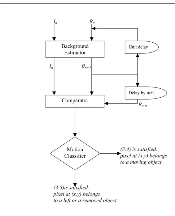
Figure 3.1 is a block diagram illustrating the present invention for characterizing the motion of moving objects in a video consisting of a sequence
CHAPTER 3. MOVING AND LEFT OBJECT DETECTOR 16
of images. The block diagrams and flow diagrams illustrated herein are preferably implemented using software on any suitable general-purpose computer or the like, having microprocessor, memory, and appropriate peripherals, where the software is implemented with program instructions stored on a computer readable medium (memory device, CDROM or DVDROM, magnetic disk, etc.). The block diagrams and methods can alternatively be implemented using hardware (logic gates, etc.) or a combination of hardware and software.
The current image frame In and estimated background image Bn are
input to a background estimating system which determines the next estimate
Bn+1 as described above. This system may have a memory and may use not
only In but also other past frames In-k, k=1,2,… The comparator may simply
take the difference of In and Bn and the difference of Bn+1 and Bn-m to determine
if there is a change in pixel values. Pixels satisfying (3.4) and (3.5) are determined. The motion classifier determines if a pixel belongs to a moving object or a left object. If (3.5) is satisfied at the pixel location (x,y) then the corresponding pixel at (x,y) belongs to a left object. If a pixel at (x,y) satisfies (3.4) but the corresponding background pixel value Bn+1(x,y) does not satisfy
(3.5), this means that this pixel does not belong to a left object. It is the pixel of a moving object in transition in In.
CHAPTER 3. MOVING AND LEFT OBJECT DETECTOR 17 In Bn In Bn+1 Bn-m (3.4) is satisfied:
pixel at (x,y) belongs
to a moving object
(3.5)is satisfied: pixel at (x,y) belongs to a left or a removed object
Background Estimator Motion Classifier Unit delay Delay by m+1 Comparator
Figure 3.1 Block diagram illustrating the proposed system for characterizing the motion of moving regions in an image sequence forming a video by comparing the current image with the background image estimated from the current and past images of the video.
CHAPTER 3. MOVING AND LEFT OBJECT DETECTOR 18
3.2 Detection in Wavelet Domain
Above arguments are valid in compressed data domain as well [6]. In our case, a wavelet transform based coder is used for data compression. The wavelet transform of the background scene can be estimated from the wavelet coefficients of past image frames, which do not change in time, whereas foreground objects and their wavelet coefficients change in time. Such wavelet coefficients belong to the background because the background of the scene is temporally stationary. Non-stationary wavelet coefficients over time correspond to the foreground of the scene and they contain motion information. If the viewing range of the camera is observed for some time, then the wavelet transform of the entire background can be estimated because moving regions and objects occupy only some parts of the scene in a typical image of a video and they disappear over time.
Wavelet transforms have substantial advantages over conventional Fourier transforms for analyzing nonlinear and non-stationary time series because wavelet transform contains both time and frequency information whereas Fourier Transform contains only frequency information of the original signal [9]. These transforms are used in a variety of applications, some of which include data smoothing, data compression, and image reconstruction, among many others. [23] and [7] are examples of image and video coding methods using the wavelet transform. In addition, the so called JPEG2000 image compression standard (ISO/IEC 15444-1:2000) is also based on the wavelet transform. A video consisting of a plurality of images can be encoded using JPEG2000 standard by compressing each image of the video using JPEG2000 standard.
CHAPTER 3. MOVING AND LEFT OBJECT DETECTOR 19
Wavelet transforms such as the Discrete Wavelet Transform (DWT) can process a signal to provide discrete coefficients, and many of these coefficients can be discarded to greatly reduce the amount of information needed to describe the signal. The DWT can be used to reduce the size of an image without losing much of the resolution. For example, for a given image, the DWT of each row can be computed, and all the values in the DWT that are less than a certain threshold can be discarded. Only those DWT coefficients that are above the threshold are saved for each row. When the original image is to be reconstructed, each row can be padded with as many zeros as the number of discarded coefficients, and the inverse Discrete Wavelet Transform (IDWT) can be used to reconstruct each row of the original image. Or, the image can be analyzed at different scales corresponding to various frequency bands, and the original image reconstructed by using only the coefficients that are of a particular band.
Original Image LL(1) LH(1) HL(1) HH(1)
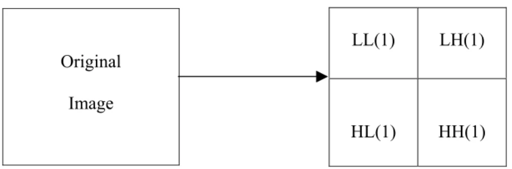
Figure 3.2 Diagrammatic illustration of the transformation of an image into a one-level wavelet transformed image.
Figure 3.2 illustrates the transformation of an original image of the video into a one-level subsampled image. Wavelet transforms can decompose an original image into sub-images in various scales each sub-image representing a frequency subset of the original image. Wavelet transforms use
CHAPTER 3. MOVING AND LEFT OBJECT DETECTOR 20
a bank of filters processing the image pixels to decompose the original image into high-frequency and low-frequency components. This operation can be successively applied to decompose the original image into a low-frequency, various medium-band frequency, and high-frequency components. After each stage of filtering data can be subsampled without losing any information because of the special nature of the wavelet filters. One level of two dimensional dyadic wavelet transform creates four subsampled separate quarters, each containing different sets of information about the image. It is conventional to name the top left quarter Low-Low (LL) – containing low-frequency horizontal and low-low-frequency vertical information; the top right quarter High-Horizontal (HH) or (LH) – containing high-frequency horizontal information; the bottom left quarter High-Vertical (HV) or (HL) – containing high-frequency vertical information; and the bottom right quarter High-Diagonal (HD) or (HH) – containing high-frequency diagonal information. The level of transform is denoted by a number suffix following the two-letter code. For example, LL(1) refers to the first level of transform and denotes the top left corner of the subsampled image by a factor of two in both horizontal and vertical dimensions.
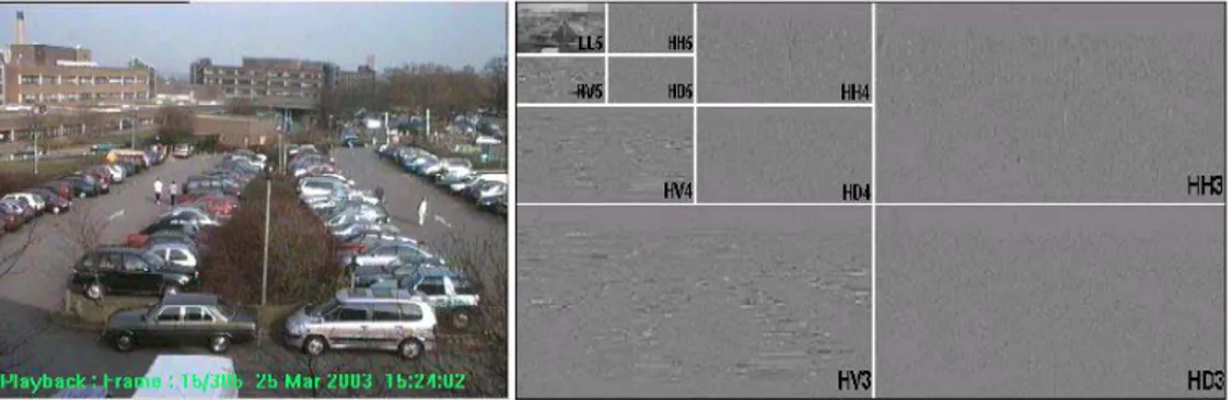
Typically, wavelet transforms are performed for more than one level. For our case, we use up to the fifth level in this study. Figure 3.3 illustrates further transforms that have been performed on the LL quarter of the subsampled image to create additional subsampled images. The second transform performed on the LL(1) quarter produces four second level quarters within the LL(1) quarter which are similar to the first level quarters, where the second level quarters are labeled as LL(2), LH(2), HH(2), and HL(2). A third transform performed on the LL(2) quarter produces four third level quarters labeled as LL(3), LH(3), HH(3), and HL(3), and so on. Additional transforms can be performed to create subsampled images at lower levels.
CHAPTER 3. MOVING AND LEFT OBJECT DETECTOR 21
Figure 3.3: Wavelet transform up to fifth level is performed to the original image on the left. The wavelet transform tree corresponding to the original image, depicting third, fourth and fifth levels is on the right.
A hierarchy of subsampled images from wavelet transforms, such as the three levels of transform shown in Figure 3.3, is also known as a “wavelet transform tree.” A typical three scale discrete wavelet transform (DWT) of the image I is defined as WI = {LL(5), LH(5), HH(5), HL(5), LH(4), HH(4), HL(4), LH(3), HH(3), HL(3)}. The DWT of the image I may be defined to contain LL(3) and LL(4) as well. In fact the so called subband images LL(5), LH(5), HH(5), and HL(5) uniquely define the subband image LL(4), and LL(4), LH(4), HH(4), and HL(4) uniquely define the so called low-low image LL(3).
In wavelet transform based image encoders, many of the small valued wavelet coefficients are discarded to reduce the amount of data to be stored. When the original image is to be reconstructed the discarded coefficients are replaced with zeros. A video is composed of a series of still images (frames) that are displayed to the user one at a time at a specified rate. Video sequences can take up a lot of memory or storage space when stored, and therefore can be compressed so that they can be stored in smaller spaces. In video data compression, each image frame of the video can be compressed using a wavelet coder. In addition, some portions of image frames or entire frames can
CHAPTER 3. MOVING AND LEFT OBJECT DETECTOR 22
be discarded especially when an image frame is positioned between two other frames in which most of the features of these frames remain unchanged.
If the video data is stored in wavelet domain as discussed in the above paragraphs, then the proposed method compares the wavelet coefficients of the subband images corresponding to the current image In, with the wavelet
coefficients of the subband images corresponding to the previous image frame, In-1, to detect motion and moving regions in the current image without
performing an inverse wavelet transform operation. Moving regions and objects can be detected by comparing the wavelet coefficients of the subband image corresponding to the current image with the wavelet coefficients of the subband image corresponding to the background scene Bn which can be
estimated from the subband images of the current and past image frames. If there is a significant difference between the two subband images, then this means that there is motion in the video. If there is no motion, then the wavelet coefficients of the subband image corresponding to the current image, In, and
the background image Bn, ideally should be equal to each other.
The subband image corresponding to the background scene, can be estimated from the wavelet coefficients of past image frames. These coefficients do not change in time, whereas foreground objects and their wavelet coefficients change in time. Such wavelet coefficients belong to the background because background of the scene is temporally stationary. Non-stationary wavelet coefficients over time correspond to the foreground of the scene and they contain motion information. If the viewing range of the camera is observed for some time then the wavelet transform of the entire background can be estimated because moving regions and objects occupy only a portion of the scene in a typical image of a video and they disappear over time.
CHAPTER 3. MOVING AND LEFT OBJECT DETECTOR 23
A simple approach to estimate the wavelet coefficients of the subband image corresponding to the background image, is to average the wavelet coefficients of the observed image frames. Since moving objects and regions occupy only a small portion of the image, they can conceal a part of the background scene and their effect in the wavelet domain is cancelled over time by averaging.
Any one of the space domain approaches for background estimation can be implemented in wavelet domain. For example, the method in [3] reviewed above, can be implemented by simply performing (3.1) for the wavelet coefficients corresponding to the relevant subband images. Let Dn denote a
subband image of the background image Bn at time instant n. Dn may be any
one of the subband images described on page 21 and depicted in Figure 3.3. The estimated subband image of the background for the subband image Dn is
denoted by Dn+1 and calculated as:
n n
n + 1
n
aD (i, j) + (1- a)J (i, j) if (i, j) is non - moving D (i, j) =
D (i, j) if (i, j) is moving
(3.6)
where Jn is the corresponding subband image of the current image frame In.
The update parameter a is a positive real number close to one. Initial subband image of the background, D0, is assigned to be the corresponding subband
image of the first image of the video I0.
In (3.1) - (3.5), (x,y)’s correspond to original image’s pixel locations, whereas in (3.6) and in all the equations in this section, (i,j)’s correspond to locations of subband images’ wavelet coefficients.
CHAPTER 3. MOVING AND LEFT OBJECT DETECTOR 24
A wavelet coefficient at the position (i,j) in a subband image is assumed to be moving if
|Jn (i,j) - Jn-1(i,j)| > Tn(i,j) (3.7)
where Tn(i,j) is a threshold recursively updated for each wavelet coefficient as
follows:
n n n
n + 1
n
aT (i, j) +(1 - a)(b | J (i, j) - D (i, j)|) if (i, j) is non - moving
T =
T (i, j) if (i, j) is moving (i, j)
(3.8)
where b is a real number greater than one and the update parameter a is a positive real number close to one. Initial threshold values can be experimentally determined. As it can be seen from the above equation, the higher the parameter b, higher the threshold or lower the sensitivity of detection scheme.
Estimated subband image of the background is subtracted from the corresponding subband image of the current image to detect the moving wavelet coefficients and consequently moving objects as it is assumed that the regions different from the background are the moving regions. In other words, all of the wavelet coefficients satisfying the inequality
| Jn (i,j) - Dn(i,j)| > Tn(i,j) (3.9)
are determined.
We also compare the subband image of the estimated background for the (n+1)st image, Dn+1 and corresponding subband image of m frame previous
background image, Dn-m to determine the change in background. The duration
parameter m is adjusted by the user to classify if an object is moving or left as discussed before. If there are wavelet coefficients whose values significantly
CHAPTER 3. MOVING AND LEFT OBJECT DETECTOR 25
differ from each other in Dn+1 and Dn-m, then this means that background has
changed. Wavelet coefficients satisfying the inequality:
| Dn+1 (i,j) - Dn-m(i,j)| > Th (3.10)
belong to left or removed objects during the time corresponding to the adjustable duration parameter m. The threshold value Th is a positive integer. Th may be different from the threshold value used in (3.5). It can be also
recursively determined as the threshold used in (3.9).
Once all the wavelet coefficients satisfying the above inequalities are determined and classified accordingly, locations of corresponding regions on the original image are determined. If a single stage Haar wavelet transform is used in data compression then a wavelet coefficient satisfying (3.9) corresponds to a two by two block in the original image frame In. For example,
if (i,j)th coefficient of the subband image HHn(1) (or other subband images HLn(1), LHn(1), LLn (1)) of In satisfies (3.4), then this means that there exists
motion in a two pixel by two pixel region in the original image, In(k,m), k=2x, 2x-1, m=2y, 2y-1 because of the subsampling operation in the discrete wavelet transform computation. Similarly, if the (i,j)th coefficient of the subband image HHn(2) (or other second scale subband images HLn(2), LHn(2), LLn(2)) satisfies
(3.9) then this means that there exists motion in a four pixel by four pixel region in the original image, In(k,m), k=4x, 4x-1, 4x-2, 4x-3 and m=4y, 4y-1, 4y-2, 4y-3. In general a change in the lth level wavelet coefficient corresponds to a 2l by 2l region in the original image.
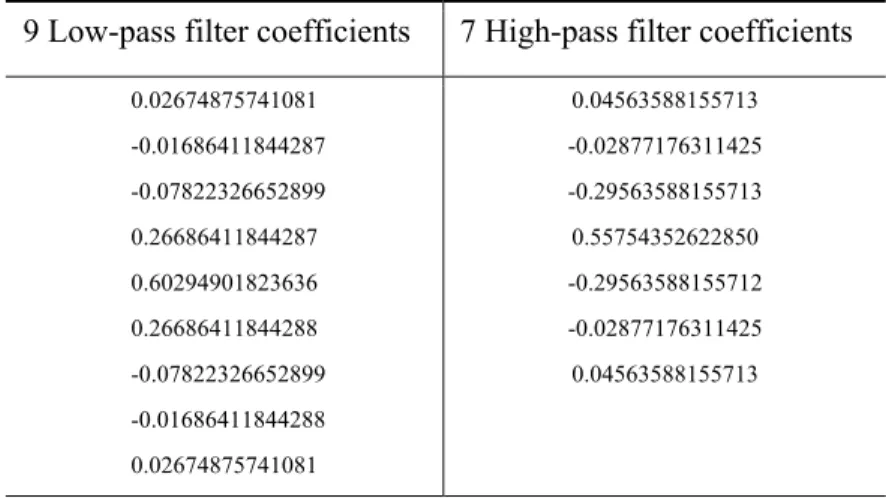
In fact we do not take the wavelet transforms. We feed the compressed data to our system in the format of Aware Inc.’s Motion Wavelet Codec[35]. It uses Daubechies’ 9/7 biorthogonal wavelet [24] whose filter coefficients are
CHAPTER 3. MOVING AND LEFT OBJECT DETECTOR 26
presented at Table 3.1. These coefficients for the analysis part are obtained by applying the factorization scheme presented in [34].
Table 3.1: Lowpass and Highpass filter coefficients
9 Low-pass filter coefficients 7 High-pass filter coefficients
0.02674875741081 -0.01686411844287 -0.07822326652899 0.26686411844287 0.60294901823636 0.26686411844288 -0.07822326652899 -0.01686411844288 0.02674875741081 0.04563588155713 -0.02877176311425 -0.29563588155713 0.55754352622850 -0.29563588155712 -0.02877176311425 0.04563588155713
For this biorthogonal transform, the number of pixels forming a wavelet coefficient is larger than four but most of the contribution comes from the immediate neighborhood of the pixel In(k,m)=(2x,2y) in the first level wavelet
decomposition, and (k,m)=(2lx,2ly) in lth level wavelet decomposition, respectively. Therefore, in this study, we classify the immediate neighborhood of (2x,2y) in a single stage wavelet decomposition or in general (2lx,2ly) in lth level wavelet decomposition as a moving region in the current image frame, respectively.
Once all wavelet coefficients satisfying (3.9) and (3.10) are determined, the union of the corresponding regions on the original image is obtained to locate the moving and left or removed object(s) in the video. The number of moving regions or left objects is equal to the number of disjoint regions obtained as a result of the union operation. The number of the moving and left
CHAPTER 3. MOVING AND LEFT OBJECT DETECTOR 27
object(s) is estimated from the union of the image regions producing the wavelet coefficients satisfying (3.9) and (3.10), respectively.
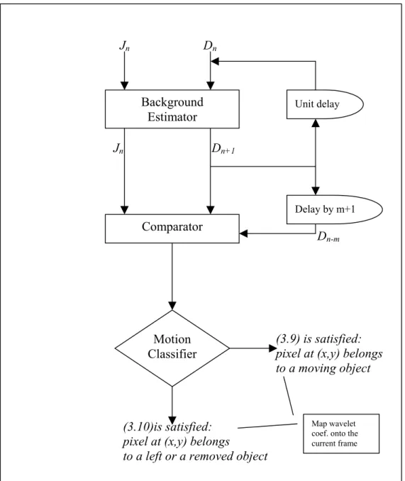
Figure 3.4 is a block diagram illustrating the proposed system for characterizing the motion of moving regions in wavelet compressed video. The Figure 3.4 is similar to the Figure 3.1 except that the operations are carried out in the wavelet domain. Let Jn and Dn be the wavelet transforms of the current
image frame In and estimated background image frame Bn, respectively. The
wavelet transform of the current image Jn and the estimated wavelet transform
of the background scene Dn are input to the background estimator in wavelet
domain. The system implements the above equations to estimate Dn+1. The
comparator may simply take the difference of Jn and Dn and the difference of Dn+1-Dn-m to determine if there is a change in wavelet coefficient values.
Coefficients satisfying (3.9) and (3.10) are determined. The motion classifier determines if a pixel belongs to a moving object or a left object. If (3.10) is satisfied then the corresponding wavelet coefficient Jn(i,j) belongs to a left
object. If a wavelet coefficient Jn(i,j) satisfies (3.9) but the corresponding
background coefficient Dn+1(i,j) does not satisfy (3.10), this means that this
coefficient does not belong to a left object or a removed object. It is the coefficient of a moving object in transition at time n.
CHAPTER 3. MOVING AND LEFT OBJECT DETECTOR 28 Jn Dn Jn Dn+1 Dn-m (3.9) is satisfied:
pixel at (x,y) belongs
to a moving object
(3.10)is satisfied: pixel at (x,y) belongs to a left or a removed object
Background Estimator
Map wavelet coef. onto the current frame Motion Classifier Unit delay Delay by m+1 Comparator
Figure 3.4: A block diagram illustrating the proposed system for characterizing the motion of moving regions in wavelet compressed video by comparing the wavelet transform of the current image with the wavelet transform of background image estimated from the current and past images of the video.
CHAPTER 3. MOVING AND LEFT OBJECT DETECTOR 29
In other transform based methods including the Discrete Cosine Transform (DCT) and Fourier Transform based methods, transform of the background can be estimated as in the case of wavelet transform either by time averaging of the transforms of images forming the video or by recursive estimation as described above or by other means reported in the literature. After estimation of the transform of the background image, (3.4) and (3.5) can be realized in the transform domain to characterize the nature of the motion in video. It should be pointed out that the present system is applicable to the video encoded using internationally standardized coding schemes such as MPEG-1, MPEG-2, MPEG-4 and H261 which are all based on DCT and motion compensated prediction of image frames. In addition, the system can be equally applied to video coded by other linear transforms including the Hadamard transform, Karhunen-Loeve Transform, and vector quantization, etc.
In some image and video coding methods images are divided into blocks and transforms of the blocks are computed. In this case background estimation can be carried out block by block. In addition, a coarse estimate of an image frame can be obtained from the DC value of each block in DCT and Fourier Transform. Therefore a coarse estimate of the background can also be estimated from the DC coefficients of blocks forming the image. For example, if DCT is computed in 8 pixel by 8 pixel blocks, then an image whose height and width are 1/8th of the original image can be estimated from the DC coefficients. Consequently, a coarse background image whose height and width are 1/8th of the actual background image can be estimated from the DC coefficients as well. As described in 3.1, (3.4) and (3.5) can be realized according to the new image size and the motion of moving objects can be characterized.
CHAPTER 3. MOVING AND LEFT OBJECT DETECTOR 30
In vector quantization based image and video coding, blocks forming an image frame are quantized. In this case, background image can be estimated over the quantized image blocks.
A background image can be also estimated from blocks, which do not move or equivalently from blocks whose motion vectors are below a threshold. If the camera capturing the video moves, then the motion of the camera must be compensated to determine the blocks, which do not move. Widely used transforms, DCT and Discrete Fourier Transform are linear transforms, and coefficients obtained after transformation operation can be real or complex number depending on the nature of the transform. Subtraction and addition operations described above for background estimation can be implemented using transform domain coefficients inside blocks in the compressed data domain. In vector quantization, coefficients of the vector quantized blocks are real and they are pixels or pixel-like quantities. Differencing and addition operations described above for background estimation can be implemented using the coefficients of the vector quantized blocks.
3.3 Detection Results and Discussion
We implemented the system explained above with Microsoft Visual C++ 6.0, running on Windows XP, with a Pentium 4 processor. The compressed data fed to our system is in the format of Aware Inc.’s Motion Wavelet Codec[35]. It uses Daubechies’ 9/7 biorthogonal wavelet whose filter coefficients are presented at Table 3.1.
CHAPTER 3. MOVING AND LEFT OBJECT DETECTOR 31
A typical distribution of the detected moving regions are depicted in Figure 3.5. Reddish colored pixels around the walking man are classified as moving after processed with the system proposed in the previous section.
Figure 3.5: Moving pixels detected by the system are shown.
These moving pixels are processed by a region growing algorithm to include the pixels located at immediate neighborhood of them. The immediate neighborhood of a pixel located at (i,j) is shown in Figure 3.6.
(i-1,j-1) (i,j-1) (i+1,j-1)
(i-1,j) (i,j) (i+1,j)
(i-1,j+1) (i,j+1) (i+1,j+1)
CHAPTER 3. MOVING AND LEFT OBJECT DETECTOR 32
The region growing algorithm checks whether the following condition is met for these pixels:
| Jn (i+m,j+m) - Dn(i+m,j+m)| > kTn(i+m,j+m) (3.11)
where m=-1,+1, and 0<k<1, k∈ . If this condition is satisfied, then that particular pixel is also classified as moving. By applying this condition, in a way, we lower the threshold values for neighboring pixels and facilitate the classification of them as moving pixels, thus growing the moving region.
R
After this classification of pixels, moving objects are formed and encapsulated by their minimum bounding boxes. Corresponding boxing of the above object is presented in Figure 3.7. Note that data fed to the system is 720x288 (Figure 3.6), whereas displayed image (Figure 3.7) is 360x270.
Figure 3.7: Minimum bounding box encapsulating the pixels classified as moving.
Making use of different levels of the compression tree and playing with the b parameter in the threshold update equation (3.8), we obtained a
CHAPTER 3. MOVING AND LEFT OBJECT DETECTOR 33
continuum of sensitivity levels. According to the usage of the levels in the compression tree, there are mainly three levels of sensitivities. In the lowest sensitivity level, only the fifth low-low coefficients are used to detect the moving bodies. In the middle sensitivity level, fourth layer’s high subband coefficients are also used. Only the third low-low coefficients are used in order to obtain the highest level of sensitivity for detecting moving regions.
There are a total of one hundred different sensitivity levels among which first thirty-three belong to the lowest level, up to sixty-six belong to medium level and the upper thirty-three to the highest sensitivity level.
Timing comparisons for these three main sensitivities are presented in the Table 3.2. As it can be seen from the table, considering more levels for detection increases the cardinality of the data to be processed, and this consequently increases the time spent per frame for detection.
Table 3.2 : Time performance comparison between three main sensitivity
levels.
Sensitivity 20 60 80
Time to feed the frame (msec.) 0.343 1.171 3.476 Time for detection (msec./frame) 0.985 2.577 9.007 Total Time per frame (msec.) 1.328 3.745 12.483
As it can be seen in the Table 3.2, much of the time spent per frame is for the detection and it increases with increasing sensitivity. Various sequences show similar performance results. Performance comparison of another sequence whose total number of detected objects is less than the one for the
CHAPTER 3. MOVING AND LEFT OBJECT DETECTOR 34
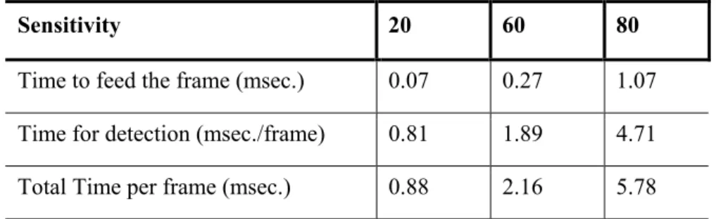
sequence of Table 3.2, is given in Table 3.3. The results presented in Table 3.3 are obtained by using IBM Rational’s Purify Performance Analysis software and figures correspond to the code’s release version.
Table 3.3 : Performance comparison between sensitivity levels for another
sequence.
Sensitivity 20 60 80
Time to feed the frame (msec.) 0.07 0.27 1.07 Time for detection (msec./frame) 0.81 1.89 4.71 Total Time per frame (msec.) 0.88 2.16 5.78
Differences in the figures between sequences’ timing performances result from the difference between total number of detected regions. More regions detected require more calculations. Another reason for the gap between the results especially for the higher sensitivity case is that the analysis corresponding to Table 3.3 is performed for the release code, not the debug version as for Table 3.2.
Chapter 4
Object Tracker
Tracking of the detected objects is the most crucial and the hardest part of a surveillance system [13]. It is crucial because all high level descriptions including activities such as entering, stopping, or exiting scene, are based on the information gained by tracking the moving bodies. It is hard to track objects in video because:
• image changes, such as noise, shadows, light changes, reflection, and clutter, that can obscure object features to mislead tracking,
• the presence of multiple moving objects, especially when objects have similar features, when their paths cross, or when they occlude each other,
• the presence of non-rigid and articulated objects and their non-uniform features,
CHAPTER 4. OBJECT TRACKER 36
• inaccurate object segmentation,
• changing object features, e.g., due to object deformation or scale change,
• application related requirements, such as real-time processing.
Numerous methods for motion analysis and tracking of video objects have been proposed for applications in surveillance systems [5,8,10,15,25-33]. Two strategies can be distinguished among them: one uses correspondence to match objects between successive images and the other performs explicit tracking using a position prediction strategy or motion estimation.
Explicit tracking approaches model occlusion implicitly but have difficulty detecting entering objects without delay and to track multiple objects simultaneously. Furthermore, they assume that object features remain invariant in time. Most of these methods have high computational costs and are not suitable for real-time applications as in our case.
Tracking based on correspondence tracks object, either by estimating their trajectory or by matching their features. In both cases some form of object prediction is used. Prediction techniques incoporated in these methods can be based on Kalman filters or on motion estimation and compensation. The use of a Kalman filter relies on an explicit trajectory model which is difficult in complex scenes and can not be easily generalized. Extended Kalman filters can estimate tracks in some occlusion cases but have difficulty when the number of objects and artifacts increases [10]. Few methods have considered real environments with multiple rigid and/or articulated objects and limited solutions to the occlusion problem exist. In addition, many methods are designed for special applications (e.g., tracking based on body part models or vehicle models) or impose constraints regarding camera or object motion (e.g.,
CHAPTER 4. OBJECT TRACKER 37
upright motion). Many object tracking approaches based on feature extraction assume that the object topology is fixed throughout the image sequence. However in our study, we want to have a moderate tracker to keep track of the detected moving bodies acceptably without any restrictions on the detected objects.
Generalized object tracking and video content understanding are key components in most video surveillance systems that present a compromise between real-time performance and system accuracy. For example, pixel accurate boundary tracking is usually essential for the purposes of video editing. This level of precision has traditionally necessitated extensive or complex models and/or human interaction, thus preventing these approaches from achieving real-time performance. The field of video surveillance, however, is one that often requires robust, but not necessarily pixel accurate, multiple object tracking. Our proposed video surveillance system with its tracker functionality is one such example.
To achieve this kind of real-time performance/system-accuracy balance, we chose to implement our tracker with two easy-to-implement approaches. One is the Voting-Based method presented by Amer [11], and the other is our method of linear-cost-function based scheme. Although we have similar results for both of the methods at high sensitivities, linear-cost-function based approach yielded better and more reliable results.
Voting-based approach has its robustness to changing conditions by spreading the importance of object features and accumulating them in similarity and dissimilarity bins. In this way, loosing the accuracy of a feature at some frame in the sequence does not affect the overall performance of the system much. On the other hand, linear-cost-function based method is much simple to use and more reliable than the voting-based approach. Its simplicity
CHAPTER 4. OBJECT TRACKER 38
comes from the nature of it. It is just a weighted sum of the differences between various features of the current and previous frame objects.
By applying either of the methods, we have a raw matching between the current and previous frame objects. Raw in the sense that, one object belonging to one of the sets (previous frame or current frame) may be assigned to more than one object from the other set. To cope with this over matching problem, some kind of conflict resolution mechanism has to be implemented. For the voting-based scheme, it is correspondence voting that takes care of multiple matching. For the linear-cost-based matching scheme, we model this situation as a minimum cost flow network problem and implemented an algorithm called successive shortest path for the solution of it.
Our method for tracking mainly consists of three steps including the object detection and segmentation phases accomplished by the proposed system presented in Chapter 3: moving object detection and segmentation, object matching and conflict resolution as shown in Figure 4.1.
CHAPTER 4. OBJECT TRACKER 39 In In-1 Step 1 Feedback & On On-1 Update Step 2 Step 3 Object Trajectory Moving Object Detection
and Segmentation
Object Matching (Occlusion Handling) (Stopped Object Decision)
Conflict Resolution
Figure 4.1: Framework of the tracker. Current, In, and previous, In-1, frames are
fed into the detection part producing the current, On, and previous, On-1,
CHAPTER 4. OBJECT TRACKER 40
The framework for the tracker is the same for both types of approaches. The difference between them is in the implementations of Step 2 and Step 3. Object matching is achieved by object voting in the voting based approach, whereas objects are matched to each other considering linear-cost-function values corresponding to them in the other method. For conflict resolution step, linear-cost-function based method uses a successive shortest path algorithm. Correspondence voting is the alternative for the voting scheme as conflict resolver.
Tracking is activated once an object enters the scene. An entering object is immediately detected by the detection module. Then the segmentation module extracts the relevant features for the matching (correspondence) module. While tracking objects, the segmentation module keeps looking for new objects entering the scene. Once an object is in the scene, it is assigned a new trajectory. Objects that have no correspondence are assumed to be new, entering or appearing, and are assigned new trajectory. Segmentation results from the first step are subject to change with the occlusion handling and stopped object decision parts of the second step. Consequently, an update may be required for re-segmenting the moving regions into moving objects. After conflict resolution, the trajectories of the objects are decided and updated accordingly.
Step 1 in the tracker module mainly assigns selected features of objects. The features are listed and explained in 4.1. After feature selection, at Step 2 these features are integrated based on voting or linear cost function to realize the matching between the objects of previous and current frames. Detailed explanations are given in 4.2 and 4.3. Occluding and occluded objects are also determined at this step and action is taken for these object pairs. Slowing and stopped objects are marked using a similar method to the one described for left
CHAPTER 4. OBJECT TRACKER 41
object detection in 3.2. Results of the tests and comparisons between these two trackers are presented in 4.6.
4.1 Features for Tracking
In the first step, spatio-temporal object features or descriptors are extracted and selected. The implemented descriptors are simple but efficient when combined. In the following, let Oi represent an object of the current image In
and Op an object in the previous image In-1.
• Size: the size is described by the area Ai of the object Oi, width Wi (i.e.,
the maximum horizontal extent of Oi), and height Hi (i.e., the maximum
vertical extent of Oi).
• Shape: the following descriptors are used
1. Minimum bounding box (MBB) BOi : the MBB of an object is the
smallest rectangle that includes the object; 2. Extent ratio: ei = Hi/Wi
• Motion: object motion is described by the current displacement vector wi = (wx; wy) of Oi.
• Distance: the Euclidean distance between the centroid of an object Oi of In and an object Op of In-1.
• Brightness: minimum, maximum and average brightness values of the current frame objects are assigned. For a current frame object Oi, these values are mbi, Mbi, abi,
CHAPTER 4. OBJECT TRACKER 42
values are set from the corresponding fifth low-low wavelet coefficients.
These descriptive features form the basis for matching. This much feature has turned out to be enough for reaching the goal of having a general tracker. More descriptive attributes may be assigned to objects, like features exploiting color information, in order to have a more sophisticated surveillance system that is to be used for behavioral analysis for example.
4.2 Voting Based Scheme
In the voting based matching, spatial and temporal features are combined using a non-linear scheme consisting of two steps: voting for object features of two objects (object voting) and voting for features of two correspondences in the case one object is matched to two objects (correspondence voting).
Each voting step is first divided into m sub-votes v1, v2, …vm with m
object features. Since features can become harmful or occluded, the value m varies spatially (objects) and temporally (throughout the image sequence) depending on a spatial and temporal filtering. This means that, at various frames, various features are voted. Then each sub-vote, vi, is performed
separately using an appropriate voting function.
A voting function basically compares a feature of an object pair Oi-Op,
where Oi is an object of the current frame and Op is an object of the previous
frame. According to this comparison, either a similarity variable s or a non-similarity variable d is increased. Depending on the number of features in a sub-vote, vi, s or d may increase by one or more.