Abstract
The PI Controller can be considered as the essential part for efficient Speed Control of the Interior Permanent Magnet Synchronous Motor. In digital control, two platforms exist to implement this controller, namely DSP and FPGA. The FPGA is more preferred than the DSP due to the concurrent facility. To obtain the full facilities of the digital control and for high accuracy speed control of motors, floating point PI Controller should be used instead of the fixed point. The problem of the FPGA is that it is programmed using VHDL or Verilog which deals only with fixed-point representation. This paper shows a full design of floating-point PI Controller using Altera DE2i-150 platform and Altera Megafunctions. The results are proven using two simulation platforms ModelSim-Altera Starter Edition 15.0 and Matlab Simulink.
Keywords: FPGA, IPMSM, PI Controller, SVPWM.
FPGA ILE IPMSM HIZ KONTROLÜ IÇIN KAYAN NOKTALI PI AKIM DENETLEYICI TASARIMI
Özet
PI Denetleyici, Dahili Sürekli Mıknatıslı Senkron Motor (DSMSM)’un hız kontrolünün verimli şekilde gerçekleştirilmesinin önemli bir parçası olarak ele alınabilir. Sayısal kontrolde bu denetleyicinin gerçekleştirilmesi için DSP ve FPGA olmak üzere iki platform mevcuttur. FPGA, eşzamanlı işlem özelliğinden dolayı DSP’ye göre daha fazla tercih edilir. Sayısal kontrolün tüm özelliklerinden faydalanılması ve motorların hız kontrolünün yüksek doğrulukta elde edilmesi için sabit noktalı yerine kayan noktalı PI denetleyici kullanılmalıdır. FPGA’de karşılaşılan problem sadece sabit noktalı sayılarla
+ This paper has been presented at the ICENTE'17 (International Conference on Engineering Technologies)
held in Konya (Turkey), December 07-08, 2017.
DESIGN OF FLOATING POINT PI CURRENT CONTROLLER FOR SPEED CONTROL OF IPMSM USING FPGA
Abdulhasan ALTAEY1,+ Ahmet Afşin KULAKSIZ2
1 Ph.D. Student in Selcuk University, Konya/Turkey, Instructor in the University of Mustansiriyah, Baghdad, Iraq [email protected]
işlem yapılan VHDL veya Verilog kullanılarak programlanmasıdır. Bu makale, Altera DE2i-150 platformu ve Altera Megafunctions kullanılarak kayan noktalı PI denetleyicinin komple tasarımını göstermektedir. Sonuçlar, ModelSim-Altera Starter Edition 15.0 ve Matlab Simulink olmak üzere iki benzetim platformunda doğrulanmıştır. Anahtar Kelimeler: FPGA, IPMSM, PI Denetleyici, SVPWM.
1. Introduction
The advanced features of the Interior Permanent Magnet Synchronous Motors
(IPMSMs) such as high efficiency, high torque to inertia have been made them used in a lot of applications. To achieve these features, it is necessary to use high performance controller. The previous works [1-4] proved the reliability and stability of systems, which used PI Controllers. The implementation of these controllers is either analog or digital. For more accurate results, the digital approach is more preferable. In general, to implement these controllers, microprocessor, microcontroller or DSP as well as software have been used [5-8]. The disadvantage of these methods is the long time required to compile and execute the software instructions. The other possible platform for control strategy is the FPGA. The current trend in literature shows that FPGA is more preferable than DSP because the FPGA is clock-based which means faster processing capability compared to instruction based (DSP). Also, the FPGA has the facility of concurrent operation which will reduce the processing time a lot.
The FPGA can be programmed using the VHDL or the Verilog. Both of these hardware languages deal only with fixed-point representation while precise speed control of motors requires PI Controller with floating-point processing. To alleviate this problem ALTERA has provided IP Cores dealing with this floating-point representation. Some of these IP Cores are free and some require a license. Building the PI Controller using FPGA requires mix using of VHDL or Verilog and the IP Cores. All the IP Cores Megafunctions are clock-based. Each IP require some number of clock cycles to obtain the result. Hence the processes that work in parallel will have different execution times. As an example, if the sampling time is 100us, clock cycle period is 20 ns and as the floating point adder, IP Core requires 7 cycles that means the adding process will be repeated by (100000)/(7*20) in each sampling time. To solve this problem each process should have a synchronizing
process using VHDL or Verilog to ensure the processes are not repeated during one sampling time.
The previous problems and for other problems such as the limited availability of the hardware sources of the FPGA platform make the researchers prefer to use fixed-point PI Controller rather than floating-point at the expense of losing the accuracy. This paper uses a mixed design of VHDL and ALTERA IP Core Megafunctions to design a floating-point PI Controller for Speed Control of the IPMSMs. Firstly discrete time equations are derived, then the PI parameters are designed using the Root-Locus method. A simulation package of the Electronic Design Automation (EDA) can be used to verify the algorithms that have been built using FPGA. This EDA simulator provides a verification interface between MATLAB Simulink and FPGA board. This paper uses the ModelSim-ALTERA Starter Edition 15.0 and MATLAB SIMULINK to prove the results. The results of both simulations are exactly the same which proves the design.
2. Discrete time design
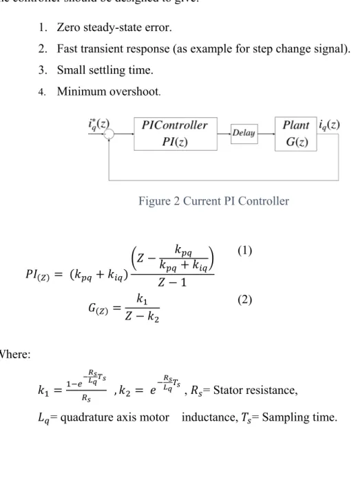
Figure 1 shows a general description of the whole system of speed control of the IPMSM. According to the difference between the reference and measured speed, the Speed PI Controller Commands the proposed current values to the Current PI Controller. The Current PI controller receives these proposed values as well as it receives the measured current values. According to the error between the commanded and measured values, the Current PI Controller will command the required voltage values to the motor. According to the commanded voltage values (vd_proposed, vq_proposed), Space Vector Pulse Width Modulation Signals (SVPWM) will be constructed to drive the motor (not shown in Figure 1). The PI Controller process time should be finished within the dead time width of the SVPWM signals. As it is clear from Figure 1 that the motor is decoupled to two axes, namely d-axis and q-axis. The following derivations are for the q-axis and in the same way it can be done for the d-axis.
Figure 1 Speed Control Loop
The PI controller for the q-axis current is shown in Figure 2. Using Root Locus Method, the controller should be designed to give:
1. Zero steady-state error.
2. Fast transient response (as example for step change signal). 3. Small settling time.
4. Minimum overshoot.
Figure 2 Current PI Controller
1 (1) (2) Where: , , = Stator resistance,
∗ 1 1 (3)
The closed loop poles are determined from the characteristics equation:
1 0 (4)
Where K is the closed loop gain and equals:
1
(5)
1 (6)
(7)
The value of the gain K is obtained from the root locus, and ωc is the crossover frequency of the open loop transfer function GOL-. The root locus starts from the open loop (GOL-):
(8)
1
(9)
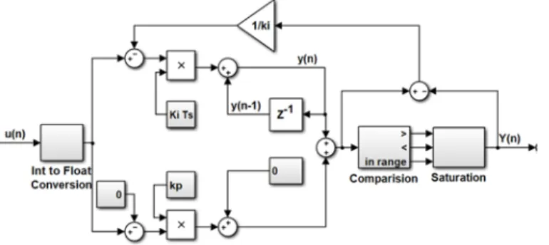
The technical data of the motor used in this paper is shown in Table 1. The motor electric pole at Z=k2 has a time constant of (Lq/Rs=14.2 ms). This long time constant can degrade the system response. To solve this problem, the zero at is chosen to cancel this pole, hence (9) resolves to:
1
1
(10)
The root locus is shown in Figure 3. The closed loop pole is chosen to give damping ratio of 0.947, overshoot = %0.0093 and the natural frequency is 7050Hz. The total gain is 0.263. The proportional and integral constants of the q-axis PI Controller solved as follows: 1. 0.993. 2. 0.263 . 3. 0.00195. 4. Hence: . . 134.87. 5. 0.993 133.9. 6. 0.97.
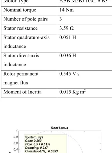
Table 1 IPMSM Technical Data.
Motor Type ABB M2BJ 100L 6 B3 Nominal torque 14 Nm
Number of pole pairs 3 Stator resistance 3.59 Ω Stator quadrature-axis inductance 0.051 H Stator direct-axis inductance 0.036 H Rotor permanent magnet flux 0.545 V s Moment of Inertia 0.015 Kg m2
Figure 3 q-axis Current Controller Root Locus
Applying these values in (3):
∗
0.263 0.263
The step response of (11) shown in Figure 4 demonstrates that the settling time is 0.797 ms, which proves the controller stability. The same procedure can be used for the d-axis PI Current controller.
Figure 4 q-axis Step Response
3. FPGA Design
Field Programmable Gate Array (FPGA) is low cost device with the capability of concurrent processes which is very important in applications that require parallel processing. In most cases, the development of high performance control of the IPMSM needs FPGA with embedded processor IP (Intellectual Property) and an application IP [9][13-16]. The former is implemented by using software due to the complicated control algorithms, and the latter is implemented by hardware due to simple computation which may contain parallel computation. SVPWM is an essential part of speed control process. For an efficient system, the control process should be finalized in the dead time of the SVPWM. These SVPWM signals have been implemented using VHDL on ALTERA FPGA DE2i-150 as shown in Figure 5. This dead time requirement is achieved by PI controller as hardware. One of the essential parts of the discrete PI Controller is the integrator shown in Figure 6, where:
Figure 5 SVPWM Signals Using Altera DE2i-150
Figure 6 Back Euler Integrator.
After some simplifications, Equation (12) can be written as (13).
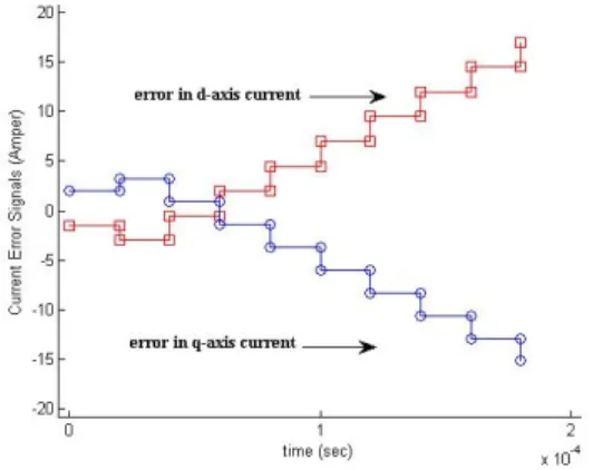
According to these equations, the discrete PI Controller can be constructed. The current PI Controller output value is the commanded voltage of the IPMSM motor. The commanded value should not exceed the rating values. Hence anti-winding circuit [10-12] should be added to ensure that the rating values are not exceeded. To keep the precision, floating point representation is used for this PI Controller. All the mathematical operations (addition, subtraction, multiplication etc.) are done using the floating point ALTERA IP Cores. These IP Cores require different number of clock cycles to process its job. One important issue in the FPGA design is to make the signals (which is added or multiplied…) arrives at the same time. Otherwise wrong results will be obtained. To balance these paths, some part should be added as shown in Figure 7. Instead of adding parts, a better solution exists that is by adding some algorithms similar to sample and hold. These algorithms can be written using VHDL only. According to the last discussion, the PI controller has been built using ALTERA DE2i-150 as shown in the next section.
Figure 7 Balanced Path Floating Point Discrete PI Controller with Anti-Windup.
4. Simulation (Quartus & MATLAB) Comparative Study
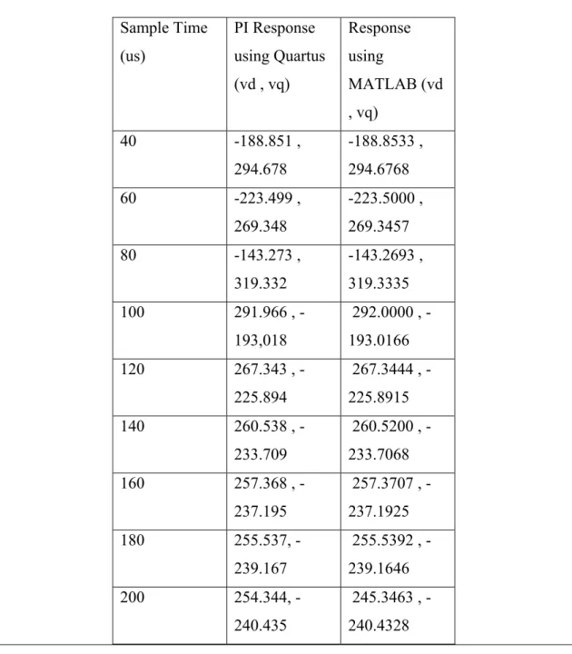
The response to two types of input signals: constant-input (Figure 8) and variable-input (Figure 9) are studied. Two types of simulations have been done. The first simulation has been done to the floating-point PI Controller shown in Figure 10 using Model-Sim ALTERA STARTER EDITION 15.0. The response to the constant-input signals is shown in Figure 11 and the response to the variable-input signals is shown in Figure 12. The second simulation has been done using MATLAB SIMULINK. The response to the constant-input signals is shown in Figure 13 and the response to the variable-input signals is shown in Figure 14. Before doing comparison between these two simulations, it should be known that FPGA needs reset pulse and some delays to keep the synchronizing. Hence, the FPGA needs one sampling time delay before giving the response. Taking this note into consideration, a comparison between these simulation results is shown in Table 2. The two simulation results are coincident 100% which prove the validity of the design method. This paper is a part of Ph. D. thesis, and a plan exists to apply this design experimentally.
5. Conclusion
This paper proposes a full design for floating point Discrete PI Controller for Speed Control of IPMSM using FPGA. The paper proposed to use a hybrid algorithm of VHDL which only fixed point and floating point ALTERA megafunctions (IP) Cores. The design of the Discrete PI Controller parameters has been carried out using Root Locus Method. Two Simulations have been done, one using Model-Sim ALTERA STARTER EDITION
15 and the other using MATLAB SIMULINK. The two simulation results are coincident 100% which validates the design.
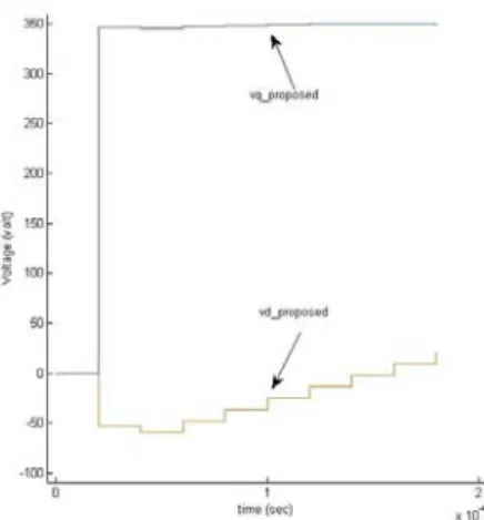
Figure 8 Constant Error Signals iq and id.
Figure 10 Final Floating Point Current PI Controller constructed using ALTERA Megafunctions and VHDL.
Figure 11 Simulation Results to constant-input signals Using ModelSim-ALTERA
EDITION 15.0.
Figure 12 Simulation Results to variable-input signals Using ModelSim-ALTERA
EDITION 15.0.
Figure 13 Simulation Results to constant-input signals Using MATLAB.
Table 2 Comparison between PI Controller Responses using Quartus and MATLAB Sample Time (us) PI Response using Quartus (vd , vq) Response using MATLAB (vd , vq) 40 -188.851 , 294.678 -188.8533 , 294.6768 60 -223.499 , 269.348 -223.5000 , 269.3457 80 -143.273 , 319.332 -143.2693 , 319.3335 100 291.966 , -193,018 292.0000 , -193.0166 120 267.343 , -225.894 267.3444 , -225.8915 140 260.538 , -233.709 260.5200 , -233.7068 160 257.368 , -237.195 257.3707 , -237.1925 180 255.537, -239.167 255.5392 , -239.1646 200 254.344, -240.435 245.3463 , -240.4328 References
[1]. Kannan, R., Gayathri, N., Natarajan, M., Sankarkumar, R., Iyer, L., and Kar,N., 2016, Selection of PI controller tuning parameters for speed control of PMSM using Biogeography Based Optimization algorithm, IEEE International Conference
on Power Electronics, Drives and Energy Systems (PEDES), Trivandrum, pp. 1-6.
doi: 10.1109/PEDES.2016.7914260.
URL: http://ieeexplore.ieee.org/stamp/stamp.jsp?tp=&arnumber=7914260&isnumb er=7914213/
[2]. Li, C., Chen, M., and Gao, S., 2014, Fractional order PI speed control for permanent magnet synchronous motor drives, Proceeding of the 11th World
Congress on Intelligent Control and Automation, Shenyang, pp. 4681-4685.
doi: 10.1109/WCICA.2014.7053504.
URL: http://ieeexplore.ieee.org/stamp/stamp.jsp?tp=&arnumber=7053504&isnumb er=7052676.
[3]. Khater, F., Shaltout, A., Hendawi, E., and Abu El-sebah, M., 2009, PI controller based on genetic algorithm for PMSM drive system, IEEE International
Symposium on Industrial Electronics, Seoul, pp. 250-255.
doi: 10.1109/ISIE.2009.5217925
URL: http://ieeexplore.ieee.org/stamp/stamp.jsp?tp=&arnumber=5217925&isnumb er=5213059.
[4]. Ranjith Kumar, G., Arun Noyal Doss, M., Prasad, K., and Jayasankar, K., 2011, Modeling and speed control of permanent magnet synchronous Motor at constant load torque using PSIM, International Conference on Sustainable Energy and
Intelligent Systems (SEISCON 2011), Chennai, pp. 485-489.
doi: 10.1049/cp.2011.0411.
URL: http://ieeexplore.ieee.org/stamp/stamp.jsp?tp=&arnumber=6143359&isnumb er=6143272.
[5]. Kung, Y., et al. Design and Implementation of a Microprocessor-Based PI Controller for PMSM Drives, Applied Mechanics and Materials 2015, Vols. 764-765, pp. 496-500.
[6]. Yang, Ming, Niu, L., and XU, D. Antiwindup design for the speed loop PI controller of a PMSM servo system, Turkish Journal of Electrical Engineering &
Computer Sciences 21.5 (2013): 1318-1327.
[7]. Li, L., 2014,DSP based digital control system implementation of permanent magnet synchronous motor, The 26th Chinese Control and Decision Conference
(2014 CCDC), Changsha, pp. 3527-3531.
doi: 10.1109/CCDC.2014.6852790.
URL: http://ieeexplore.ieee.org/stamp/stamp.jsp?tp=&arnumber=6852790&isnumb er=6852105.
[8]. Tariq, Mohd, et al. Fast response Antiwindup PI speed controller of Brushless DC motor drive: Modeling, simulation and implementation on DSP, Journal of
Electrical Systems and Information Technology 3.1 (2016): 1-13.
[9]. Kung, Y., Chen, C., Wong, K., and Tsai, M., 2005, Development of a FPGA-based control IC for PMSM drive with adaptive fuzzy control, 31st Annual Conference of
IEEE Industrial Electronics Society, IECON 2005., pp. 6 pp.-.
doi: 10.1109/IECON.2005.1569134.
URL: http://ieeexplore.ieee.org/stamp/stamp.jsp?tp=&arnumber=1569134&isnumb er=33243.
[10]. Perera, P., Sensorless control of permanent-magnet synchronous motor drives. PhD thesis, AALBORG UNIVERSITY AALBORG, 2002.
[11]. Espina, J., Arias, A., Balcells, J., and Ortega, C., 2009, Speed Anti-Windup PI strategies review for Field Oriented Control of Permanent Magnet Synchronous Machines, 2009 Compatibility and Power Electronics, Badajoz, pp. 279-285. doi:
10.1109/CPE.2009.5156047 URL:
http://ieeexplore.ieee.org/stamp/stamp.jsp?tp=&arnumber=5156047&isnumber=51 55997.
[12]. Klinlaor, K., and Chuladaycha, N., 2012, Improved speed control using Anti-Windup PI controller for Direct Torque Control based on permanent magnet synchronous motor, 2012 12th International Conference on Control, Automation and Systems, JeJu Island, pp. 779-783. URL:
http://ieeexplore.ieee.org/stamp/stamp.jsp?tp=&arnumber=6393288&isnumber=6 393028.
[13]. Marufuzzaman, M., Reaz, M., and Ali, M., 2010, FPGA implementation of an intelligent current dq PI controller for FOC PMSM drive, 2010 International Conference on Computer Applications and Industrial Electronics, Kuala Lumpur, pp. 602-605. doi: 10.1109/ICCAIE.2010.5735005. URL:
http://ieeexplore.ieee.org/stamp/stamp.jsp?tp=&arnumber=5735005&isnumber=5 735003.
[14]. Maragliano, G., Marchesoni, M., and Vaccaro, L., 2010, FPGA implementation of a sensorless PMSM drive control algorithm based on algebraic method, 2010 IEEE International Symposium on Industrial Electronics, Bari, pp. 3083-3088. doi: 10.1109/ISIE.2010.5637857. URL:
http://ieeexplore.ieee.org/stamp/stamp.jsp?tp=&arnumber=5637857&isnumber=5 635477.
[15]. Khanh, Q., That, N., Hong, Q., and Ha, Q., 2012, FPGA-based fuzzy sliding mode control for sensorless PMSM drive, 2012 IEEE International Conference on Automation Science and Engineering (CASE), Seoul, pp. 172-177. doi:
10.1109/CoASE.2012.6386449. URL:
http://ieeexplore.ieee.org/stamp/stamp.jsp?tp=&arnumber=6386449&isnumber=6 386304.
[16]. Amornwongpeeti, Sarayut, et al., 2015, A single chip FPGA-based solution for controlling of multi-unit PMSM motor with time-division multiplexing scheme., Microprocessors and Microsystems 39.8 (2015), pp. 621-633.