KADIR HAS UNIVERSITY
GRADUATE SCHOOL OF SCIENCE AND ENGINEERING
NEW CHANNEL ESTIMATION TECHNIQUES FOR COOPERATIVE UNDERWATER ACOUSTIC OFDM SYSTEMS
Master Thesis
Mustafa ERDOĞAN
Must afa ERDOĞ A N M.S . The sis 2013 S tudent’ s F ull Na me P h.D. (or M.S . or M.A .) The sis 20 11
NEW CHANNEL ESTIMATION TECHNIQUES FOR COOPERATIVE UNDERWATER ACOUSTIC OFDM SYSTEMS
Mustafa ERDOĞAN
Submitted to the Graduate School of Kadir Has University in partial fulfillment of the requirements for the degree of
Master of Science in
Electronics Engineering
KADIR HAS UNIVERSITY May, 2013
KADIR HAS UNIVERSITY GRADUATE SCHOOL OF SCIENCE AND ENGINEERING
NEW CHANNEL ESTIMATION TECHNIQUES FOR COOPERATIVE UNDERWATER ACOUSTIC OFDM SYSTEMS
MUSTAFA ERDOĞAN
APPROVED BY:
Prof. Dr. Erdal Panayırcı
Asst. Prof. Dr. Habib Şenol
Prof. Dr. Hakan Ali Çırpan
APPROVAL DATE: 02/05/2013 AP PE ND IX C APPENDIX B APPENDIX B
i
NEW CHANNEL ESTIMATION TECHNIQUES FOR COOPERATIVE UNDERWATER ACOUSTIC OFDM SYSTEMS
Abstract
Cooperative underwater acoustic communication systems come into prominence in recent years. Since underwater channels are sparse and additive noise entering the system is colored Gaussian noise, it is very difficult to estimate the underwater channels and theoretically makes it interesting. In the first part of the thesis, the transmission from source to the target recipient is realized by means of a relay system. Orthogonal frequency division multiplexing (OFDM)-based channel estimation problem is solved by using the matching pursuit (MP) algorithm and we obtained excellent error performance. In the second part of the thesis, an efficient channel estimation algorithm is purposed for amplify-and-forward (AF) cooperative relay based OFDM system in the presence of sparse underwater acoustic channels and of the correlative non-Gaussian noise. The algorithm is based on the combinations of the MP and the space-alternating generalized expectation-maximization (SAGE) technique , to improve the estimates of the channel taps and their location as well as the Gaussian mixture noise distribution parameters in an iterative way. Computer simulations show that underwater acoustic channel is estimated very effectively and the proposed algorithm has excellent symbol error rate (SER) and channel estimation performance, as compared to the existing ones.
ii
SUALTI İŞBİRLİKLİ AKUSTİK OFDM SİSTEMLERİ İÇİN YENİ KANAL KESTİRİM TEKNİKLERİ
Özet
İşbirlikli sualtı kablosuz iletişim sistemleri konusu son yıllarda büyük önem kazanmıştır. Özellikle sualtı akustik kanalların seyrek olma özelliği taşıması ve sisteme giren toplamsal gürültünün renkli Gauss gürültüsü olması sualtı kanallarının kestirimini çok zorlaştırmaktadır ve kuramsal açıdan ilginç kılmaktadır. Bu tezin ilk kısmında, kaynaktan hedef alıcıya iletimin röle aracılığıyla yapıldığı bir dik frekans bölmeli çoğullama (orthogonal frequency division multiplexing (OFDM))-tabanlı sisteme uyumlu eşleme (matching pursuit (MP)) algoritması kullanılarak kanal kestirim problem çözülmüş ve elde edilen sonuçlarda yüksek hata başarım elde edilmiştir. Tezin ikinci kısmında, seyrek yapıdaki sualtı akustik kanallar üzerinden çalışan güçlendir-ve-aktar (AF) işbirlikli röle tabanlı OFDM sistemler için özgün ve yeni bir kanal kestirim algoritması önerilmektedir. Hesaplama karmaşıklığı düşük, hızlı, ve iteratif yapıdaki bu algoritma, uyumlu eşleme (MP) ve genelleştirilmiş beklenti enbüyükleme (SAGE) tekniklerinin birleştirilmesine dayanmaktadır. Algoritma gerek seyrek yapıda sualtı kanalın çok yollu kanal katsayılarını ve bunların konumlarını kestirmekte ve gerekse kanalı etkileyen ve bir Gauss karışımı ile modellenen, Gauss olmayan gürültünün karışım parametrelerini belirlemektedir. Yapılan bilgisayar benzetimleri, önerilen kanal kestirim algoritmasının simge hata ve kestirim algoritmalarına oranla çok daha iyi sonuçlar verdiğini göstermektedir.
iii
Acknowledgements
I would like to express my deep-felt gratitude to my advisor, Prof. Dr. Erdal Panayırcı, the head of Electronic Engineering Department at Kadir Has University, for his constant motivation, support, expert guidance, constant supervision and constructive suggestion for the submission of my thesis work. He was never ceasing in his belief in me, always providing clear explanations when I was lost, and always giving me his time. I wish all students would have an opportunity to experience his ability.
I also wish to thank Dr. Habib Şenol of the Computer Engineering Department at Kadir Has University. His suggestions and comments were invaluable to the completion of this work. He was extremely helpful in providing the additional guidance and expertise. I needed, especially with regard to the chapter on estimation of multipath channel between source and relay nodes.
Words cannot express my heartiest thanks and gratitude to my parents for their unconditional love, support and encouragement throughout this work.
This study was supported by the TUBITAK project. Grant No: 110E092. AP
PE ND IX C
iv
Table of Contents
Abstract ………... i Özet ……….. ii Acknowledgements .……… iii Table of Contents ………... iv List of Tables ……….. viList of Figures .………... vii
List of Symbols ……….. viii
List of Abbreviations ..………... ix
Chapter 1 Introduction ………. 1
1.1 Background ……….. 1
1.2 UWA Communications ……… 2
1.2.1 Early Research Efforts ………. 2
1.2.2 Digital UWA Communications ……… 3
1.2.3 Current Research Efforts and Future Ahead ………. 3
1.3 Cooperative UWA Communications ………... 4
1.3.1 Cooperative Diversity …………...…...……….... 6
1.3.2 OFDM-based Cooperative Communication ……….. 6
1.4 Channel Estimation …………..……….. 7
1.5 Objectives and Outline of Thesis ……… 7
2 UWA Channel Model ……….... 9
2.1 Introduction ……… 9
2.2 Basic Characteristics of UWA Channel Model ………. 9
2.2.1 Propagation Delay ………. 9 2.2.2 Transmission Loss ………. 10 2.2.3 Fading ……… 11 AP PE ND IX C
v
2.2.4 Noise ……….. 12
2.3 OFDM Overview ……….. 13
3 Estimation of Multipath Channel between Source and Relay Nodes 15
3.1 Introduction ………. 15
3.2 System Model ………... 15
3.3 Channel Estimation between Source and Destination ….……... 20
3.4 Channel Estimation between Source, Relay and Destination …….... 22
3.4.1 Estimation of , ……….. 24
3.4.2 Estimation of …………. 27
3.4.3 Initialization of the Algorithm ……… 30
4 Simulation Results ……….………... 32
4.1 Performance of Channel Estimation between Source and Destination 32
4.2 Performance of Channel Estimation between Source, Relay and Destination ……….………. 34 5 Conclusions ………... 37 References ………... 38 Curriculum Vitae ……….……… 44 AP PE ND IX C APPENDIX B
vi
List of Tables
Table 4.1 Simulation parameters for performance of channel estimation between source and destination (S-D) ... 29
Table 4.2 Simulation parameters for performance of channel estimation between source, relay and destination (S-R-D) ... 31
vii
List of Figures
2.1 Underwater OFDM system block diagram ……… 13
3.1 Single-relay transmission model………... 16
3.2 Pilot Scheme of the UWA-OFDM system ……… 18
4.1 MP channel estimation for MSE performance ……….. 30
4.2 Under the channel estimation with the assumption that the channel is known perfectly SER performance comparison………... 30
4.3 SER performance of the MP-SAGE and MP-BLUE algorithms ………. 32
4.4 SER performance of the MP-SAGE algorithm under the effects of Doppler mismatch ……….. 33
viii
List of Symbols
T : Temperature S : Salinity z : Depth : Absorption coefficient : Range: Spreading loss factor : Turbulence Noise : Shipping Noise : Wind Noise : Thermal Noise : Shipping Factor : Speed of wind : Frequency : Ambient Noise : Mean : Variance : Source : Relay : Destination
: Complex Gaussian random variable : Colored noise autocorrelation function
: Sampling period : Normalization factor : FFT matrix
: Diagonal matrix
ix
: SVD of the covariance matrix
: N×N complex valued unitary transformation matrix : N×N diagonal matrix with positive real entries : Conjugate transpose operator
: White noise : Pilot number
: Residual vector
: Estimates for an unknown parameter : Hidden data
: Observed Signal
x
Abbreviations
AF : Amplify-and-Forward
OFDM : Orthogonal Frequency Division Multiplexing MP : Matching Pursuit
SAGE : Space-Alternating Generalized Expectation EM : Expectation-Maximization
SER : Symbol Error Rate RF : Radio Frequency UWA : Underwater Acoustic
SSB-SC : Single-Side Band Suppressed Carrier DSP : Digital Signal Processing
VLSI : Very Large Scale Integration PSK : Phase Shift-Keying
QAM : Quadrature Amplitude Modulation FSK : Frequency Shift-Keying
ML : Maximum Likelihood
DFE : Decision Feedback Equalizer RLS : Recursive Least Squares PLL : Phase-Locked Loop
AWGN : Additive White Gaussian Noise TDMA : Time Division Multiple Access TD : Transmit Diversity
RD : Receive Diversity
STD : Simplified Transmit Diversity DF : Decode-and-Forward
CRC : Cyclic Redundancy Check CSI : Channel State Information
xi
PAPR : Peak-to-Average-Power Ratio FG : Francois-Garrison
ISI : Inter-Symbol Interference SVD : Singular Value Decomposition BPSK : Binary Phase Shift-Keying QPSK : Quadrature Phase Shift Keying MSE : Minimum Square Error
BLUE : Best Linear Unbiased Estimator
1
Chapter 1
Introduction
1.1 Background
Underwater wireless communication has received a growing attention and research has been active for over a decade on designing the methods for underwater applications. It has been of critical importance to provide high-speed wireless links with high link reliability in various underwater applications such as offshore oil field exploration/monitoring, oceanographic data collection, maritime archaeology, seismic observations, environmental monitoring, port and border security among many others. Although wire-line systems have been used to provide real-time communication in some underwater applications, their high cost and operational disadvantages become restrictive for many cases. Wireless communication is a promising alternative and an ideal transmission solution for underwater applications.
Underwater wireless communication can be achieved through radio, optical, or sound (acoustic) waves. Although radio and optical waves can be used for very short range applications, acoustic signals are preferred for communicating underwater. Due to the high attenuation of seawater, long-range radio frequency (RF) communication is problematic and requires the use of extra low frequencies which require large antennas and high transmit powers. Although early military deployment of underwater RF communication is known, the first commercial underwater RF modem was introduced only back in 2006 [1]. Optical waves do not suffer from the attenuation as much, but are severely affected by absorption, scattering, and high level of ambient light limiting the transmission ranges. Thus, among the three types of waves, acoustic transmission is the most practical and commonly employed method due to favorable propagation characteristics of sound waves in the underwater environments and
2
research efforts therefore have focused on this area. However, an underwater acoustic channel presents a communication system designer with many challenges. The three distinguishing characteristics of this channel are frequency-dependent propagation loss, severe multipath with much longer delay spreads [2], and low speed of sound propagation. None of these characteristics are nearly as pronounced in land-based radio channels, the fact that makes underwater wireless communication extremely difficult, and necessitates dedicated system design.
1.2 UWA Communications
1.2.1 Early Research Efforts
Some sea animals such as dolphins and whales have been using underwater acoustics for communication and object detection for millions of year. However, humankind has not comprehended this transmission medium until late 14th century when renowned painter, polymath Leonardo Da Vinci is quoted for discovering the possibility of using sound to detect distant ships by listening to the noise they radiate into water [3]. During the 1800s, the first experiments to investigate the speed of sound in water were conducted by various scientists. In 1877, the British scientist John William Strut formulated the wave equation and mathematically described sound waves which form the basis for acoustics.
During World War I, the need to detect submarines sparked more research efforts on the use of underwater acoustics. The development of under water acoustic (UWA) communication was however later in the era of World War II during which US navy developed first underwater telephones for communication with submarines. The first UWA telephones operated at 8-11 kHz and these analog devices employed single-side band suppressed carrier (SSB-SC) modulation as the modulation type. Until 1980’s, the research efforts on UWA communication were mainly dominated by military applications. Following the advances of digital signal processing (DSP) an very large scale integration (VLSI) technologies, new generations of digital UWA systems were introduced targeting a variety of applications for the civilian market [4].
3 1.2.2 Digital UWA Communications
Most of the early digital UWA communication systems used non-coherent modulation schemes. It was commonly believed then that the time variability and the dispersive multipath propagation characteristics of the ocean would not allow the use of phase-coherent modulation techniques such as phase shift keying (PSK) and quadrature amplitude modulation (QAM). For these initial systems, the prevailing choice was frequency-shift keying (FSK) modulation, [5] despite its very low data rates and bandwidth inefficiency.
In 1990’s, with the increasing demands for higher data rates, research focus shifted towards the design of coherent acoustic modems. One approach towards this purpose, such as in [6, 7], was to employ differentially-coherent detection to ease the problematic carrier recovery in underwater channel. However, differential techniques inevitably result in performance degradation with respect to coherent detection. In [8], Stojanovic et. al. adopted “purely” phase-coherent detection and designed a receiver built upon adaptive joint carrier synchronization and equalization. The optimum maximum likelihood (ML) algorithm for such a joint estimator suffers from excessive complexity particularly for the underwater channel characterized by long channel impulses. Therefore, as a low-complexity solution, the receiver algorithm in [8] adopts decision feedback equalizer (DFE) whose taps are adaptively adjusted using a combination of recursive least squares (RLS) algorithm and second-order phase locked loop (PLL).
1.2.3 Current Research Efforts and Future Ahead
Since the seminal work of Stojanovic et. al. in [8], there has been a growing interest on coherent UWA communication systems. Much research effort has particularly focused on the design of low-complexity equalization schemes, which is a key issue for underwater channels with large delay spreads. Particularly, sparse channel estimation [9, 10] has been investigated by several researchers.
As an attractive alternative to time-domain estimation, the orthogonal frequency division multiplexing (OFDM) has been also applied to UWA communication, see e.g., [11, 12]. In an OFDM system, channel distortion can be compensated at the receiver on a
subcarrier-by-4
subcarrier basis eliminating the need for complex time-domain equalizers which is a limiting design factor for UWA communication systems.
Another promising approach in the design of future UWA communication systems is the potential deployment of cooperative communication techniques which will be the focus of this thesis.
1.3 Cooperative Diversity
Cooperative diversity exploits the broadcast nature of wireless transmission and relies on the cooperation of users relaying each other’s information. When a source node transmits its signal, this is received by the destination node and also overheard by other nodes in the vicinity. If there nodes are willing to share their resources, they can forward the overheard information to the destination as a second replica of the original signal and act as relays for the source node extracting a diversity order on the number of relays.
In 1970’s, Van der Meulen [13] introduced the concept of relay channel and Cover and Gamal [14] demonstrated the information theoretical analysis of additive white Gaussian noise (AWGN) relay channels. The recent surge of interest in cooperative communication, however, was subsequent to the publications of Sendonaris et. al.’s and Laneman et. al.’s in 2003-2004. Laneman et. al. [15, 16] extended the concept of relaying to more general cooperative communication taking into account the effect of fading. They demonstrated that full spatial diversity can be achieved through user cooperation.
In [17], Nabar et al. established a unified framework of time division multiple access (TDMA)-based cooperation protocols for single-relay wireless networks. They quantified achievable performance gains for distributed schemes in an analogy to conventional co-located multi-antenna configurations. Specifically, they considered three protocols named “Protocol I”, “Protocol II” and “Protocol III”. In an independent work by Ochiai [18], they are referred as “ Transmit Diversity (TD) Protocol”, “ Receive Diversity (RD) Protocol” and “Simplified Transmit Diversity (STD) Protocol”. In TD protocol, the source terminal communicates with the relay and destination during the first phase (i.e., broadcasting phase). During the second phase (i.e., relaying phase), both the relay and source terminals communicate with the relay and destination terminal. In RD protocol, the source terminal
5
communicates with the relay and destination terminals in the first phase. This protocol is the same as “ orthogonal relaying” proposed originally in [15]. In the second phase, only the relay terminal communicates with the destination. STD protocol is essentially similar to TD protocol except that the destination terminal does not receive from the source during the first phase [19].
Cooperative schemes can work either with decode-and-forward (DF) or amplify-and-forward (AF) relaying. These are also known as regenerative relaying and non-regenerative relaying, respectively in Figure 3.1 in DF relaying, the relay node fully decodes, re-encodes, possibly using a different codebook, and retransmits the source node’s message. The DF protocol has the well-known disadvantage of error propagation. The relays can forward erroneous information, and these errors propagate to the destination [20]. To avoid this, practical implementation requires the use of error detection methods such as cyclic redundancy check (CRC) at the relay terminal.
In AF relaying, the relay retransmits a scaled version of the received signal without any attempt to decode it. There are two different type scaling factors due to availability of the channel state information (CSI) at the relay terminal. In CSI-assisted AF scheme, the relay makes use of instantaneous CSI of the source-to-relay link to scale its received noisy signal. On the contrary, blind AF scheme does not use to CSI and employs fixed power constraint [19].
Most cooperative systems operate in half-duplex mode, known as one-way transmission, and devote two time slots for each single packet transmission. This systems leads spectral inefficiency. A method to improve spectral efficiency is two-way (bi-directional) relaying [21, 22, 23]. In two-way relaying, two terminals exchange their information through a single or multiple common relays. In the first phase, two sources transmit messages to relays in the same frequency band and same time slot. In the second phase, the relay broadcasts its normalized signal to both sources in the same frequency band and the same time slot. Each source therefore receives the information of its counterpart. Based on the fact that each source has knowledge of its own originally transmitted data, both sources cancel their self-interference from the received signal to recover the data of other terminal.
6 1.3.1 Cooperative Diversity
There has been a growing literature on how the principles of cooperative communication can be applied to UWA systems, see e.g. [ 24, 25]. In [24], information theoretical performance of several cooperative transmission scheme is designed by taking advantage of the low propagation speed of sound for the underwater environment. In [25], cooperative transmission has been studied from an energy consumption point of view in underwater taking into account the effects of time-varying channel.
Relay-assisted cooperative diversity presents available solution for underwater acoustic communication to extend transmission range and mitigate the degrading effects of fading. Cooperative diversity also named as user cooperation is a transmission method which extracts spatial diversity advantages through the use of relays [26]. The concept of cooperative diversity has been recently applied to underwater acoustic (UWA) communication.
1.3.2 OFDM-based Cooperative Communication
OFDM-based cooperative communication systems in underwater acoustic channels assuming various cooperation protocols are promising and seem to be a primary candidate for next generation UWA systems, due to their robustness to large multipath spreads [27]. The fundamental performance bounds of such systems are determined by the inherent characteristics of the underwater channel and by the reliable channel state information (CSI) available at the destination, to enable high transmission speeds and high link reliability. However, almost all the existing works assume that the perfect channel knowledge is available and there are only few results exists on channel estimation for the relay networks suggested under quite nonrealistic assumptions [28, 29]. Given sufficiently wide transmission bandwidth, the impulse response of the underwater acoustic channel is often sparse as the multipath arrivals becomes resolvable [2]. Furthermore, the effective noise entering the system between the source and the destination through the relay is correlated and non-Gaussian. The combination of sparse structure and correlated non-Gaussian noise type creates a challenging channel estimation problem for relay based corporation diversity UWA systems. To the best of our knowledge, the problem of channel estimation for underwater AF relay channels has not been addressed satisfactorily in the literature and this motivated my present work.
7 1.4 Channel Estimation
Channel estimation for UWA communication systems has been investigated in [29, 30, 31]. In this thesis a new pilot assisted channel estimation technique is proposed for relay networks that employ the AF transmission scheme. The main contribution in this work is two folds. First, the sparse structure of the channel impulse response is exploited to improve the performance of the channel estimation algorithm, due to the reduced number of taps to be estimated. The resulting algorithm initially estimates the overall sparse channel taps from the source to the destination as well as their locations using the matching pursuit (MP) approach [32]. The correlated non-Gaussian effective noise is modeled as a Gaussian mixture. Second, based on the Gaussian mixture model an efficient and low complexity novel algorithm is developed by combining the MP and the SAGE techniques, called the MP-SAGE algorithm which relies on the concept of the admissible hidden data, to improve the estimates of the channel taps and their location as well as the noise distribution parameters in an iterative way. We demonstrate that by suitably choosing the admissible hidden data on which the SAGE algorithm relies, a subset of parameters is updated for analytical tractability and the remaining parameters for faster convergence [33].
1.5 Objectives and Outline of Thesis
In this thesis, channel estimation problem for underwater acoustic channels is deeply investigated. The main objective exploit the sparse structure of the channel impulse response to improve the performance of the channel estimation algorithm, due to the reduced number of taps to be estimated. The purposed SAGE algorithm is designed in such a way that, by choosing the admissible hidden data properly on which the SAGE algorithm relies, a subset of parameters for faster convergence computer simulations show that underwater acoustic (UWA) channel is estimated very effectively and the proposed algorithm has excellent symbol error rate and channel estimation performance.
The thesis organized as follows: in chapter 2, presents system model for an OFDM-based underwater cooperative wireless communication system and descries the main parameters of the UWA channel. In chapter 3 and 4 propose the new channel estimation algorithm including
8
a computational complexity analysis and provide the performance results. Chapter 5 concludes the thesis and summarizes the results of the work. Future works are also suggested.
9
Chapter 2
UWA Channel Model
2.1 Introduction
The characteristics of UWA channel are strikingly different from well known RF channel models. The channel exhibits frequency-dependent transmission loss, time-varying multipath, non-white Gaussian ambient noise and extreme Doppler effect. High and variable propagation delay due to low speed of sound, (i.e. 1500 m/s) is a fundamental feature of UWA channel. Thus, it can be considered as a combination of the worst properties of RF channels, i.e. poor physical link quality of a mobile terrestrial radio channel, and the high latency of a satellite channel [34].
2.2 Basic Characteristics of UWA Channel Model
In this section, we summarize some fundamental characteristics of UWA channel.
2.2.1 Propagation Delay
The speed of sound in water is approximately four times faster than the speed of sound in air, and is five orders lower than that of light. It depends on temperature, salinity, and pressure (related to depth). Let T be the temperature in degrees Celsius, S the salinity in parts per thousand and z the depth in meters. The speed of sound in water can be expressed by [35]
10
where , and .
2.2.2 Transmission Loss
Transmission loss primarily depends on attenuation and spreading loss. Attenuation includes the effect of absorption and scattering, and varies linearly with range. Absorption loss occurs when acoustic energy is converted into heat. The ocean sound is attenuated by two main mechanisms named viscous absorption (viscosity can be described as the resistance of a fluid to flow) and ionic relaxation effects due to the presence of tiny concentrations of boric acid and magnesium sulfate salts in sea water. The effect of viscous absorption is significant at high frequency (above 100 kHz), whereas the ionic relaxation effects due to boric acid affect at low frequency (up to a few kHz), and due to magnesium sulfate affect at intermediate frequencies (up to a few 100 kHz) [36].
Several empirical formulas have been developed over the years for the characterization of the absorption coefficient including Schulkin-Marsh (1962) [37], Thorp (1965) [38], Melten-Browning (1976) [39], Fisher-Simmons (1977) [40], and Francois-Garrison (1982) [41, 42]. At the low frequencies 100 Hz – 3 kHz, the absorption coefficient can be calculated by Thorp’s formula [38]:
The more extensive form of Thorp’s formula is Francois-Garrison’s (FG) formula, and it is valid between 100 Hz – 1 MHz.
Sound can be scattered by particles and scattered by particles and objects along the propagation path, resulting in energy loss. The amount and locations of scatterers in water can Vary from time to time in a given area. Besides random scattering, sound wave is refracted at the boundary of different water conditions [24]. It is not possible to distinguish between absorption and scattering effects in real-life experiments. Both phenomena contribute to the sound attenuation in sea water.
11
Spreading loss is a geometrical effect representing the regular weakening of a sound signal as it spreads outward from the source. There are two kinds of spreading factor. First one is spherical spreading factor which is caused by radiation of the power generated from a point source in all directions on the surface of a sphere. The second one is cylindrical spreading factor which exists when the medium is constrained by two reflecting planes. Its values are between 1 and 2 for cylindrical and spherical spreading, respectively. Depending on the special boundary of the water, the spreading loss can be modeled as either spherical for deep water or cylindrical for shallow water. A spreading factor of 1.5 is often taken as representative of practical spreading based on a partially bounded sphere.
Therefore, overall transmission loss is given by [36]:
(3)
where represents the absorption coefficient (dB/km), is the range expressed in meters and is spreading loss factor.
2.2.3 Fading
Multipath propagation occurs whenever there is more than one propagation path between source and receiver. When a source launches a beam of rays, each ray will propagate over a different path and arrive at the receiver with diverse delays. The signal power is degraded as a result of overlapping of multiple echoes with each other. The time difference between the first and the last arrivals is called as delay spread which is relatively high as compared to the terrestrial radio channel because of low speed of sound in water. The length of delay spread may be on the order of tens of milliseconds, or more. This implies that the inter-symbol interference (ISI) in a single-carrier broadband system may span tens or even hundreds of symbol intervals; a situation very different from that typically found in radio systems, where ISI may involve a few symbols only [2]. As the average received power is calculated by using transmission loss, the instantaneous level of the received power fluctuates due to small-scale fading which is caused by multipath propagation.
Multipath propagation primarily depends on depth, but it is also affected by frequency and transmission range. Based on the depth, occurrence of multipath is based on different reasons.
12
In a shallow water environment, reflections of acoustic wave from surface and bottom, and direct path induce the multipath propagation.
The UWA channel is also subject to time-selectivity. Even in fixed underwater applications, the channel exhibits Doppler spread due to surface scattering and internal waves. In mobile underwater applications, the Doppler spread is determined by the movement of the vehicle. Doppler distortion of an acoustic signal can be extreme because the speed of sound is very low. An effective method to solve the Doppler problem is through resampling operation as discussed in [43].
2.2.4 Noise
Noise in an acoustic channel consists of ambient noise and site-specific noise. While ambient noise is always present in the background of quiet deep sea, site-specific noise exists only in certain places [34]. Site-specific noise could be caused by ice cracking in polar, or snapping shrimp and exhibits non-Gaussian characteristics. On the contrary, ambient noise is induced by turbulence, seismic events, rain, shipping and sound waves by marine animals. This noise is often modeled as non-white Gaussian. According to the Wenz model [44], there are four main noise sources each of which becomes dominant in different frequency regions, namely turbulence , shipping , wind , and thermal :
(4)
(5)
(6)
(7)
where is shipping factor, is the speed of wind , and is in kHz. The shipping activity lies between 0 (no activity) and 1 (maximum activity).
13
(8)
In the frequency range below 10 Hz, turbulence in the ocean and atmosphere is the primary noise source. In the frequency range between 10-100 Hz, noise caused by distant ship traffic dominates and is modeled by shipping activity factor. Surface agitation caused by wind-driven waves becomes the major operating frequencies in UWA communication systems The wind speed is the main determining parameter for this type of noise. At frequencies above 100 kHz, thermal noise as a result of the molecular motion in the sea becomes the dominating factor.
2.3 OFDM Overview
OFDM is a way of encoding digital information on multiple carrier frequencies. OFDM has a private state of multicarrier transmission, where an unique data flow is transmitted over a number of of lower expedition subcarriers. OFDM uses a modulation or multiplexing technique. Because of it is value of communication area.
Figure 2.1: Underwater OFDM system block diagram
The main advantage of OFDM over single-carrier systems is its ability to cover the severe channel conditions without complex equalization filters. Channel equalization is simplified because OFDM may be viewed as using many slowly modulated narrowband signals rather than one rapidly modulated wideband signal. The low symbol rate makes the use of a guard interval between symbols affordable, making it possible to eliminate ISI and take advantage of echoes and time-spreading to succeed a diversity gain and signal-to-noise ratio improvement. OFDM is more sensitive to frequency offset and phase noise. It has a relatively
14
large peak-to-average power ratio, which tends to reduce the power efficiency of the RF amplifier.
Summary of advantages
High spectral efficiency as compared to other double sideband modulation designs, spread spectrum.
Robust against narrowband interference, because such interference affects only a small percentage of the subcarriers.
Easily adapt to severe channel conditions without complex time-domain equalization. Makes single-frequency networks possible, which is especially attractive for
broadcasting applications.
Low sensitivity to time synchronization errors.
Efficient implementation using Fast Fourier Transform (FFT)
Disadvantages
Sensitive to Doppler shift.
Loss of efficiency caused by cyclic prefix/guard interval Sensitive to frequency synchronization problems.
High peak-to-average-power ratio (PAPR), requiring linear transmitter circuitry, which suffers from poor power efficiency.
15
Chapter 3
Estimation of Multipath Channel between Source and Relay Nodes
3.1 Introduction
Underwater channel estimation has a long delay spread sparse structure. This is very important point for underwater channel estimation. Cooperative systems have a cascade channel. Therefore it is very difficult to estimate the underwater channels. Energy concentrates a specific area in sparse channels. Because of impulse response has a lot of zero. The classic channel estimation methods lack this sparse structure. This methods are estimated for all channels by delay spread. Therefore it would not be an effective solution to be used underwater channels estimation.
3.2 System Model
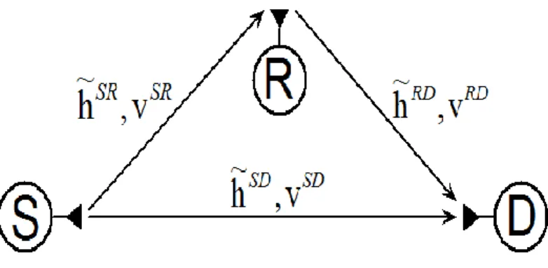
System model is based on [45]. We consider an UWA cooperative wireless communication scenario where the source node S transmits to the destination node D with the assistance of relay node R each of which is equipped with a single pair of transmit and receive antenna. The cooperation is based on the receive diversity (RD) protocol [15] with a single-relay amplify-and-forward (AF) relaying with half-duplex nodes. In our work, we assume that the relay node does not perform the channel estimation to keep its complexity as low as possible. As shown in Figure 3.1, in the broadcasting phase, the source node transmits to the destination and the relay nodes. In the relaying phase, the relay node forwards a scaled noisy version of the signals received from the source. The channel between each node pair is assumed to be
16
quasi-static frequency-selective Rician fading. The channel impulse responses (CIRs) for
, and
Links are sparse and denoted by , and having maximum discrete-valued multipath delays , and , respectively. , and
denote the number of non-zero elements of the multipath channels. Channel coefficients (taps) on each link is a complex Gaussian random variable with independent real and imaginary parts with mean and the variance . Let denotes the power profile of the relevant Rician multipath channel and
. Moreover, Rician қ-factor for th tap is the ratio of the power in the mean component to the power in the diffuse component, i.e. . Therefore, each channel tap is given by
Where is a complex Gaussian random variable with zero mean and unit variance.
The additive ambient noise, generated by underwater acoustic channels has several distinct physical origins each corresponding to particular frequency range [44]. In this thesis, we assume that power spectral density of the ambient noise is modeled in 10 – 100 KHz band as a function of frequency in Hz as
where is the noise variance, and is chosen as a model parameter of the colored noise autocorrelation function Note that the autocorrelation function of the ambient noise can be obtained from (10) as
where is sampling period. Consequently, the complex-valued additive Gaussian ambient noises on
17
and respectively. We assume that CIRs
remain constant over a period of one block transmission and vary independently from block to block.
Figure 3.1: Single-relay transmission model
We now consider an OFDM based UWA relay system with N subcarriers. To avoid inter-symbol interference (ISI) a cyclic prefix is added between adjacent OFDM blocks as shown in Figure 2.1. After FFT and removing the cyclic prefix, time domain received data block in the broadcasting phase (1st time slot) at the relay and the destination nodes are given as
respectively, where is the time-domain signal sample transmitted from the S node at nth discrete time and is the data symbol transmitted over the kth subchannel. In the relaying phase (2nd time slot), the time domain received signal at the destination node is
18
where is the normalization factor. To ensure that the power budget is not violated, the relay node normalizes the receive signal by . Inserting (12) into (14), the vector form of (14) can be expressed as
where is the time-domain received vector on the destination node in the relaying phase, , with being the FFT matrix whose kth row and nth column entry and is a diagonal matrix having the data symbols
on its main diagonal. and
denote the cascaded sparse multipath channel and additive noise on link, respectively, where is the N-sample circular convolution operator and represents a diagonal matrix whose main diagonal vector is .
it obvious from (16) that the ambient noise is non-Gaussian and colored. Thus, without going further toward the channel estimation step, the observation model in (15) can be reduced to the one with additive White non-Gaussian noise by the use of a noise-whitening filter, based on the singular value decomposition (SVD) of the covariance matrix of , , where is an N×N complex valued unitary transformation matrix, is an N×N diagonal matrix with positive real entries and denotes the conjugate transpose operatör. Consequently, the colored noise can be transformed into a White noise through the linear transformation , where is a non-Gaussian white noise vector with identity covariance matrix and is termed as whitening matrix. Multiplying (15) by from the left we obtain the following observation model
19
where and is the convolution matrix generated from data symbols.
In this work, we are mainly interested in estimation of in (17) where is a complex valued, sparse multipath channel vector with non-zero entries, (L<< N), and the associated random channel tap positions, . The received signal in (17) can be rewritten as
where, is the th column vector of the matrix A corresponding to the th multipath channel tap position. Note that the matrix A is known by the receiver completely since it contains only pilot symbols during the training phase in a given frame as shown in Figure 3.2. We model the white,
Figure 3.2: Pilot Scheme of the UWA-OFDM system
non-Gaussian noise samples in (17) as an identically independent distributed (i.d.d.), M-term in Gaussian mixture as follows
20
where , is the nth random mixture index
that identifies which term in Gaussian mixture pdf in (19) produced the additive noise sample and is the probability that is chosen from the mth term in the mixture pdf, with . In (19), denotes the variance of the mth Gaussian mixture.
3.3 Channel Estimation between Source and Destination
In this section we describe the channel estimation. We utilize Eq. (13). Since underwater channels are sparse and additive noise entering the system is colored Gaussian noise, it is very difficult to estimate the underwater channels. OFDM-based channel estimation problem is achieved by using MP algorithm.
(13) can be written in matrix form as
where is the main diagonal of the matrix. The element of the vector is values of the channel frequency response on the subcarrier frequencies. Therefore is
. We can be written as . In this equation inserting (20), the receive signal model is
For the pilot-assisted channel estimation, observation model in (20) corresponding to pilot places, can be written from the model (21) as:
where is produced of F matrix in the pilot lines corresponding to points of interest in a sub-matrix of size . is pilot number. On the other hand is defined as . is covariance matrix of the additive complex Gaussian vector with a zero-mean. matrix is a diagonal matrix having a main diagonal pilot symbols.
21
Sparse structure of the long delay spread channels should be considered in underwater channel estimation. In this part of the study, MP [32] algorithm uses sparse channel estimation, how it applies to underwater acoustic channels are investigated.
We consider observation model from (17) to explain the MP algorithm. In the basic from of the MP algorithm, we first find the column in the matrix , which is best aligned with the signal vector and this is denoted . Then the projection of along this direction is removed from and the residual is obtained. Now the column in A, , which is best aligned with is found and a new residual, is formed. The algorithm proceeds by sequentially choosing the column which best matches the residual until some termination criterion is met. The i. iteration is described in the following paragraph.
We denote the projection onto a vector as
. The vector from most closely aligned with the residual is chosen, where the alignment is measured as the 2-norm (denoted by ) of the projection of the residual onto the vector.
In this case i. dominant factor in the multi-path channel coefficient
is estimated. The new residual vector is then computed as
The iteration is repeated until a specified number of taps, have been selected or the residual becomes sufficiently small.
22
3.4 Channel Estimation between Source, Relay and Destination
We now propose a new iterative algorithm, called the MP-SAGE algorithm, based on the SAGE and the MP techniques for channel estimation employing the signal model given by (17). The SAGE algorithm, proposed by Fessler et al. [46], is a twofold generalization of the so-called “expectation maximization” (EM) algorithm that provides updated estimates for an unknown parameter set . First, rather than updating all parameters simultaneously at iteration (i), only a subset of indexed by is updated while keeping the parameters in the complement set fixed; and second, the concept of the complete data is extended to that of the so-called admissible hidden data to which the observed signal is related by means of a possibly nondeterministic mapping. The convergence rate of the SAGE algorithm is usually higher than that of the EM algorithm, because the conditional Fisher information matrix of given for each set of parameters is likely smaller than that of the complete data given for the entire space. At the ith iteration, the expectation-step (E-step) of the SAGE algorithm is defined
.
In the maximization step (M-step), only is updated, i.e.,
The MP algorithm is an iterative procedure which can sequentially identify the dominant channel taps and estimate the associated tap coefficients by choosing the column of A in (17) which best aligned with the residual vector until all the taps are identified. The detail description of the MP algorithm is given in Sec. 3-C. Finally our proposed MP-SAGE algorithm implements the MP algorithm at each SAGE iteration step by updating, all the dominant channel taps and the associated tap coefficients sequentially. The details of MP-SAGE algorithm is presented below:
23
where , and .
The first step in deriving the MP-SAGE algorithm for estimating based on the received vector y is the specifications of “complete data” and “admissible hidden data” sets whose pdfs are characterized by the common parameters set . To obtain a receiver architecture that iterates between soft-data and channel estimation in the MP-SAGE algorithm, we decompose
into L+1 subsets, representing the parameters, , and , as follows.
The first L subsets of are chosen as , . For each
subset we define , and , where \
denotes the exclusion operator.
The (L+1)st subset of is chosen as by and
At the SAGE iteration (i), only the parameters in one set are updated, whereas the other parameters are kept fixed, and this process is repeated until all parameters are updated. According to the above parameter subset definitions, each iteration of the SAGE algorithm for our problem has two steps:
1) is updated with the MP-SAGE algorithm while is fixed. 2) is updated with the SAGE algorithm while is fixed.
We now derive the MP-SAGE algorithm below by also specifying the corresponding admissible hidden data and complete data sets.
24 3.4.1 Estimation of ,
A suitable approach for applying the MP-SAGE algorithm for estimation of is to decompose the nth sample of the receive signal in (10) into the sum
where
and (28)
and denotes nth element of the . We define the admissible hidden data as
, where and .
To perform the E-Step of the MP-SAGE algorithm, the conditional expectation is taken over given the observation y and given that equals its estimate calculated at ith iteration:
where
25 Inserting (30) in (29) we obtain
where and denote the real part and the conjugate operators, respectively, and is defined as
Recalling (27) it follows that
26
Keeping in mind , the posterior probability density function of the random mixture index at ith iteration, , is evaluated as follows
The vector form of (31) can be written as follows
where from (32) and is
a diagonal matrix with entries that are calculated from (33).
In the M-step of the MP-SAGE algorithm, the estimates of are updated at the ( )st iteration according to
27
where is given by (35). So, taking the derivative of with respect to and equating to zero, we find the final SAGE estimates of at (i+1)st iteration as follows:
Based on the above result, can be sequentially estimated for , incorporating the previous estimates in the MP-SAGE mode as follows:
Step 1) For i=0, determine the initial estimates , , from MP algorithm as described in Sec. 3.4.3.
Step 2) For i (i + 1), and , compute from (31), replacing
with residual vector of the MP algorithm. It can be shown that, the residual vector can be computed recursively as
where and , for all .
Step 3) If go to the next SAGE iteration step.
28
3.4.2 Estimation of
We define the complete data as to estimate the mixture parameters . Now, let us derive the MP-SAGE algorithm.
To perform the E-Step of the MP-SAGE algorithm, the conditional expectation is taken over given the observation y and given that equals its estimate calculated at ith iteration:
where
Inserting (34) in (33) we obtain
where (m) is given in (34).
In the M-step of the SAGE algorithm, the estimates are updated at the ( )st iteration according to the following constraint maximization problem:
29 subject to :
The optimization problem in (42) can be decoupled into two minimization problems. The first one is a convex minimization problem with a constraint and the other is a simple minimization problem without constraint. These problems are given as
1)
subject to :
2)
Solving the first problem in (43) using a convex optimization technique with lagrangian we have
where is given in (34). Keeping in mind (45), it is straight-forward to show that the solution of the minimization problem in (44) is
30
where is a diagonal matrix with entries .
Note that, as seen from (37), the positions of the dominant channel taps are identified and the associated channel tap coefficients are estimated sequentially during the estimation of , , of the SAGE algorithm within the MP framework. More clearly, at (i + 1)st step of the SAGE algorithm, the columns of A.
3.4.3 Initialization of the Algorithm
1) Initialization of . We apply the matching pursuit
(MP) algorithm to determine considering the observation model in (17). As a first step in the MP algorithm, the column in the matrix which is best aligned with the residue vector is found and denoted . Then the projection of along this direction is removed from and the residual is obtained. The algorithm proceeds by sequentially choosing the column which is the best matches until termination criterion is met. At the th iteration, the index of the vector from A most closely aligned with the residual vector is obtained as follows
and the channel tap at position is
31
2) Initializations of the Gaussian-mixture parameters . The empirical pdf of the Gaussian mixture noise in (19) is obtained first by means of the samples generated from the Gaussian distribution of the random vectors , representing the additive Gaussian noise and the channel impulse response on the links , having known covariance matrices. The Gaussian-mixture parameters are then determined by solving the following constrained optimization problem numerically.
with constraints and where is the number of noise samples.
32
Chapter 4
Simulation Results
4.1 Performance of Channel Estimation between Source and Destination
In this section, we present computer simulation results to examine the performance of OFDM-based cooperative communication systems in UWA channels with the target channel estimation algorithm. System parameters for computer simulations are listed as in Table 4.1.
.
Table 4.1 Simulation Parameters for S-D channel estimation algorithm
Number of Subcarriers ( ) 256
Active Number of Subcarriers ( ) 232
Channel Bandwidth ( ) 3KHz Sampling Frequency ( ) Multipath Delays ( ) [0 21 34 52] Ts Multipath Powers ( Ω ) [0.25 0.5 0.15 0.1] Rician Factor (K) 2 dB 0.05 Pilot range (Δ) 4
Figure 4.1 and 4.2 show MSE and SER performance curves of he MP algorithms for binary phase shift-keying (BPSK), quadrature phase shift-keying (QPSK) signaling format. As seen
33
from these curves, the MP algorithm, having excellent channel estimation performance and the symbol error rate outperforms the MP estimators.
Figure 4.1: MP channel estimation for MSE performance
Figure 4.2: Under the channel estimation with the assumption that the channel is known perfectly SER performance comparison
34
4.2 Performance of Channel Estimation between Source, Relay and Destination
In this part, we present computer simulation results to examine the performance of OFDM-based cooperative communication systems in UWA channels with the target channel estimation algorithm. System parameters for computer simulations are listed as in Table 4.2.
Table 4.2 Simulation Parameters for cascaded channel estimation algorithm Number of Subcarriers ( N ) 256 Channel Bandwidth ( BW ) 3 KHz Sampling Frequency ( ) BW Sampling Frequency ( ) 12 KHz Multipath Delays ( ) [0 21 34 52] Ts Multipath Powers ( ) [0.25 0.5 0.15 0.1] Rician Factor ( ) 3dB f0Ts 0.01
Number of Gaussian Mixtures ( M ) 5 Number of OFDM Frame Length ( ) 2 Number of iterations ( imax ) 5
The first estimates of the multipath channel positions and taps utilize in MP-SAGE algorithm are applied by the decreased complexity MP algorithm. The first estimates of the multipath channel positions is applied in the BLUE estimator as well.
35
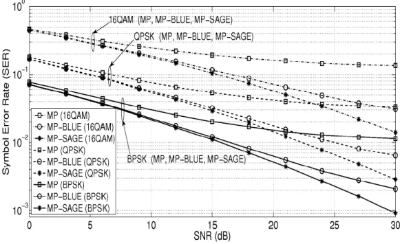
Figure 4.3: SER performance comparisons of the MP-SAGE and MP-BLUE algorithms Figure 4.3 shows SER performance curves of MP, BLUE and MP-SAGE algorithms for binary phase shift-keying (BPSK), quadrature phase shift keying (QPSK) and 16-ary quadrature amplitude modulation (16QAM) signaling format. As seen from these curves, the MP-SAGE algorithm, having excellent channel estimation performance and the symbol error rate outperforms the MP and BLUE estimators. We conclude from these curves that our MP-SAGE algorithm exhibits a superior performance in the estimation of channel tap positions, tap coefficients as well as the additive the Gaussian mixture parameters that models the pdf of the correlative non-Gaussian ambient noise. Particularly, as seen from Figure 4.3 that our estimation algorithm has approximately 3 dB performance gain over the BLUE estimator at SER= when QPSK signaling is employed.
36
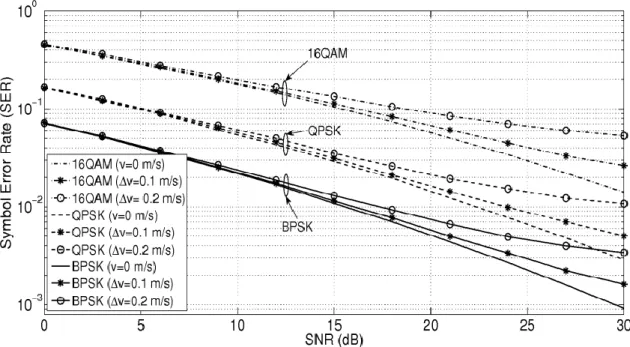
Figure 4.4: SER performance of the MP-SAGE algorithm under the effects of Doppler mismatch
Figure 4.4 exhibits the robustness of the MP-SAGE algorithm to Doppler mismatch as well as the superiority to the MP-BLUE algorithm even under the effects of Doppler mismatch. In these figures, the performance of the proposed algorithm is examined under a Doppler mismatch with the multipath Doppler velocities are generated from a Thikhonov distribution having the support set . Figure 4.4 shows that the proposed MP-SAGE algorithm is quite robust to the changes of Doppler velocity for BPSK, QPSK and 16QAM modulation types for velocities up to 0.2 meter/sec.
37
Chapter 5
Conclusions
In this thesis, we investigated channel estimation problem for cooperative underwater acoustic communication. The thesis consists two parts. In these parts, the transmission from source to the target recipient is realized by means of a relay system. In the first part, source to destination transmission with relay based OFDM system is considered and underwater channel estimation problem is investigated. Underwater channels have a sparse model and the additive noise entering the system is colored Gaussian noise. This makes the underwater channels estimation problem difficult. Due to sparse channel for estimation, we applied the MP algorithm as well as the colored Gaussian noise whitening. In computer simulation, we observed that using MP algorithm having excellent channel MSE and SER estimation performance. In the second study, we have studied a novel channel estimation algorithm for AF cooperative relay based OFDM systems in the presence of sparse underwater acoustic channels and of the correlative non-Gaussian noise modeled with a finite Gaussian mixture pdf. The proposed algorithm was combined with the SAGE algorithm in such a way that each SAGE iteration step, the nonzero taps and the locations of the sparse channel taps were determined and associated channel taps estimated by the MP algorithm. Finally, the computer simulations have shown that UWA channel is estimated very effectively and the proposed algorithm has excellent symbol error rate and channel estimation performance, and is robust to the effects of Doppler mismatch.
38
References
[1] L. Lanbo, Z. Shengli, and C. Jun-Hong, “Prospects and problems of wireless communication for underwater sensor networks,” Wireless Communications and Mobile Computing, vol. 8, no. 8, pp. 977-994, 2008.
[2] M. Stojanovic, “Underwater acoustic communications: Design considerations on the physical layer,” IEEE/IFIP Fifth Annual Conference on Wireless On demand Network Systems and Services (WONS 2008), Garmisch-Partenkirchen, Germany, January 2008.
[3] X. Lurton, Underwater acoustics: an introduction. Springer, 2002.
[4] A. Quazi and W. Konrad, “Underwater acoustic communications,” Communications Magazine, IEEE, vol. 20, no. 2, pp. 24-30, 1982.
[5] M. Stojanovic, “Recent advances in high-speed underwater acoustic communications,” Oceanic Engineering, IEEE Journal of, vol. 21, no 2, pp. 125-136, 1996.
[6] M. Suzuki, T. Sasaki, and T. Tsuchiya, “Digital acoustic image transmission system for deep-sea research submersible,” in OCEANS’92.’Mastering the Oceans Through Technology’. Proceedings., vol. 2, pp. 567-570, IEEE, 1992.
[7] G. Ayela and J. Coudeville, “Tiva: A long range, high baud rate image/data acoustic transmission system for underwater applications,” in Proc. Underwater Defence Technol. Conf, p. 1991, 1991.
39
[8] M. Stojanovic, J. Catipovic, and J. Proakis, “Phase-coherent digital communications for underwater acoustic channels,” Oceanic Engineering, IEEE Journal of, vol. 19, no. 1, pp. 100-111, 1994.
[9] C. Carbonelli and U. Mitra, “A simple sparse channel estimator for underwater acoustic channels,” in OCEANS 2007, pp. 1-6, IEEE, 2007.
[10] W. Li and J. Preisig, “Estimation of rapidly time-varying sparse channels,” Oceanic Engineering, IEEE Journal of, vol.32, no. 4, pp. 927-939, 2007.
[11] A. Morozov and J. Preisig, “ Underwater acoustic communications with multi-carrier modulation,” in OCEANS 2006, pp. 1-6, IEEE, 2006.
[12] B. Li, J. Huang, S. Zhou, K. Ball, M. Stojanovic, L. Freitag, and P. Willett,” MIMO-OFDM for high-rate underwater acoustic communications,” Oceanic Engineering, IEEE Journal of, vol. 34, no. 4, pp. 634-644, 2009.
[13] E. Van Der Meulen, “Three-terminal communication channels,” Advances in applied Probability, pp. 120-154, 1971.
[14] T. Cover and A. Gamal, “Capacity theorems for the relay channel,” Information Theory, IEEE Transactions on, vol. 25, no. 5, pp. 572-584, 1979.
[15] J. Laneman, D. Tse, and G. Wornell, “Cooperative diversity in wireless networks: Efficient protocols and outage behavior,” Information Theory, IEEE Transactions on, vol. 50, no. 12, pp. 3062-3080, 2004.
[16] J. Laneman and G. Wornell, “Distributed space-time-coded protocols for exploiting cooperative diversity in wireless networks,” Information Theory, IEEE Transactions on, vol.49, no. 10, pp.2415-2425, 2003.
[17] R. Nabar, H. Bolcskei, and F. Kneubuhler, “Fading relay channels: Performance limits and space-time signal design,” Selected Areas in Communications, IEEE Journal on, vol. 22, no. 6, pp. 1099-1109, 2004.
40
[18] H. Ochiai, P. Mitran, and V. Tarokh, “Variable-rate two-phase collaborative communication protocols for wireless networks,” Information Theory, IEEE Transactions on, vol. 52, no. 9, pp. 4299-4313, 2006.
[19] M. Uysal and M. Fareed, “Cooperative diversity systems for wireless communication,” INFORMATION AND CODING THEORY, 2008.
[20] F. Onat, Y. Fan, H. Yanikomeroglu, and H. Poor, “Threshold-based relay selection for detect-and-forward relaying in cooperative wireless networks,” EURASIP Journal on Wireless Communications and Networking, vol. 2010, p. 43, 2010.
[21] K. Hwang, Y. Ko, and M. Alouini, “Performance analysis of two-way amplify and forward relaying with adaptive modulation,” in Personal, Indoor and Mobile Radio Communications, 2009 IEEE 20th International Symposium on, pp. 2340-2344, IEEE, 2009.
[22] B. Rankov and A. Wittneben, “Spectral efficient signaling for half-duplex relay channels,” in Signals, Systems and Computers, 2005. Conference Record of the Thirty-Ninth Asilomar Conference on, pp. 1066-1071, IEEE, 2005.
[23] Y. Han, S. Ting, C. Ho, and W. Chin, “High rate two-way amplify-and-forward half-duplex relaying with ostbc,” in Vehıcular Technology Conference, 2008. VTC Spring 2008. IEEE, pp. 2426-2430, IEEE, 2008.
[24] Z. Han, Y. Sun, and H. Shi, “Cooperative transmission for underwater acoustic communications,” in Communications, 2008. ICC’08. IEEE International Conference on, pp. 2028-2032, IEEE, 2008.
[25] H. Yang, F. Ren, C. Lin, and B. Liu, “Energy efficient cooperation in underwater sensor networks,”in Quality of Service (IWQoS), 2010 18th
International Workshop on, pp. 1-9, IEEE, 2010.
41
[26] S. Al-Dharrab and M. Uysal, “Cooperative Diversity in the Presence of impulsive Noise,” IEEE Trans. Wireless Commun., vol. 8, no. 9, pp. 4730-4739, Sept. 2009.
[27] K. Tu, T. M. Duman, J. G. Proakis, M. Stojanovic, “Cooperative MIMO-OFDM communications: Receiver design for Doppler-distorted underwater acoustic channels,” in Asilomar 2010, Pacific Grove, CA, USA, Nov. 7-10 2010.
[28] C. S. Patel and G. Stuber, “Channel estimation for amplify and forward relay based cooperative diversity systems,” IEEE Trans. Wireless Commun., vol. 6, no. 6, pp. 374-377, June 2007.
[29] W. Li, J. C. Preisig, “Estimation of rapidly time-varying sparse channels,”32, vol. 32, no. 4 , pp. 927-939, Oct. 2007.
[30] C. R. Berger, S. Zhou, J: Preisig, and P. Willet, “Sparse Channel Estimation for Multicarrier Underwater Acoustic Communication: From Subspace Methods to Compressed Sensing,” IEEE Trans. Signal Process., vol. 58, no. 3, pp. 1708-1721, 2010.
[31] C. Qi, X. Wang, L. Wu, “ Underwater acoustic channel estimation based on sparse recovery algorithms,” IET Signal Process., vol. 5, no. 8, pp . 739-747, Dec 2010.
[32] S. F. Cotter and B. D. Rao, “Sparse channel estimation via matching pursuit with application to equalization,” IEEE Trans. Commun., vol. 50, no. 3, pp. 374-377, March. 2002.
[33] E. Panayirci, H. Senol and H. V. Poor, ”Joint channel estimation, equalization and data detection for OFDM systems in the presence of very high mobility,” IEEE Trans. Signal Process., vol. 58, no. 8, pp. 4225-4238, Aug. 2010.
[34] M. Stojanovic and J. Preisig, “Underwater acoustic communication channels: Propagation models and statistical characterization,” Communications Magazine, IEEE, vol. 47, no. 1, pp. 84-89, 2009.


![Table 4.2 Simulation Parameters for cascaded channel estimation algorithm Number of Subcarriers ( N ) 256 Channel Bandwidth ( BW ) 3 KHz Sampling Frequency ( ) BW Sampling Frequency ( ) 12 KHz Multipath Delays ( ) [0 21 34 52] T](https://thumb-eu.123doks.com/thumbv2/9libnet/4336725.71636/49.892.206.688.329.682/simulation-parameters-estimation-subcarriers-bandwidth-frequency-frequency-multipath.webp)