Magnetic resonance imaging (MRI) guidance for coronary in-terventions offers potential advantages over conventional x-ray angiography. Advantages include the use of nonionizing radiation, combined assessment of anatomy and function, and three-dimensional assessment of the coronary arteries leading to the myocardium. These advantages have prompted a series of recent studies in this field. Real-time coronary MR angiography, with low-dose catheter-directed intraarterial (IA) infusion of contrast media, has achieved in-plane spatial resolution as low as 0.8⫻ 0.8 mm2
and temporal resolution as short as 130 msec per image. Catheter-based IA injection of contrast agent has proven useful in the collection of mul-tislice and three-dimensional images, not only for coronary intervention guidance, but also in the assessment of regional myocardial perfusion fed by the affected vessel. Actively visi-ble guidewires and guiding catheters, based on the loopless antenna concept, have been effectively used to negotiate tor-tuous coronary vessels during catheterization, permitting placement of coronary angioplasty balloon catheters. Passive tracking approaches have been used to image contrast agent– filled coronary catheters and to place susceptibility-based endovascular stents. Although the field is in its infancy, these early results demonstrate the feasibility for performing MRI-guided coronary interventions. Although further methodolog-ical and technmethodolog-ical developments are required before these methods become clinically applicable, we anticipate that MRI someday will be included in the armamentarium of tech-niques used to diagnose and treat coronary artery disease.
Key Words: coronary artery; interventional MRI; coronary
MR angiography; real-time imaging
J. Magn. Reson. Imaging 2004;19:734 –749. © 2004 Wiley-Liss, Inc.
RECENT ADVANCES IN MR methodology and instru-mentation have allowed the rigorous exploitation of the
new field of “interventional MRI,” i.e., the methodology of performing diagnostic and, primarily, therapeutic in-terventions under MRI guidance (1–3). Despite general-ized acceptance of magnetic resonance angiography (MRA) as a diagnostic tool, performing therapeutic in-terventions under MRI guidance has not yet been trans-lated successfully into the clinical realm. X-ray angiog-raphy is the current reference standard for guiding coronary artery intervention such as balloon angio-plasty or stent placement. Coronary angiography per-formed under x-ray guidance provides outstanding submillimeter spatial and subsecond temporal resolu-tion for guiding vascular intervenresolu-tions (4).
Despite the indisputable role of x-ray fluoroscopy, MRI guidance for endovascular procedures offers sev-eral important potential advantages over conventional x-ray guidance: 1) Because of its intrinsic sensitivity to flow and soft-tissue contrast, MRI allows the combined assessment of vessel morphology and morphology and function of myocardial tissue. This provides the ability to detect changes in cardiac function following coronary interventions; 2) MRI permits the selection of three-dimensional volumes and arbitrary scan-planes, which might depict the desired anatomy for the procedure, without the need to manually reposition the patient or the imaging instrument; 3) MRI avoids ionizing radia-tion exposure to the patient and the medical team per-forming the procedures; and 4) MRI does not use iodin-ated contrast agents, thereby avoiding the risk of nephrotoxicity and allergic reactions.
MRI-guided vascular procedures are still early in their development. Most studies have been performed in animals, with little published experience in human beings. In animal models, published applications of MRI-guided endovascular interventions include inferior vena cava filter placement (5,6), percutaneous translu-minal angioplasty (PTA) of the aorta (7–9) and renal arteries (10,11), stent placement within the iliac artery (12,13) and aorta (13,14), coronary angiography (15,16), and carotid artery aneurysm embolization (17). In human subjects, MRI-guided hemodialysis arterio-venous and loop graft fistulography (18) and iliac artery stent placement (19) have also been performed. Serfaty et al (16) first demonstrated the feasibility of coronary MRA using catheter-directed intraarterial (IA) injec-tions of gadolinium (Gd)-based contrast agent.
1Cardiovascular Imaging Laboratory, Mallinckrodt Institute of
Radiol-ogy, Washington University, St. Louis, Missouri.
2Center for Image Guided Interventions, Johns Hopkins University,
Baltimore, Maryland.
3Department of Radiology, Northwestern University, Chicago, Illinois.
Contract grant sponsor: National Institutes of Health: Contract grant numbers: RO1HL067924; K08 DK60020; R01 HL70859.
*Address reprint requests to: N.V.T., Cardiovascular Imaging Labora-tory, Mallinckrodt Institute of Radiology, Washington University Medi-cal Center, 510 S. Kingshighway Blvd., Campus Box 8225, St. Louis, MO 63110. E-mail: [email protected]
Received December 17, 2003; Accepted February 12, 2004. DOI 10.1002/jmri.20071
Published online in Wiley InterScience (www.interscience.wiley.com).
The benefits of MRI might allow it to be used as a comprehensive modality to diagnose and treat coronary artery disease in a single session. This combined ap-proach offers the advantage of allowing the incorpora-tion and integraincorpora-tion of different diagnostic or therapeu-tic procedures within the same session. For example, early assessment of myocardial perfusion of the re-claimed myocardium after a percutaneous translumi-nal coronary angioplasty (PTCA) may identify regions of “no-reflow” (20 –22); contrast-enhanced MRI can be used to assess regional myocardial perfusion (23,24), including transmural perfusion gradients (25). Even more intriguing is the possibility of assessing athero-sclerotic plaque with intracoronary MRI (26 –28) to guide treatment decisions that may address the issue of high rates of restenosis after PTCA (29). The demonstra-tion of MR-guided gene therapy delivery (30) is yet an-other illustration of the potential of MRI in interven-tional cardiology. The above examples are a partial list of the possible diagnostic or therapeutic approaches that can be included in an MR-based comprehensive method of cardiac patient management.
Current MRI-guided coronary interventions that have been demonstrated in animals include real-time an-giography (16,31,32), catheterization (33–35), balloon angioplasty (34), and stent placement (36). In this re-view, we examine approaches towards performing real-time coronary MRA and coronary interventions.
TECHNIQUES AND METHODS OF IMPLEMENTATION
To guide coronary interventions, MR methods must have the following prerequisites: 1) sufficient volume of coverage for the targeted tortuous and branched coro-nary vasculature; 2) high acquisition speed; 3) high vessel-to-tissue contrast; 4) diagnostic quality images with high in-plane spatial resolution; and 5) suitable MR-compatible and visible interventional instrumenta-tion. Satisfying these requirements is challenging, es-pecially when compared with the gold standard of x-ray guidance. However, several MRI techniques (33–36) can be used individually or combined together to address these challenges.
Three major phases can be identified during a coro-nary intervention that dictate the development of spe-cialized MR methodology: 1) anatomical imaging for identification and characterization of the vascular le-sion; 2) guidance and accurate positioning of the inter-ventional instrumentation to the targeted area; and 3) assessment of the pathophysiology of the targeted tis-sue (the latter is pertinent to both the initial screening of the disease and for assessment of the procedure). Thus far, the major focus of MR-guided coronary inter-ventions has been on the development of real-time cor-onary MRA techniques and on the monitoring of MR-compatible vascular interventional devices.
Contrast-Enhanced Coronary MRA with IA Infusion of MR Contrast Agents
Currently, the primary method of achieving real-time coronary MRA is catheter-directed localized IA delivery
of low dose Gd-based MR contrast agent (16,31,37). This contrast delivery is coupled with fast imaging pulse sequences, which are highly T1-weighted and saturate the background tissue’s unwanted signal to generate high coronary signal enhancement. This ap-proach is similar to x-ray angiography, and the ratio-nale for its use is supported by several benefits.
Catheter-directed delivery allows the conservation of contrast agent, thereby facilitating multiple or long-duration injections without exceeding doses used in routine standard of care. Multiple and long-duration injections are important during coronary procedures to define vascular anatomy, confirm intraluminal position of endovascular devices, and to document change in vascular anatomy following an intervention. Conven-tional intravenous (IV) injections use larger amounts of contrast agent, have longer transit periods, and are prone to dispersion. Catheter-directed injections, how-ever, use smaller volumes of dilute contrast agent to generate comparable coronary artery–myocardial con-trast-to-noise ratios (CNR). An additional benefit is that the low dose of Gd results in less background tissue enhancement, while enhancing only the artery of inter-est. Because adjacent vascular beds remain sup-pressed, there is clearer local artery depiction. Cathe-ter-directed IA infusion of Gd-based contrast agents has been investigated using a variety of coronary MRA protocols, such as short-duration (16,37) and long-du-ration (31) real-time imaging of projections (16), single-slab (31,32,37), multiple planes (31), three-dimen-sional volumes (32), and first-pass perfusion (31).
Real-Time Two-Dimensional Coronary MRA with IA Contrast Agent Infusion
When a rapid vascular roadmap is desired (e.g., to mon-itor the advancement of an interventional device), then fast two-dimensional sequences are the methods of choice (16,33–35,37). Standard thin-slice two-dimen-sional sequences suffice when the targeted blood ves-sels are located within a well-defined imaging plane, such as in the peripheral circulation. However, for the tortuous and continuously moving coronary vessels, thick-slab two-dimensional imaging is more appropri-ate. This approach has been adopted either with non– slice-selective (16,33,34) or with 2–20-cm thick-slab imaging (31,35). Most often identified in the literature as “projection MRA,” thick-slab imaging offers certain important features suitable for real-time coronary im-aging. When the projection plane of the non–slice-se-lective version (16) or the orientation of the thick slab (31,37) are appropriately prescribed, the entire portion of a tortuous vessel can be imaged with a single acqui-sition. In addition, the thick slab can be set to include the vessel without electrocardiographic (ECG)-trigger-ing, thereby ensuring the presence of the targeted ves-sel independent of the heart phase. Moreover, these volume approaches are appropriate for imaging the pre-shaped catheters and devices used for coronary cathe-terization.
Since projection (i.e., thick-slab) MRA collects signals from a large volume, the background signal can be overwhelmingly higher than that of a
contrast-en-hanced vessel. Therefore, over a large volume, it is of paramount importance to retain the high contrast-en-hanced blood signal while suppressing the background signal. Since the vessels are contrast-enhanced due to T1 shortening, T1-weighted sequences, which suppress the long T1 species and retain the short T1 species, are the most appropriate. This can be achieved using a conventional steady-state gradient-echo (GRE) se-quence with a large flip angle, as has been previously reported (16), or with magnetization-prepared se-quences (31,32,35).
Figure 1 shows representative results from the first demonstration of real-time coronary MRA with IA in-fused contrast-agent enhancement (16) in dogs. In these studies, a catheter placed in the left coronary artery, under x-ray fluoroscopy, was used to locally deliver Gd-based contrast agent. A fast spoiled GRE sequence (TR/TE/excitation angle ⫽ 4.4 msec/1.4 msec/90°; FOV ⫽ 32 ⫻ 16 cm; matrix ⫽ 256 ⫻ 128; imaging time⫽ 300 msec per image) was used to gen-erate heavy T1-weighted contrast to suppress back-ground signal and enhance the contrast agent–per-fused vessel. As these results show, the use of a 90° non–slice-selective excitation angle generates efficient background signal suppression.
An alternative approach for imaging IA-enhanced coronary vessels is based on heavily T1-weighted mag-netization preparation pulse sequences (31,32,35). Currently, three T1-weighted magnetization-driven steady-state preparation schemes have been used for real-time coronary MRA with IA injection of Gd-based contrast agents. Figure 2 summarizes these pulse se-quences. With these sequences, suppression of rela-tively long T1 species (T1⬎ 150 msec, including fat and myocardium) is achieved with preparation pulses,
Figure 1. Real-time projection MR angiographic images of the left coronary artery of a dog, with successive images obtained at
300 msec each. A–J: Images obtained in the right anterior oblique caudal view show the left anterior descending coronary artery (curved arrow in H) and the circumflex coronary artery (straight arrow in H) at different arterial phases. Images E, G, and I were obtained during systole—note the straight left anterior descending coronary artery—and provide limited depiction of the circumflex coronary artery. Conversely, the circumflex coronary artery is well delineated in F, H, and J, which were obtained during diastole—note the displaced left anterior descending coronary artery. K: Right anterior oblique caudal view of left ventricular myocardial perfusion phase. L: Right anterior oblique caudal venogram of the great cardiac vein (arrowhead). (Reprinted with permission from reference 33.)
Figure 2. Diagrams of the magnetization-prepared pulse
se-quences currently used to generate T1-weighting for real-time coronary MRA. A: The SR sequence implemented for cardiac-triggered multislice acquisitions. The initial non–slice-selec-tive saturation pulse ensures that the magnetization evolution is the same for all slices. Cardiac triggering was used for acquisition of the same slice of the multislice set at the same cardiac phase. The SR sequence was also used for single-plane nontriggered acquisition. B: The IR sequence used for two-dimensional real-time projection imaging. The non–slice-selec-tive inversion is followed by an inversion recovery period (TI) and spoiling gradients, and then by the acquisition of a seg-ment of the k-space (i.e., N lines) with a standard spoiled GRE acquisition scheme. C: The ECG-triggered three-dimensional MR angiographic sequence with 100 non–slice-selective prep-aration pulses (for background suppression) initiated after the R wave. At the end of the preparation pulses, a non–slice-selective inversion pulse is applied, followed by a TI and the acquisition of N phase-encoding lines with a spoiled GRE.
which precede the acquisition. With these sequences, T1-weighting is achieved with non–slice-selective satu-ration pulses before the acquisition of an entire image (Fig. 2A), inversion pulses (Fig. 2B), or the combination of inversion and steady-state magnetization suppres-sion pulse trains (Fig. 2C). Then, acquisition can be performed with much smaller flip angles, so the effects of the slice profile are greatly reduced, while tissue radiofrequency (RF) power deposition remains low. With these sequences, the excitation pulses during im-age acquisition act in accord with the preparation pulses to maintain or augment the vessel-to-tissue con-trast.
Figures 3 and 4 show results of real-time coronary MRA during IA infusion of Gd-based agent using the saturation recovery (SR) and inversion recovery (IR) preparation schemes. With SR and IR, the T1-weighting and background suppression are created with non–sec-tion-selective saturation or inversion pulses. The main difference between SR and IR is that with IR the inver-sion time (TI) can be adjusted to achieve wider nulling of the long T1 species. Since with SR there is no magne-tization nulling point, the evolution delay between the saturation pulse and the acquisition must be kept as short as possible. Although SR is inherently faster than IR, the penalty is less efficient saturation. Both SR and IR magnetization preparation schemes are useful for suppressing background signal and improving CNR be-tween blood and background tissue (32,37,38). When
using IR preparation in each cardiac cycle, only back-ground tissues that have a rather narrow T1 range will be suppressed. Green et al (32) addressed this limita-tion by combining both steady-state and IR preparalimita-tion techniques (Fig. 3) to uniformly suppress background tissues over a wider range of inversion times, while retaining high blood signal as in non–ECG-triggered imaging.
For contrast-enhanced MRA, spoiled GRE sequences have been predominantly used. An alternative ap-proach is true fast imaging with steady-state precession (True-FISP), which generates coronary images with higher CNR and signal-to-noise ratio (SNR) in compar-ison to spoiled GRE (35,39). Using a slab thickness of 5 cm, comparisons (39) demonstrated that the mean cor-onary artery SNR for True-FISP was 10.0⫾ 1.2 and for conventional GRE imaging it was 5.2⫾ 0.8. Mean cor-onary artery CNR with True-FISP was 7.1⫾ 0.7, while with conventional GRE imaging sequence it was 3.5⫾ 0.7. These represent SNR and CNR increases of approx-imately a factor of two using the True-FISP sequence (P⬍ 0.05).
Optimization of IA Contrast Agent Injections
Gd-based MR contrast agents shorten both the longi-tudinal relaxation time (T1) and the apparent trans-verse relaxation time (T2*). While shortening of T1 re-sults in the desired MR signal enhancement, the
Figure 3. A sample of frames from a two-dimensional non–ECG-triggered real-time MR acquisition depicts the progression of
contrast agent through the LCx after IA injection of 3 mL of 9% (45 mM) diluted contrast agent. The temporal resolution was three frames per second. A: Before contrast agent enters the LCx, all signal in the field of view is suppressed. B: Contrast agent was injected into the LCx (arrow) through the catheter, which is located in the proximal portion of the artery. C: The LCx enhances, resulting in a coronary MR angiogram. A circumflex marginal artery (arrowhead) is visible in the distal portion of the LCx. D: Contrast agent perfuses into the myocardium (arrows) and begins washing out of the myocardium (E). (Reprinted with permission from reference 32.)
concomitant reduction of T2* results in signal loss with techniques such as GRE and echo planar imaging (EPI) pulse sequences, which are fast, but are also T2*-sen-sitive. The competing T1 and T2* shortening mecha-nisms result in an optimal range of Gd concentrations, which maximizes the blood signal. Determination of the optimal concentration of dilute Gd for IA MRA has been addressed theoretically (40,41) and experimentally, on static (16,42) and dynamic (43) phantoms, and in vivo (16,40,43,44). The key points of these studies are that: 1) satisfactory vascular depiction occurs over a rela-tively broad range of arterial Gd concentrations with little practical difference in vessel enhancement, or SNR between 6% (30 mM) and 9% (45 mM) (16,40,44); and 2) optimal arterial Gd concentration depends on the spe-cific imaging parameters.
Figure 5, which shows initial studies by Serfaty et al (16) for the calibration of the optimal dose for use with a 90° excitation-pulse sequence, clearly depicts that high SNR can be achieved over a broad range of Gd concentrations. It clearly shows the wide range of mal Gd-based contrast agent concentrations for opti-mal contrast with the 90° excitation-angle projection
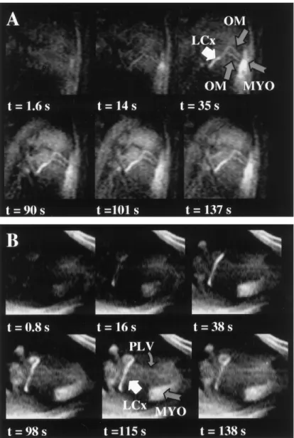
Figure 4. Example of an angiographic multislice
study with the SR-prepared GRE that collected 180 frames composed of five slices prescribed to image multiple coronary vessels over a period of 2.3 min-utes, during intraarterial infusion of Gd-based con-trast agent. A,B: Show selected six-frame sets of two of the slices. The coronary arteries are clearly visu-alized for over two minutes. Note that the agent-perfused myocardium (MYO) shows sustained con-trast enhancement secondary to the accumulation of the agent, yet does not affect the visualization of the proximal portions of the LAD, LCx, and OM. (LAD⫽ left anterior descending, LCx⫽ left circumflex, OM ⫽ oblique marginals; PLV⫽ posterior left ventricular, MYO ⫽ agent-perfused myocardium). (Reprinted with permission from reference 31.)
Figure 5. Graph shows signal intensity measured in vitro as a
function of gadopentetate dimeglumine (Gd-DTPA) concentra-tion, plotted on an inverse logarithmic scale. With use of a fast spoiled-GRE sequence (4.4 msec/1.4 msec; flip angle⫽ 90°), maximal signal intensity is attained for a Gd-DTPA concentra-tion between 15.60 and 62.50 mmol/L (mM). (Reprinted with permission from reference 33.)
MRA. Comparison of the left circumflex (LCx) coronary artery SNR for the different injection schemes, shown in Fig. 6, demonstrates statistically significant differences in mean SNR between each of the three injection rates: 0.5 mL/second, 1.0 mL/second, and 1.5 mL/second;
P⬍ 0.05). The mean SNRs using the 6% and 9% diluted
contrast agent were significantly greater than that with 3% (15 mM) diluted contrast agent (P ⬍ 0.05). There was no statistical difference in mean SNR between 6% and 9% diluted contrast agent (P ⬎ 0.05). Figure 7 illustrates the vessel SNR and the vessel-to-tissue CNR of the LCx at five consecutive angiographic sessions performed with IA infusion of Gd-based contrast agent on three dogs using the SR-prepared GRE sequence. In each session, 1.5 mmol Gd was infused and the ses-sions were separated by two to three minutes. The SNR (P ⫽ 0.60) and CNR (P ⫽ 0.94) remained essentially unchanged over all five consecutive angiographic ses-sions, demonstrating that multiple low-dose, slow infu-sions of Gd-based MR contrast agent can be performed without compromise of the vessel CNR. This is a critical point, since vascular interventions require that multi-ple consecutive coronary injections be performed with-out compromising vessel CNR.
Conventional extracellular MR Gd chelates diffuse and accumulate to the extravascular space, thereby reducing the vessel-to-tissue contrast. In principle, with IA contrast agent delivery, the vessel contrast can be maintained if the low-dose agent delivery is slow enough to allow for sufficient tissue contrast-agent clearance (16,31,32,37). Moreover, if the localized con-trast-agent delivery is appropriately adjusted, then IA enhancement can be maintained for long durations (⬇2.5 minutes) and multiple consecutive infusions (31). The panel of images in Fig. 8A demonstrates that the contrast-enhanced LCx is consistently and clearly seen over a period of 2.3 minutes. To better appreciate and
quantify the contrast enhancement of the coronary ves-sels, signal intensity (SI) time curves were generated from these angiographic studies (Fig. 8B). The SI time curves were extracted from ROIs prescribed to include the enhanced coronary vessel (ROI-1), myocardium (ROI-2), and chest wall (45). The vessel-containing ROI-1 was made large enough to include the coronary artery at all time frames, to account for the motion of the heart. The vessel SI (SIVESSEL) was then calculated
by removing the estimated contribution of tissue to the SI of ROI-1. Based on the assumption that the relative vessel and tissue contributions in ROI-1 are the same in every frame of the time series, the vessel SI was calculated by subtracting a tissue contribution equal to the area-normalized SI of the adjunct tissue ROI-2, weighted with the relative area of the tissue in the ROI-1. The vessel weighted time curve for LCx, with the tissue contribution removed (based on the SI of ROI-2), shows a fast contrast enhancement following the ini-tialization of the Gd infusion that remains fairly con-stant (0.94⫾ 0.14 arbitrary units [au]) over the period of agent delivery, (spanning about 2.3 minutes; hori-zontal gray bar), and then recovers after discontinua-tion. In contrast, the myocardial ROI-2 shows delayed onset and progressively increased enhancement, since it receives and accumulates Gd at later frames after circulation. The chest fat demonstrates virtually no sig-nal changes.
Figure 6. Bar graph shows SNR vs. contrast agent
concentra-tion and injecconcentra-tion rate after IA injecconcentra-tion of diluted contrast agent. Changing the injection rate or increasing the concen-tration more than 6% (30 mM) did not yield statistically sig-nificant improvements in SNR. [Gd]⫽ gadolinium chelate con-centration, a.u.⫽ arbitrary units. (Reprinted with permission from reference 32.)
Figure 7. The SNR of the LCx (A) and the CNR of the LCx (B)
vs. the myocardium, at five consecutive angiographic sessions for three dogs. The CNR of the LCx was calculated relative to a myocardial ROI placed at the vicinity of the vessel. In each session, 1.5 mmol Gd-based contrast agent was infused, with a constant rate of 0.0125 mmol/second. The vessel SNR and CNR show little change over the five consecutive angiographic sessions.
Multislice and Three-Dimensional Coronary MRA With IA Infusion of Gd-based Contrast Agents
MRI offers the capability, unmatched by any other mo-dality, to image three-dimensional volumes or two-di-mensional projections in any arbitrary orientation. This capability may provide better visualization of tortuous and branched vasculature and facilitate guidance of complex interventions. Both approaches have been successfully employed with IA infusion of Gd-based contrast agent in the coronary artery. In contrast, with x-ray angiography, changing the orientation of the im-age projection plane requires repositioning of the x-ray device and additional contrast agent injections.
When assessment of multiple views or simple volu-metric reconstruction is desired, then oblique orienta-tion multislice approaches can be more time efficient. Dynamic coronary MRA of different projections of the same vessel or multiple vessels has been shown by repetitively collecting multislice frames (31). Figure 9 shows a representative example from a study where different slices of a multislice frame were prescribed in oblique orientations, to depict the LCx, the left anterior descending (LAD), and obtuse marginals (OM). Using an SR-prepared GRE sequence with cardiac gating, each slice of a multislice frame was collected at the same cardiac phase.
Three-dimensional sequences are suitable choices when high spatial resolution and multiplanar volu-metric reconstructions are desired. Applications of these sequences may include the detailed mapping of the targeted vascular tree, or the identification and characterization of a stenotic coronary lesion. Three-dimensional contrast enhanced coronary MRA with IA infusion has been demonstrated on dogs (32). Fig-ure 10 shows a scout image (Fig. 10A) and the max-imum intensity projection image (Fig. 10B) from a contrast-enhanced three-dimensional MRA collected
during IA infusion of Gd-based contrast agent. Excel-lent suppression of the background tissue signal throughout the imaging volume was achieved with the combined steady-state and IR magnetization preparation scheme, as shown in Fig. 10B. Contrast enhancement was performed by infusing 12 mL of 6% (30 mM) diluted contrast agent during a 20 second period and achieving a mean SNR in the LCx of 3.90⫾ 0.05 (SD). Although the equivalent of only 0.7 mL of undiluted contrast agent was used for vessel en-hancement, the LCx is clearly depicted, with sharply defined vessel boundary. Moreover, two circumflex marginal arteries are also visible. Figure 11 shows another example of a three-dimensional coronary MRA with IA Gd, comparing a two-dimensional dy-namic coronary MRA (Fig. 11A) spatially-matched with partitions from the contrast-enhanced (Fig. 11B) and nonenhanced (Fig. 11C) three-dimensional coro-nary MRA. In these studies, three-dimensional imag-ing was performed usimag-ing a segmented IR sequence and contrast enhancement with continuous infusion of low concentration Gd (50 mM) with slow rate (0.2 mL/second). With this protocol, the SNR of the LCx was 4.2⫾ 0.1. In these images, a double bifurcation originating from the LCx is clearly seen in the three-dimensional partition and to a lesser extent in the two-dimensional dynamic image (resolution 1.5⫻ 1.5 mm2).
These preliminary studies demonstrate that multi-slice two-dimensional and three-dimensional coro-nary MRA with IA infusion of contrast agent can pro-vide a more detailed assessment of the coronary tree. Moreover, because they require a low dose of Gd-based agent, background contrast during an inter-ventional procedure is not significantly affected. This feature is useful in monitoring coronary interventions when three-dimensional imaging or multislice
proto-Figure 8. A: Representative six-frame panel of images collected with the SR GRE during infusion of Gd-DTPA in the left main,
spanning a period of over two minutes. The contrast-enhanced coronary vessels are clearly and consistently observed over the entire series, even after two minutes of continuous Gd-DTPA infusion. B: Contrast enhancement time curves for the ROI-1 prescribed to include the proximal portion of the LCx in all the time frames. The vessel weighted time curve (solid thick line), with the tissue relative contribution removed (based on the SI of ROI-2), shows a fast contrast enhancement following the initializa-tion of the Gd-DTPA infusion, which remains fairly constant (0.94⫾ 0.14 au) over the period of agent delivery spanning about 2.3 minutes (horizontal gray bar), and then recovers after discontinuation. The myocardial ROI shows delayed onset and progressively increased enhancement, since it receives and accumulates Gd-DTPA at later frames. The chest wall demonstrates virtually no signal enhancement. Data from references 31 and 45.
cols may be interleaved with single-plane real-time two-dimensional imaging.
Myocardial First-Pass Perfusion Assessment with IA Contrast Injection
An important benefit offered by MRI, which is not available for x-ray angiography, is the ability to as-sess changes in end-organ function, such as regional myocardial perfusion (23) and myocardial viability
(46 – 48). These techniques offer alternative methods to characterize the functional significance of coronary artery disease, rather than relying on coronary anat-omy alone. During MR guided coronary interventions, such diagnostic protocols can be performed before, during, and after the intervention to assess the progress of the procedure and to potentially alter the anticipated treatment. Although not yet proven, re-gional myocardial perfusion assessment with
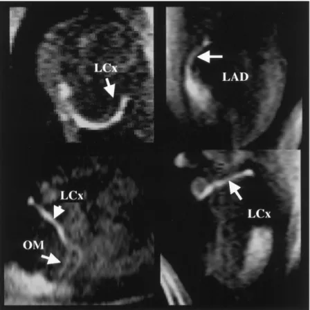
first-Figure 9. Four out of six slices from a
dy-namic coronary MRA (SR preparation; 130 msec per image; 1.4⫻ 2.8 mm2; triggered mul-tislice) during intracoronary infusion of Gd-DTPA in the left main. These multislice frames were selected from a time series of 180 frames (LAD ⫽ left anterior descending, LCx ⫽ left circumflex, OM⫽ obtuse marginals.
Figure 10. A: MR localization (scout) image shows the LCx (arrows) of a dog before injection of contrast agent. B: Maximum
intensity projection image from three-dimensional MR angiography of the LCx of the same dog after IA injection of 12 mL of 6% (30 mM) contrast agent. Contrast agent is injected through the catheter in a retrograde fashion from the proximal portion of the artery (arrow). Two circumflex marginal arteries (arrowheads) are visible. The in-plane resolution of the image was 0.9⫻ 0.8 mm2. The position and orientation of this image are the same as those in A. (Reprinted with permission from reference 32.)
pass Gd-based contrast agent may be improved when IA injections are used, because the local delivery pro-vides a more compact input bolus. Moreover, with low-dose IA contrast agent infusion, first-pass stud-ies can be interleaved with angiographic imaging to assess the progress of the procedure.
Figure 12 shows results from a first-pass study performed with IA injection of Gd into the left main coronary artery (31). The multislice frame in Fig. 12A demonstrates a 270% peak enhancement in the an-terior, anteroseptal, and apical posterior myocar-dium. In contrast, minor enhancement of no more than 25% is observed in the posterolateral and lateral walls; this enhancement appears later since these territories are perfused with Gd at subsequent recir-culation. The above regional perfusion pattern is con-sistent with the dominant left coronary artery system that preferentially feeds the anterior, anteroseptal, and anteroposterior walls of the canine heart. In con-trast, during peripheral injection of Gd via the femo-ral vein (Fig. 12C), all myocardial territories demon-strate similar enhancement. The signal intensity time curves clearly show that with IA infusion, recircula-tion and dispersion of the contrast agent with a wide range of transit times is avoided, and the anterior wall shows distinct agent clearance beneficial for regional perfusion quantification. Notably, with IA infusion, myocardial tissue enhancement occurs first, followed by the right ventricle, and then the left ventricle (Fig. 12F). However, with peripheral infusion, the en-hancement of the ventricular cavities precedes that of the myocardium (Fig. 12H).
Performance of MR-guided Coronary Procedures Currently, three implementations for visualizing endo-vascular instrumentation during coronary interven-tions have been exploited on animal models. Those methods employ active device visualization, based on the loopless antenna (33,34); passive visualization of susceptibility artifacts (36); or a combination of active and passive visualization using enhancement of con-trast agent–filled catheters (34,35).
Active Visualization of Devices with Loopless Antennas in Coronary Interventions
This approach is based on the loopless antenna con-cept (49), and is used to visualize both the guidewire and the guiding catheters (33,34). The loopless an-tenna is a coaxial cable with an extended inner con-ductor, which can be placed inside vessels (49). Fig-ure 13A shows a photograph of the loopless antenna guidewire and an example of a guiding catheter used for coronary catheterization. When operating as a receive coil, the loopless antenna can provide images of the immediately adjacent tissues with a high signal from within the vessel or the catheter lumen, and can be detected as a bright line (50). For endovascular MR-guided interventions, both the inner conductor and the shield of the loopless antenna are composed of nitinol, a nonmagnetic alloy. In addition to suitable MR properties, nitinol-based loopless antennas offer flexibility and maneuverability similar to standard guidewires. These guidewires and guiding catheters provided the mechanical properties necessary for performing MR-guided coronary interventions with the interventionist residing next to the MR scanner gantry opening (Fig. 13B). The loopless antenna im-plement has been used to visualize both a guidewire and a guiding catheter (33,34) or only the guidewire, while a passive approach was used for the catheter (35).
In addition to the guidewire, an actively visualized guiding catheter was also demonstrated, constructed by attaching a nitinol loopless antenna (Surgi-Vision, Inc., Columbia, MD) to the wall of a standard Bentson guiding catheter (Cook, Bloomington, IN). A thin and flexible copper wire was attached to the extended inner wire, 3 mm after the junction between the shield and the extended inner wire, and was wrapped around the distal part of the guiding catheter in order to maintain the natural flexibility of the guiding cath-eter. This implementation was studied on dogs. One loopless antenna was used as the guidewire and the other was used as the guiding catheter, each con-nected to its own tuning and matching circuit,
em-Figure 11. A: A time-frame from a dynamic two-dimensional coronary MRA (segmented SR; 210 msec per image; TI⫽ 70 msec;
slice thickness⫽ 30 mm; 1.5 ⫻ 1.5 mm2
; non-triggered), immediately after injection of Gd-DTPA. B: Partition from three-dimensional images of the LCx collected during low-dose and low-rate intracoronary infusion of Gd-DTPA (in-plane resolution⫽ 0.9⫻ 0.8; partition thickness ⫽ 1.5 mm3
). C: Scout (time of flight enhanced) three-dimensional coronary MRA. The slab (A) and the partitions (B and C) are at approximately the same spatial position.
ploying two different receiver channels of the scan-ner. Thus, when the guidewire and the MRI-guiding catheter were used simultaneously for reception of the MR signal, both could be visualized in a single projection image (Fig. 14).
Passive Visualization of Devices in Coronary Interventions
Passive visualization, i.e., using the magnetic reso-nance properties of material rather than an RF coil, has
Figure 12. Representative first-pass studies of the canine heart performed with intracoronary (A, B, E, F) and peripheral (C, D, G, H) infusion of gadopentate dimeglumine (Gd-DTPA). A: A multislice frame, composed of six out of the nine slices, from the
first-pass time series of 60 frames collected with the perfusion sequence, corresponding to the time of maximum enhancement. C: Same as (A), but collected with peripheral injection of Gd-DTPA in the femoral vein, and corresponding to the first crossing of the left ventricular (LV) and right ventricular (RV) SI time curves, to better delineate the local anatomy. B,D: ROIs placed on anterior (1), posterior (2), and septal (3) walls, and in the LV (4) and RV (5) of the first-pass images collected during intracoronary (B) and peripheral (D) administration of Gd-DTPA. E–H: Normalized SI time curves of the ROIs placed on the myocardium (E,G) and on the ventricular cavities (F,H) of the first-pass images collected during intracoronary (E,F) and peripheral (G,H) admin-istration of Gd-DTPA. Note the different abscissa scales. (Reprinted with permission from reference 31; unpublished results.)
also been demonstrated in coronary interventions. In these studies, passive visualization was based on the T1-shortening of a Gd-filled catheter (35) or an angio-plasty balloon (34), and on the susceptibility artifacts generated by a stent (36). In one study of coronary catheterization through the femoral artery (35), the loopless antenna guidewire (Intercept, Surgi-Vision) was inserted into a Judkins coronary catheter. For vi-sualization of the catheter, its residual annular lumen was filled with 4% (20 mM) Gd-based contrast agent to permit imaging with a T1-weighted sequence. Similarly, after its placement inside a targeted coronary artery, the balloon of a PTCA catheter was inflated with dilute Gd and imaged with the T1-weighted non–slice-selec-tive projection MRA sequence described above (34).
Spuentrup et al (36) used the susceptibility artifacts of a commercial nitinol guidewire and of a stainless steel stent to visualize these interventional devices and guide coronary artery stent placement in swine. Specif-ically, a commercial stainless steel coronary stent (2.5–5 mm diameter, 1.5 cm length, and 0.09 mm wall thickness) was mounted on either a 4-mm or a 3-mm balloon catheter. In these studies, the large signal void of the stainless stent was tracked, rather than the cath-eter itself.
Performance of MR-Guided Coronary Catheterizations
Figure 14 shows representative results from an MR-guided coronary intervention using the dual loopless antenna-based guidewire and guiding catheter ap-proach, as tested on a dog model with a carotid artery cutdown access using two imaging protocols (34). The first protocol was based on using two pulse sequences, a three-dimensional angiography roadmap image of the thoracic aorta as the background image, and a non– slice-selective GRE (TR/TE/flip angle ⫽ 5 msec/1.3 msec/7°; matrix⫽ 256 ⫻ 128; FOV ⫽ 30 ⫻ 15 cm; and acquisition time⫽ 320 msec per image) for tracking the device. Tracking images of the MRI-guiding catheter
collected with the latter pulse sequence were superim-posed onto the roadmap image for navigation in the vessel. An alternative imaging approach, which used a single pulse sequence to visualize the anatomy of the targeted area and for tracking the MRI-guiding catheter and MRI guidewire, was evaluated in these studies. Specifically, a non–slice-selective GRE (TR/TE/flip an-gle⫽ 5 msec/1.3 msec/10°, matrix ⫽ 256 ⫻ 128 ma-trix, FOV ⫽ 40 ⫻ 20 cm, update time ⫽ 320 msec) proved efficient in providing anatomical information and tracking information to assess the position of the loopless antennas. As shown in Fig. 14, it was possible to image the guidewire, the MRI-guiding catheter, and the organs, with the heart (appearing bright), the lungs (dark), and the abdomen (bright) easily differentiated.
In a subsequent study, the same actively visualized loopless antenna-based guidewire and guiding catheter were modified to include a coronary balloon angioplasty catheter (34). After catheterization, the MRI guidewire was inserted in the guiding catheter together with the balloon catheter (charger, length ⫽ 50 cm, catheter internal diameter⫽ 0.36 mm, balloon length ⫽ 2 cm, balloon diameter⫽ 2 mm; Cordis, Miami, FL). After the catheters were placed successively in the left anterior coronary artery or the circumflex artery, the balloon was inflated with diluted Gd. Figure 14E shows results from the placement and inflation of the balloon angio-plasty catheter in the LCx coronary artery. A suscepti-bility artifact induced by a magnetic ring in the middle of the balloon allowed localization of the balloon cath-eter (34).
The combined passive catheter and active guidewire approach was demonstrated in pigs for catheterization via the femoral artery (35). Figure 15 shows represen-tative images from this study. Under real-time MRI guidance, the active guidewire and catheter were ad-vanced from the femoral artery into the left or right coronary arteries of pigs. As the devices were advanced, predetermined oblique anatomic orientations and
loca-Figure 13. A: Photograph showing the loopless antenna– based MRI-guidewire (0.014-inch) inserted inside an inflated coronary
balloon angioplasty catheter (upper catheter). The lower catheter is the MRI-guiding catheter (7-French) built from attaching and coiling a 100 cm–long MRI-guidewire (0.032-inch) to a conventional 100 cm–long guiding catheter (5-French). B: Photograph showing the arrangement for performing a MR-guided coronary catheterization on a dog. Real-time images are continuously shown on the in-room monitor placed by the patient couch.
tions were interactively selected, based on device posi-tion. Once the coronary ostium was engaged, two-di-mensional projection coronary MRA was used with IA infusion of Gd-based contrast agent.
The catheter was tracked using a standard two-di-mensional IR-prepared GRE sequence (TR/TE/flip an-gle⫽ 2.3 msec/1.15 msec/20°; TI ⫽ 50 msec, FOV ⫽ 206⫻ 300 mm2, acquisition matrix⫽ 74 ⫻ 256, slice
thickness ⫽ 30 mm). To achieve an effective temporal resolution of seven frames per second, a sliding window technique (51) was used which acquired 42 new lines during each acquisition period. The guidewire was de-tected as a dark susceptibility artifact using two-di-mensional TrueFISP (TR/TE/flip angle ⫽ 2.9 msec/ 1.45 msec/70°, FOV⫽ 206 ⫻ 300 mm2, matrix⫽ 70 ⫻
128, slice thickness ⫽ 30 mm). The detection of this dark artifact was enhanced by the bright signal from the background tissue adjacent to the guidewire. The external phased array coil was used to provide anatom-ical background. With a sliding window technique, the TrueFISP sequence yielded an effective temporal reso-lution of nine frames per second by acquiring 40 new
lines each acquisition period. Figure 16 shows repre-sentative coronary images obtained with IA infusion of contrast agent after successful MR-guided catheteriza-tion, demonstrating the clear depiction of selectively enhanced coronary vessels.
CHALLENGES LIMITING PRACTICAL APPLICATION
Recent studies have demonstrated the feasibility of per-forming MRI-guided coronary interventions. These studies include: 1) real-time two-dimensional and three-dimensional coronary angiography, with intraar-terial catheter-directed infusion of Gd-based contrast media; 2) coronary artery catheterization, using loop-less antenna-based guidewires and guiding catheters or passive visualization; and 3) the deployment of cor-onary artery balloon catheters and stents. Although these early feasibility studies show that MRI can be used to guide coronary interventions, they also demon-strate significant limitations and technical challenges
Figure 14. Panel 1: Complete MRI-guided intervention in a circumflex artery of a dog. A: placement of the MRI guiding catheter
(arrowhead) in the ascending aorta using the oblique sagittal view. B: Catheterization with the MRI guiding catheter (arrowhead) of the left main coronary artery and circumflex artery using the oblique coronal view. C: Real-time projection angiography of the circumflex artery (arrowhead) on an oblique coronal view after injection of diluted gadolinium (31 mM) in the MRI guiding catheter. D: Placement of the MRI-guidewire (arrowhead) in the circumflex artery in the oblique coronal view. The balloon angioplasty catheter can be localized and advanced on the MRI-guidewire by using a black artifact created by a platinum ring localized in the center of the balloon angioplasty catheter (long arrow). E: Injection of diluted gadopentetate dimeglumine (Gd-DTPA) (31 mM) in the balloon enhances the balloon on the real-time projection angiography images (long arrow); oblique coronal view. Panel 2: Real-time projection MR angiography on a coronal view of the circumflex artery. Discrimination of the wash-in and wash-out arterial phases (A–D) and myocardial perfusion phase (E, black star) is evident. (Reprinted with permission from reference 34.)
that must be addressed prior to implementation in hu-mans.
From a pulse sequence point of view, the most impor-tant element for monitoring coronary catheterizations are high speed MR pulse sequences that achieve high spatial resolution. Because catheter-directed IA deliv-ery of Gd-based MR contrast agents boosts local vessel signal, this technique is vital towards achieving this goal. In the majority of the studies performed so far, IA injections were performed using fast GRE sequences for a near real-time coronary MRA.
IA injections offer several advantages over conven-tional IV administration of contrast agent. First, local delivery avoids systemic contrast material dispersion, as in the case of IV administration. Second, IA injec-tions do not require a prestudy dose timing test bolus (52) or other complex scheme (53–55) to synchronize the arrival of contrast agent with image acquisition. Instead of waiting for first-pass arterial passage of Gd, there is immediate contrast agent delivery into the ves-sel of interest (16,31,32,37). Third, low dose IA injec-tions can be used to assess first-pass regional myocar-dial perfusion (31) before, during, or after a coronary intervention. Unlike IV injections, only small contrast
agent boluses are required for each perfusion measure-ment. The IA infusion offers a more compact and im-mediate input bolus necessary for quantification of per-fusion. Fourth, IA infusions can separate overlapping vascular structures from the targeted artery, similar to x-ray coronary injections.
While IA injection of Gd-based contrast agents is a promising tool for coronary interventions, there are sev-eral limitations, primarily associated with the safety for human use. There is no FDA approval for catheter-based Gd injections. Although the studies presented were performed on animal models, IA Gd injections have been safely performed in humans with underlying renal insufficiency for x-ray digital subtraction angiog-raphy (DSA) (56 –59). Finally, substantial research is required confirm the diagnostic accuracy for detecting and grading stenosis with Gd-based MR contrast agents.
For real-time coronary MRA with IA infusion of Gd, several variants of the GRE pulse sequences have been evaluated, including non–slice-selective with 90° exci-tation flip angle (16), magnetization preparation GRE (31,37), or TrueFISP. With complete k-space acquisi-tion and subsequent image reconstrucacquisi-tion, fast GRE
Figure 15. Representative sagittal (a–c) and coronal (d–f) oblique images of the aorta obtained during MRI-guided left coronary
artery catheterization. Thin arrows depict device tips. a: Anatomical reference. b,d,f: Guidewire tracking images with dark guidewire susceptibility defect (thick arrow) surrounded by bright adjacent blood vessel (arrowheads). c,e,g: Catheter tracking. LCA ⫽ left coronary artery. (Reprinted from Circulation 107, Omary et al, Real time magnetic resonance imaging-guided coronary catheterization in swine. p 2656 –2659, 2003, with permission from Lippincott, Williams & Wilkins.)
sequences provide acquisition rates of 3.5 frames per second (16); faster rates of 7.5 images per second can be achieved with reduced spatial resolution (31). Slid-ing window reconstruction techniques can be employed to improve temporal and/or spatial resolution (32,35,37). However, higher refresh rates and finer spa-tial resolution are needed to improve the quality of le-sion identification and device tracking for access to distal vessels and branches. Continued potential im-provements in SNR and spatiotemporal resolution might be achieved by adopting sequences with ultra-short repetition times (⬍1.5 msec), reduced field of views imaging for guidewire and MRI guiding catheters visualization (60), intravascular coils (49), higher ing fields, parallel imaging (61), and echo-planar imag-ing (62).
Further research is required to determine the optimal method for coronary catheterization. Active coronary catheterization approaches use the loopless antenna
for signal detection (33,34,36). These active approaches present a safety concern due to tissue heating from switching magnetic field gradients. Methods to reduce this heating include plastic-coated nitinol coaxial ca-bles, decoupling, and balun circuits (63). Active visual-ization requires multiple receiver channels for simulta-neous visualization of instruments and vessel anatomy. Although the commercial active guidewire employed has been approved by the FDA for peripheral plaque imaging in humans, further studies maybe required to characterize their use in the coronary vessels. While a passive approach permitted successful coronary stent placement (36), visualization of devices, especially the nitinol guidewire, was extremely limited. It is unclear if the trade-off of potentially improved safety from re-duced guidewire heating is worth the cost of poor visu-alization. Although a combination of passive and cath-eter visualization might offer some benefits (36), improving the methods used to track devices is un-doubtedly a fertile area for future research.
Because the field of MR-guided coronary interven-tions is at a very early stage, the studies performed so far do not accurately simulate the conditions encoun-tered on human interventions. First, there has been no pathologic assessment of potential valvular or vascular injury caused by the procedure. Second, in the pub-lished studies, animals often underwent x-ray coronary angiography prior to MRI-guided catheterization, which may have favorably influenced the success of MRI pro-cedures. Finally, none of the studies were performed on animals with coronary lesions. The best in-plane reso-lution, 0.8 mm, is insufficient to visualize stenoses in distal and branch arteries.
When considering human MRI-guided coronary in-terventions, improved real-time image reconstruction systems and display systems need to be developed. The image reconstruction and display systems available on current commercial MRI scanners are still impractical for human coronary interventions. One study reported a delay of approximately 100 msec between the acqui-sition of an image and its display on the in-room mon-itor (35). This lag time was not the rate-limiting step in this study, because the image acquisition time was 280 msec (34). However, as faster MR techniques are devel-oped, with image acquisition times of 50 msec, it will become necessary to reduce this lag time proportion-ally. To be clinically practical, future reconstruction systems should be able to provide simultaneous real-time reconstruction of 15–30 images per second for each channel/slice, which is equivalent to four chan-nels for a reconstruction rate of 60 –120 images per second.
Another poorly addressed issue associated with MRI-guided interventions is the acoustic noise of the MR scanner, which impacts the patients, and the medical personnel. Although earplugs or headphones are help-ful, communication between the interventionist, scan operator, and patient still needs to be improved. To this end, in-room consoles to control the scanner would also be a desirable feature to add to the list of necessary hardware improvements.
MRI-guided coronary artery interventions remain a very challenging endeavor. Given the superb temporal
Figure 16. Representative coronary images. Transverse oblique reference (a) and roadmap (b) of left anterior descend-ing artery (LAD); transverse oblique reference (c) and catheter-directed MRA (d) of LAD and left circumflex artery (LCx); x-ray (e) and MR (f) angiogram in 60° left anterior oblique projec-tions. (Reprinted from Circulation 107, Omary et al, Real-time magnetic resonance imaging-guided coronary catheterization in swine. p 2656 –2659, 2003, with permission from Lippin-cott, Williams & Wilkins.)
an intervention. The characterization of the tissue physiological condition, rather than only the existence of a lesion itself, is the subject of analysis in an ever-growing body of literature (48,64,65). Such informa-tion, not available with x-ray angiography, may allow assessment of important consequences of a stenotic lesion, e.g., the perfusion and oxygenation of the tissue. Other MR technologies, such as lesion characteriza-tion with intravascular coils, further enhances the ar-mamentarium of MR methodologies. MRI guidewires, such as the loopless antennas demonstrated in recent works (33,34), can be used to receive high signal from the lesion and allow characterization of the atheroscle-rotic plaque components and the differentiation of lip-ids, fibrosis, and calcification (36,66 – 69). Further-more, in vivo monitoring of catheter-based vascular gene delivery in the myocardium may be directed as previously shown (30). Similarly, interventions that re-quire direct injection of therapeutic agents into the myocardium, such as injection of VEGF in the myocar-dium (70), or cardiac radiofrequency ablation (71), can be visualized more efficiently.
Finally, intravascular contrast agents can be consid-ered, in comparison to extracellular agents. Advantages include greater T1 relaxivity, higher concentrations within the blood pool, and a reduction of extravasation into the myocardium in comparison to extracellular agents. A principal disadvantage, however, is that with intravascular contrast agents, blood signal remains en-hanced for a relatively long period of time. While this is an advantage for routine coronary MRA, prolonged blood pool enhancement may not be desirable for cor-onary MRA interventions in which multiple injections of contrast agent with rapid intravascular clearance are required.
We conclude that the development of coronary inter-ventional MRI should be shaped by the unique proper-ties of MRI and may not necessarily simply mimic x-ray guided coronary procedures. With further research, we think that MRI-guided coronary intervention has the potential to increase the future treatment options for patients with coronary artery disease.
ACKNOWLEDGMENTS
Supported in part by National Institutes of Health grants RO1HL067924 (to N.V.T.), K08 DK60020 (to R.A.O.), and R01 HL70859 (to D.L.). Dr. Atalar also holds an academic appointment in the Department of
1.5 T. J Magn Reson Imaging 2000;12:599 – 605.
6. Bucker A, Neuerburg JM, Adam GB, et al. Real-time MR guidance for inferior vena cava filter placement in an animal model. J Vasc Interv Radiol 2001;12:753–756.
7. Yang X, Bolster BD, Jr., Kraitchman DL, et al. Intravascular MR-monitored balloon angioplasty: An in vivo feasibility study. J Vasc Interv Radiol 1998;9:953–959.
8. Yang X, Atalar E. Intravascular MR imaging-guided balloon angio-plasty with an MR imaging guide wire: Feasibility study in rabbits. Radiology 2000;217:501–506.
9. Godart F, Beregi JP, Nicol L, et al. MR-guided balloon angioplasty of stenosed aorta: in vivo evaluation using near-standard instruments and a passive tracking technique. J Magn Reson Imaging 2000;12: 639 – 644.
10. Omary RA, Frayne R, Unal O, et al. MR-guided angioplasty of renal artery stenosis in a pig model: a feasibility study. J Vasc Interv Radiol 2000;11:373–381.
11. Le Blanche AF, Rossert J, Wassef M, et al. MR-guided PTA in experimental bilateral rabbit renal artery stenosis and MR angiog-raphy follow-up versus histomorphometry. Cardiovasc Intervent Radiol 2000;23:368 –374.
12. Buecker A, Neuerburg JM, Adam GB, et al. Real-time MR fluoros-copy for MR-guided iliac artery stent placement. J Magn Reson Imaging 2000;12:616 – 622.
13. Dion YM, Ben El Kadi H, Boudoux C, et al. Endovascular procedures under near-real-time magnetic resonance imaging guidance: an ex-perimental feasibility study. J Vasc Surg 2000;32:1006 –1014. 14. Quick HH, Ladd ME, Nanz D, et al. Vascular stents as rf antennas
for intravascular MR guidance and imaging. Magn Reson Med 1999;42:738 –745.
15. Serfaty JM, Yang X, Quick H, et al. MR-guided coronary artery intervention [Abstract]. Circulation 2000;102:II-510.
16. Serfaty JM, Atalar E, Declerck J, et al. Real-time projection MR angiography: feasibility study. Radiology 2000;217:290 –295. 17. Strother CM, Unal O, Frayne R, et al. Endovascular treatment of
experimental canine aneurysms: feasibility with MR imaging guid-ance. Radiology 2000;215:516 –519.
18. Bos C, Smits JH, Zijlstra JJ, et al. MRA of hemodialysis access grafts and fistulae using selective contrast injection and flow inter-ruption. Magn Reson Med 2001;45:557–561.
19. Manke C, Nitz WR, Djavidani B, et al. MR imaging-guided stent placement in iliac arterial stenoses: a feasibility study. Radiology 2001;219:527–534.
20. Galiuto L, Iliceto S. Myocardial contrast echocardiography in the evaluation of viable myocardium after acute myocardial infarction. Am J Cardiol 1998;81:29G–32G.
21. Gersh BJ. Optimal management of acute myocardial infarction at the dawn of the next millennium. Am Heart J 1999;138:S188 – S202.
22. Safi AM, Kwan TW. “No-reflow” phenomenon following percutane-ous coronary intervention: an uncommon complication. Angiology 2000;51:247–252.
23. Wilke N, Jerosch-Herold M, Stillman AE, et al. Concepts of myo-cardial perfusion imaging in magnetic resonance imaging. Magn Reson Q 1994;10:249 –286.
24. Sakuma H, Kawada N, Takeda K, et al. MR measurement of coro-nary blood flow. J Magn Reson Imaging 1999;10:728 –733. 25. Wilke N, Simm C, Zhang J, et al. Contrast-enhanced first pass
myocardial perfusion imaging: correlation between myocardial blood flow in dogs at rest and during hyperemia. Magn Reson Med 1993;29:485– 497.
26. Atalar E, Bottomley PA, Ocali O, et al. High resolution intravascular MRI and MRS by using a catheter receiver coil. Magn Reson Med 1996;36:596 – 605.
27. Correia LC, Atalar E, Kelemen MD, et al. Intravascular magnetic resonance imaging of aortic atherosclerotic plaque composition. Arterioscler Thromb Vasc Biol 1997;17:3626 –3632.
28. Trouard TP, Altbach MI, Hunter GC, et al. MRI and NMR spectros-copy of the lipids of atherosclerotic plaque in rabbits and humans. Magn Reson Med 1997;38:19 –26.
29. Aroney CN. Improving the results of coronary angioplasty. Aust N Z J Med 1997;27:510 –514.
30. Yang X, Atalar E, Li D, et al. Magnetic resonance imaging permits in vivo monitoring of catheter-based vascular gene delivery. Circula-tion 2001;104:1588 –1590.
31. Tsekos NV, Woodard PK, Foster GJ, et al. Dynamic coronary MR angiography and first-pass perfusion with intracoronary adminis-tration of contrast agent. J Magn Reson Imaging 2002;16:311–319. 32. Green JD, Omary RA, Finn JP, et al. Two- and three-dimensional MR coronary angiography with intraarterial injections of contrast agent in dogs: a feasibility study. Radiology 2003;226:272–277. 33. Serfaty JM, Yang X, Aksit P, et al. Toward MRI-guided coronary
catheterization: visualization of guiding catheters, guidewires, and anatomy in real time. J Magn Reson Imaging 2000;12:590 –594. 34. Serfaty JM, Yang X, Foo TK, et al. MRI-guided coronary
catheter-ization and ptca: a feasibility study on a dog model. Magn Reson Med 2003;49:258 –263.
35. Omary RA, Green JD, Schirf BE, et al. Real-time magnetic reso-nance imaging-guided coronary catheterization in swine. Circula-tion 2003;107:2656 –2659.
36. Spuentrup E, Ruebben A, Schaeffter T, et al. Magnetic resonance-guided coronary artery stent placement in a swine model. Circula-tion 2002;105:874 – 879.
37. Green J, Omary R, Vasireddy S, et al. MR coronary artery imaging with intraarterial gd injections with an inversion recovery prepared sequence in canines. In: 5th Annual Scientific Sessions of the Society for Cardiovascular Magnetic Resonance, Lake Buena, Flor-ida, 2002; p 31.
38. Tsekos NV, Goodard P, Foster G, et al. Toward comprehensive performance of MR-guided vascular interventions: combined dy-namic imaging of the coronary arteries and assessment of myocar-dial perfusion. In: 9th Annual Meeting of ISMRM, Glasgow, Scot-land, 2001. p 540.
39. Green JD, Omary RA, Schirf BE, et al. Catheter-directed contrast-enhanced coronary MR angiography in swine using magnetization prepared true-FISP. Magn Reson Med 2003;50:1317–1321. 40. Frayne R, Omary RA, Unal O, et al. Determination of optimal
injection parameters for intraarterial gadolinium-enhanced MR an-giography. J Vasc Interv Radiol 2000;11:1277–1284.
41. Bos C, Smits HF, Bakker CJ, et al. Selective contrast-enhanced MR angiography. Magn Reson Med 2000;44:575–582.
42. Omary RA, Frayne R, Unal O, et al. Intraarterial gadolinium-en-hanced 2D and 3D MR angiography: a preliminary study. J Vasc Interv Radiol 1999;10:1315–1321.
43. Omary RA, Henseler KP, Unal O, et al. Validation of injection pa-rameters for catheter-directed intraarterial gadolinium-enhanced MR angiography. Acad Radiol 2002;9:172–185.
44. Bos C, Bakker CJ, Viergever MA. Background suppression using magnetization preparation for contrast-enhanced MR projection angiography. Magn Reson Med 2001;46:78 – 87.
45. Karp E, Tsekos NV, Goodard P, et al. Contrast enhancement at long duration and multiple coronary MR angiography sessions with intracoronary infusion of Gd-DTPA. In: Proceedings of the 8th An-nual Meeting of ISMRM, Glasgow, Scotland, 2001. p 2176. 46. Kim RJ, Chen EL, Lima JA, et al. Myocardial Gd-DTPA kinetics
determine MRI contrast enhancement and reflect the extent and severity of myocardial injury after acute reperfused infarction. Cir-culation 1996;94:3318 –3326.
47. Kim RJ, Hillenbrand HB, Judd RM. Evaluation of myocardial via-bility by MRI. Herz 2000;25:417– 430.
48. Bonow RO. Identification of viable myocardium. Circulation 1996; 94:2674 –2680.
49. Ocali O, Atalar E. Intravascular magnetic resonance imaging using a loopless catheter antenna. Magn Reson Med 1997;37:112–118. 50. Atalar E, Kraitchman DL, Carkhuff B, et al. Catheter-tracking for
MR fluoroscopy. Magn Reson Med 1998;40:865– 872.
51. Riederer SJ, Tasciyan T, Farzaneh F, et al. MR fluoroscopy: Tech-nical feasibility. Magn Reson Med 1988;8:1–15.
52. Earls JP, Rofsky NM, DeCorato DR, et al. Hepatic arterial-phase dynamic gadolinium-enhanced MR imaging: optimization with a test examination and a power injector. Radiology 1997;202:268 – 273.
53. Korosec FR, Frayne R, Grist TM, et al. Time-resolved contrast-enhanced 3D MR angiography. Magn Reson Med 1996;36:345– 351.
54. Foo TK, Saranathan M, Prince MR, et al. Automated detection of bolus arrival and initiation of data acquisition in fast, three-dimen-sional, gadolinium-enhanced MR angiography. Radiology 1997;203:275–280.
55. Wilman AH, Riederer SJ, King BF, et al. Fluoroscopically triggered contrast-enhanced three-dimensional MR angiography with ellip-tical centric view order: application to the renal arteries. Radiology 1997;205:137–146.
56. Kinno Y, Odagiri K, Andoh K, et al. Gadopentetate dimeglumine as an alternative contrast material for use in angiography. AJR Am J Roentgenol 1993;160:1293–1294.
57. Matchett WJ, McFarland DR, Russell DK, et al. Azotemia: gado-pentetate dimeglumine as contrast agent at digital subtraction angiography. Radiology 1996;201:569 –571.
58. Spinosa DJ, Matsumoto AH, Angle JF, et al. Gadolinium-based contrast and carbon dioxide angiography to evaluate renal trans-plants for vascular causes of renal insufficiency and accelerated hypertension. J Vasc Interv Radiol 1998;9:909 –916.
59. Spinosa DJ, Matsumoto AH, Angle JF, et al. Renal insufficiency: usefulness of gadodiamide-enhanced renal angiography to supple-ment CO2-enhanced renal angiography for diagnosis and
percuta-neous treatment. Radiology 1999;210:663– 672.
60. Aksit P, Derbyshire JA, Serfaty JM, et al. Multiple field of view MR fluoroscopy. Magn Reson Med 2002;47:53– 60.
61. Sodickson DK, Griswold MA, Jakob PM. SMASH imaging. Magn Reson Imaging Clin N Am 1999;7:237–254, vii–viii.
62. Botnar RM, Stuber M, Danias PG, et al. A fast 3D approach for coronary MRA. J Magn Reson Imaging 1999;10:821– 825. 63. Yeung CJ, Susil RC, Atalar E. Rf heating due to conductive wires
during MRI depends on the phase distribution of the transmit field. Magn Reson Med 2002;48:1096 –1098.
64. Hendel RC, Bonow RO. Disparity in coronary perfusion and re-gional wall motion: effect on clinical assessment of viability. Coron Artery Dis 1993;4:512–520.
65. Kaul S. There may be more to myocardial viability than meets the eye. Circulation 1995;92:2790 –2793.
66. Yuan C, Tsuruda JS, Beach KN, et al. Techniques for high-resolu-tion MR imaging of atherosclerotic plaque. J Magn Reson Imaging 1994;4:43– 49.
67. Shinnar M, Fallon JT, Wehrli S, et al. The diagnostic accuracy of ex vivo MRI for human atherosclerotic plaque characterization. Arte-rioscler Thromb Vasc Biol 1999;19:2756 –2761.
68. Hatsukami TS, Ross R, Polissar NL, et al. Visualization of fibrous cap thickness and rupture in human atherosclerotic carotid plaque in vivo with high-resolution magnetic resonance imaging. Circula-tion 2000;102:959 –964.
69. Serfaty JM, Chaabane L, Tabib A, et al. Atherosclerotic plaques: classification and characterization with T2-weighted high-spatial-resolution MR imaging—an in vitro study. Radiology 2001;219: 403– 410.
70. Kornowski R, Fuchs S, Leon MB, et al. Delivery strategies to achieve therapeutic myocardial angiogenesis. Circulation 2000;101:454 – 458.
71. Lardo AC, McVeigh ER, Jumrussirikul P, et al. Visualization and temporal/spatial characterization of cardiac radiofrequency abla-tion lesions using magnetic resonance imaging. Circulaabla-tion 2000; 102:698 –705.