Micromachinable Leaky Wave
Air
Transducers
F.
Levent Degertekin, Abdullah Atalart, Butrus
T.
Khuri-Yakub
Stanford University, Edwnrd L. Giwton Ldomtory, Stanford CA 94305
tBilkmt University, DepoPhWnt Of Elcctrid Engineering, Ankern, 2brke:ey
use the lowest order antisymmetric(&) mode Lamb waves the poles of the plane wave reflection coefficient can also in a thin plate as a meam of efficient coupling of ultrasonic
energy to air are discussed. For a silicon of thick- be used to calculate the leak rate [5]. This approach is ness, the enargy leak rates can go up to 0.6 d B per wave accurate as long as the fluid loading on the solid Structure length. At MHz frequencies the plate thickness should be in is small as in the case of and it shows that the phase the range of 1-10 em, which requires micromachined struc-
tures to be med. The radiation pattern of the transducers Of the Inode be to the sound in
can he controlled by the geometry of the transducer, which air for high leak rates. can also be used for focusing. A theoretical model t o cal-
culate the efflcieney and optimized transducer dimensions is presented. Thia model is applied to c o m m o n microma- chining materials such M silicon. silicon nitride and silicon
dioxide. The analysis show that, with these transducers it is possible to achieve a conversion Iws with a minimum of
x
8.7 dB and 78 W fractional bandwidth. Experimental results
on transmission imaging are also presented using an impla
2
mentation of the transducer operating around 580 kHz.Abstmct- In this paper, ultrasonic air transducers which of the fluid. More accurate models using the real part of
I. INTRODUCTION
G
ENERATION and detection of ultrasound in air has a number of applications in non contact sensing, non Ldestructive evaluation etc.[l]. Due to the large impedance mismatch conventional piezoelectric transducers are not
very efficient sources of ultrasound in air. The efficiency
o - " " " " ' " ' " ' " " ' " " ~
0 1 2 4 5 can be increased using several matching layers whichin-
3 fd
(MHz*-)
'Vair !
creases the losses and-reduces the bandaidth of the sys- tem. Recently, several micromachined capacitive transduc- ers have been developed. The devices made by stretching metallic membranes over micromachined grooves in silicon provide wide bandwidth, however their efficiency is low [2]. Efficient ultraionic transmission up t o 11 MHz is demon- strated using a resonant thin silicon nitride membrane over a submicron thick surface micromachined air gap [3], [4]. Ultrasonic wave transmission in air at 1 MHz using leaky waves has been demonstrated [5]. In this paper the leaky waves on micromachining materials are shown to be suit- able for leaky wave air transducers. The transducer is
an-
alyzed and optimum dimensions and the bandwidth of the devices are derived. Finally, a conically focusing air trans- ducer is used to show the potential of these devices for air ultrasound applications.11. LEAKY WAVES IN T H I N PLATES
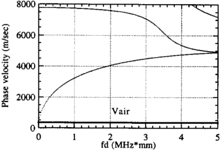
Fig. 1. Dispersion of the Sa and Ao mode Lamb waves in (001) cut silicon plate.
waves in a silicon plate with free boundaries is plotted as In Fig. 1, the phase velocity of the lowest order Lamb a function of the frequency thickness product (fd). It is observed that the phase velocity of the A. mode can be adjusted so that it is close to the sound speed in air (330 m/sec), which is shown on the graph. For example, a 1 pm thick silicon plate will have a phase velocity of 330 m/sec
at 7 MHz. The phase velocity matching can be achieved
using any solid with appropriate thickness. However, the leak rate of the ultrasonic energy is a function of the elastic properties of the plate and most dominantly determined by the density of the plate material. For example, high density materials such as brass and steel have much lower leak rates
as compared t o silicon and aluminum.
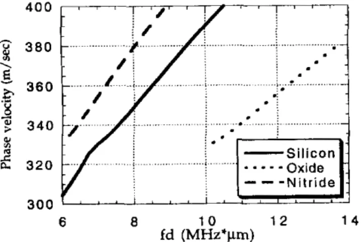
Since these thin dates are much easier t o fabricate wine Any ultrasonic wave propagating on a solid surface radi- micromachining techniques, common micromachined mem- ates energy to the surrounding fluid medium if the phase brane materials are investigated as transducer materials. velocity is larger than the velocity of sound in the fluid. In Fig. 2, part of the A0 mode dispersion curves for 1 pm The perturbation theory predicts the rate of this energy thick silicon, silicon nitride and silicon dioxide plates are transfer very accurately for surface acoustic waves
[6].
Ac- plotted, assuming that the films are not stressed. These cording to this approach the leak rate diverges t o infinity film materials have already been used for Lamb wave d e when the phase velocity of the mode approaches to that vices[S].
The corresponding leak rates for these plates areI
plotted in Fig. 3. As expected, the leak rates have max- ima when the phase velocity is close to 340 m/sec, and they go t o zero when the wave in the plate is subsonic in air. These figures, given in units of dB-X show that 50% of the power in the Lamb wave will be radiated to air in a distance of 5 X for a 1 pm thick silicon plate at
7
MHz. EX- periments confirm these theoretical leak rate calculations.So, once generated, the ultrasonic energy in the Lamb wave is transferred t o air in a very short distance, providing a very efficient transduction mechanism. Since the microma- chining materials have high leak rates, micromachining can be effectively used t o fabricate these devices.
4 0 0 ...~ ... ~ . . . ; ... ~.~~ . ~~ ... .. ; . . . e . . ...
1
: .
: .
:.
. :
. j~.
.... ...~
~ ... . . .... --
Silicon Oxide1
Nitride-
...-.
- - -
~ i & . 2. part of the mode dispersion curves of silicon, silicon nitride and silicon dioxide plates.
0.7
%
0.6 0.5 0.4 0.3 0.2 AS
>,
m 0 Cg
0 . 1<
n
-
6 1 4 6 1 2 1 0fd (MHz'flm)
Lamb
wave
XP
-
outFig. 4. Geometry and coordinates for theoretical analysis.
agatiug in the z direction with a phase velocity of V,, = Referring to Fig. 4, assume that a Lamb wave prop-
VajF/8ir48) in the transmitter plate. The radiakd field is
received by an identical transducer of length 1. The total power radiated from the transmitter to the medium can 11e found as
where v,,(O) is the normal component of the incident par- ticle velocity radiated from the transmitter at z
=
0 and has a variation'"&) = viz(0)e-'P"e-"~. (2)
real and imaginary part (i.e. the leak rate) of the the prop- Z.;, is the acoustic impedance of air and and a are the agation constant in the z direction. It has to be noted that only half of the input power will reach the receiver since half of it is lost from the other side of the trans- mitter plate. This power loss can be prevented by using plate/gap/substrate structures, which will not be discussed in this paper. The Lamb wave amplitude at the receiving plate due to this incident field can be found using the oor- mal mode theory. The expression for the normalized field amplitude at a distance z is given as
In this equation, the v,{ and V z b are the normal component
of particle velocity at the top and bottom surfaces of the plate. The incident normal stress field is denoted by T,t(z') and P,, is the total power per unit width carried by the mode. Since for an antisymmetric mode
. .
Fig. 3. Leak rate8 in dB-X for the same materials in Fig. 2. U z t
=
Vzb Tzt = -Tza (4)the mode amplitude of the Lamb wave at a distance 1 can be written as
111. ANALYSIS OF THE LEAKY WAVE TRANSDUCERS
The purpoae of this section is to find the characteristics e-jp'e-a'lv;tv,,(0)Z,i, of the leaky wave such as optimum dimensions, bandwidth
sonic wave in air is a mode conversion process. Hence it the output in the Wave can be written as
can be analyzed using the methodology developed for bulk mode t o surface wave conversion with appropriate modifi- cations
171.
an(!) =
2 P n n c 0 4 ~ ) (5) etc. The e n e r a transfer from the leaky wave to the
using
the between the mode amplitude andp0dU = lan(WPnn = 1 e
4Pn,c0s(B)2
z -zollv~tlZI~i*(O)IZZ~ir
' ( 6 )
Using the perturbation theory, the leak rate of a Lamb wave mode can be expressed in terms of the mode variables as
face wave since the plate is perturbed by the fluid at both Note that the leak rate is doubled as compared to a sur- surfaces of the plate. Substituting this expression in
Eq.
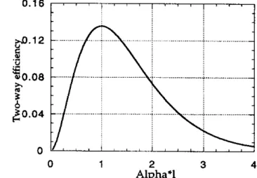
6, the output power can be found in terms of the transducer dimension and the leak rateTo find the optimum dimension of the transducer, the twuway efficiency is defined as the ratio of the output power to total input power. This results in the expression
q ( d ) = (aI)2e-2QL (9)
for the twuway efficiency of the transmitter-receiver sys- tem. Differentiating this expression with respect t o Q!, the maximum efficiency is found as
qmor = 0.135 when a!= 1
(I =
-)At this optimum value the two way insertion loss is about 8.7 dB, which shows the high efficiency of the transducer. The variation of efficiency as a function of transducer length is plotted in Fig. 5. The important conclusion is that the leak rate of the Lamb wave should be high enough so that the transducer has a feasible dimension with rea- sonable insertion loss levels. In case of a l pm thick silicon transducer the optimum dimension is about 14 X (0.66 mm)
at 7.5 MHz, which can be easily micromachimed. The curve
is very similar to the ones obtained for surface wave trans- ducers and shows the importance of the transducer size for generic mode conversion based systems, a fact that is often ignored in Lamb wave applications.
Using the efficiency vs. transducer size and leak rate variation with frequency curves, one can 6nd the band- width of a transducer for a given dimension.
In
Fig. 6 the insertion loss of a 1 pm thick silicon transducer is plot- ted as a function of frequency. The optimum dimension of 0.66 mm results in a 35% fractional bandwidth. Using a larger transducer one can achieve larger bandwidths due to shape of the efficiency curves and avoiding the lowhe-
quency cut-off in the subsonic regime. As an example, a 1.32 mm transducer can have a 78 % fractional bandwidth, which is appropriate for many pulse echo applications.
1
Q (10)
IV. EXPERIMENTAL RESULTS
A leaky wave transducer is constructed using an 18 pm thick (001) silicon plate which is epoxy bonded to a
PZT-
transducer is polarized in the radial direction,
has
a thick- 5H ring with 2.3 cm diameter as shown in Fig. 7. The ness of 1.3 mm, and the coupling to the Ao mode is achieved through the dS1 coefficient. With this configuration the0.16 / ' ' ' 1 ' ' ' 1 " .
Fig. 5. Variation of the efficiency of the leaky wave t r a d u c e r with transducer length-leak rate product.
--+/-I=1.32mm
(28
larndda @%Hz) ..__,__.___. i ... ; ... j ... j ... j ...~
~ . . , i , . . i . . , i . . . i , . .
8
IO
12 14 16 1device has 15% fractional bandwidth around 580 kHz. As depicted in Fig. 7 Lamb waves generated at the transducer- plate contact converge to the center of the plate while leak- ing ultrasonic waves to air. This results in a self l i e focus- ing device.
In Fig. 8, single shot digitized received signal is plotted when the transducers are facing each other. Total inser- tion
loss
is around 55 dB for these suboptimum devices. Although the dynamic range is not large, through t r a m mission measurements can be done on a thin plate of steel show transmission losses in the 40 dB range which is much (25 pm) and copy paper (100 pm). These experiments smaller than the normal incidence experiments. This is the result of the mode conversion in these thin plates. When an 18 pm thick silicon plate is used in the experiment, the transmission loss is only 17 dB, since the plate is well phase matched to the leaky waves.The focusing and imaging ability of the device is also
- 0 . 6 " " 1 " ' 1 ' " 1 " ' 1 ' " i
0 20 4 0 6 0 8 0 1 0 0
Time (wsec)
Fig. 8. Digitized transmjtted signal with 9 mm separation between
transducers.
measured using a scanning imaging system. Fig. 9 shows straight edge is scanned. The 3 dB resolution of the trans- the amplitude variation of the received signal when a ducer is approximately 1 mm, which is less than 2 wave- lengths in air. In Fig. 10, the transmission image through a 1 mm diameter hole in 25 pm thick steel plate is shown. The image size is 1 cm x 1 cm. The high resolution and the d c i e n c y of mode conversion and high resolution imaging interference fringes of
Lamb
waves in the plate indicate the capability of the transducers." ' I " ' . ... ...
-
J ... ... 1 " ' 1 " ' Distance (mm) 12 16 2 5 W. \ I 2oW ... ... ;;.. ..\ ..."
a ... ... Fa
l,,
, l , , \ , , , l , ,,l
... ~ ... n"
0 4 8 12 16 Distance (mm) V. CONCLUSIONLeaky Lamb waves in thin plates provide an efficient means to couple ultrasonic energy to air. The theoretical analysis presented in this paper shows that it is possible to achieve both high efficiency and wide bandwidth ultrasonic analysis also shows that it feasible to fabricate these trans- wave transduction using leaky wave air transducers. The
on large scale devices indicate that leaky wave transduc- ducers using micromachining techniques. The experiments ers can be used in many ultrasound imagmg and sensing applications in a i r in a wide frequency range.
VI. ACKNOWLEDGMENTS
search.
This work is supported by the US Office of Naval Re-
REFERENCES
[I] W k . Grandia and C.M. Fortunko. 'NDE Application of Air-
Coupled Ultraonic Ransducers," i n Pmceedinqs of 1994 IEEE L'ltmsontcs Symposium, pp. 697-709, 1995.
121 D.IV. Schindel and D . A . Hutchins. ".$pplications of microma- chined capacitance transducers in air-coupled ultrasonics and nondestructive evaluation," in IEEE Trans. UFFC, Vol. 42 (1995). pp. 51-58, no. l. January 1995.
[31 M.1. Halier and B.T. Khuri-'rbkub, "-4 surface micromachined eiectro$tacic ultraonic air transducer," in IEEE Tmns. UFFC, 141 I. Ladabaurn. D. Spoiianski and B.T. Khuri-Yakub "Microma-
\oi. 43 (1996), pp. 1-6. no. 1, January 1996.
chined u l t r w n i c transducers: 11.1 M H z transmission in air and
more," in Appl. Phys. L e t t . , Vol. 68 (1996), pp. 7-9. no. I , January [S] H. Dabirikhah and C.W. Turner. "Leaky plate wave airborne
1996.
dtmsonic transducer," in Electmnic Lett., Vol. 30 (1994). pp.
1549-50. no. 18, September 1994.
161 B..A. Auld. Acoustic Fields and Waver in Solids. Kriener Pub
[E] R.M. White, P.J. Wicher. 5.W. Wenrel and E. Zeiies "Plate- processing, Prentice Hall. 1987.
made " I t c a o n i C osciliatnr J ~ ~ S O T S . " in IEEE Tmns. UFFC. Vol.
Fig. 9. Line scan of a straight edge between the transducers.