POWER-SOURCE-AWARE ADAPTIVE
ROUTING IN WIRELESS SENSOR
NETWORKS
a dissertation submitted to
the department of computer engineering
and the Graduate School of engineering and science
of bilkent university
in partial fulfillment of the requirements
for the degree of
doctor of philosophy
By
Metin Tekkalmaz
July, 2013
I certify that I have read this thesis and that in my opinion it is fully adequate, in scope and in quality, as a dissertation for the degree of Doctor of Philosophy.
Assoc. Prof. Dr. ˙Ibrahim K¨orpeo˘glu (Advisor)
I certify that I have read this thesis and that in my opinion it is fully adequate, in scope and in quality, as a dissertation for the degree of Doctor of Philosophy.
Prof. Dr. ¨Ozg¨ur Ulusoy
I certify that I have read this thesis and that in my opinion it is fully adequate, in scope and in quality, as a dissertation for the degree of Doctor of Philosophy.
I certify that I have read this thesis and that in my opinion it is fully adequate, in scope and in quality, as a dissertation for the degree of Doctor of Philosophy.
Assoc. Prof. Dr. U˘gur G¨ud¨ukbay
I certify that I have read this thesis and that in my opinion it is fully adequate, in scope and in quality, as a dissertation for the degree of Doctor of Philosophy.
Assoc. Prof. Dr. Ahmet Co¸sar
Approved for the Graduate School of Engineering and Science:
Prof. Dr. Levent Onural Director of the Graduate School
ABSTRACT
POWER-SOURCE-AWARE ADAPTIVE ROUTING IN
WIRELESS SENSOR NETWORKS
Metin Tekkalmaz
Ph.D. in Computer Engineering
Supervisor: Assoc. Prof. Dr. ˙Ibrahim K¨orpeo˘glu July, 2013
A wireless sensor network (WSN) is a collection of sensor nodes distributed over an area of interest to accomplish a certain task by monitoring environmental and physical conditions and sending the collected data to a special node called sink. Most studies on WSNs consider nodes to be powered with irreplaceable bat-teries, which limits network lifetime. There are, however, perpetual power source alternatives as well, including mains electricity and energy harvesting mecha-nisms, which can be utilized by at least some portion of the sensor nodes to further prolong the network lifetime.
Our aim here is to increase the lifetime of such WSNs with heterogeneous power sources by centralized or distributed routing algorithms that distinguish battery- and mains-powered nodes in routing, so that energy consuming tasks are carried out mostly by mains-powered nodes. We first propose a framework for a class of routing algorithms, which forms and uses a backbone topology consisting of all mains-powered nodes, including the sinks, and possibly some battery-powered nodes, to route data packets. We propose and evaluate a set of centralized algorithms based on this framework, and our simulation results show that our algorithms can increase network lifetime by up to more than a factor of two. We also propose a fully distributed power-source-aware backbone-based routing algorithm (PSABR) that favors mains-powered nodes as relay nodes. We validate and evaluate our distributed algorithm with extensive ns-2 simulations and our results show that the proposed distributed algorithm can enhance network lifetime significantly with a low control messaging overhead.
Besides wireless technology independent routing solutions, we also propose a technology specific power-source-aware routing solution (PSAR) for sensor and
v
ad hoc networks which use 802.15.4/ZigBee as the wireless technology. Our so-lution is fully distributed, tree-based, and traffic-adaptive. It utilizes some pro-tocol specific properties of ZigBee, such as distributed and hierarchical address assignment, to eliminate battery-powered nodes on the routing paths as much as possible. To validate and evaluate our ZigBee-specific algorithm, we first imple-mented ZigBee extensions to ns-2 simulator and then impleimple-mented and simulated our protocol in this extended ns-2 environment. Our results show that the pro-posed algorithm operates efficiently and can increase network lifetime without increasing the path lengths significantly, compared to the default ZigBee routing algorithm.
Keywords: wireless sensor networks, network lifetime, routing, heterogeneous net-works, backbone, power-source-aware, mains-powered, ZigBee, energy-efficiency.
¨
OZET
KABLOSUZ ALGILAYICI A ˘
GLAR ˙IC
¸ ˙IN G ¨
UC
¸
KAYNA ˘
GI B˙IL˙INC
¸ L˙I DEV˙INGEN YOL ATAMA
Metin Tekkalmaz
Bilgisayar M¨uhendisli˘gi, Doktora Tez Y¨oneticisi: Do¸c. Dr. ˙Ibrahim K¨orpeo˘glu
Temmuz, 2013
Kablosuz algılayıcı a˘glar, belli bir amacı ger¸cekle¸stirmek i¸cin ilgilenilen b¨olgeye da˘gıtılmı¸s algılayıcı d¨u˘g¨umlerden olu¸sur. Bu d¨u˘g¨umler ¸cevresel ve fiziki ¸sartları izleyerek toplanan veriyi belli bir merkezi d¨u˘g¨ume g¨onderir. Kablosuz algılayıcı a˘glar ile ilgili ¸co˘gu ¸calı¸smada algılayıcı d¨u˘g¨umlerin g¨uc¨un¨un a˘g ya¸sam s¨uresini sınırlayan de˘gi¸stirilemez piller ile sa˘glandı˘gı varsayılmaktadır. Di˘ger taraftan, algılayıcı d¨u˘g¨umlerin en az bir kısmına g¨u¸c sa˘glayabilecek ve b¨oylece a˘g ya¸sam s¨uresini uzatabilecek ¸sebeke elektri˘gi, enerji hasadı mekanizmaları gibi daimi g¨u¸c kaynakları da bulunmaktadır.
Burada amacımız pil ve ¸sebeke elektri˘gi ile beslenen farklı tipteki algılayıcı d¨u˘g¨umlere sahip bu tarz heterojen kablosuz algılayıcı a˘gların ya¸sam s¨uresini merkezi ve da˘gıtık yol atama algoritmaları kullanarak ve bu esnada fazla enerji gerektiren i¸sleri ¸sebeke elektri˘gi ile beslenen d¨u˘g¨umlere atayarak uzatmaktır. ˙Ilk olarak bir sınıf yol atama algoritması ¨uretiminde kullanılabilecek bir ¸cer¸ceve ¨
oneriyoruz. Uretilen algoritmaların ortak ¨¨ ozelli˘gi ¸sebeke elektri˘gi ile besle-nen d¨u˘g¨umleri, hedef d¨u˘g¨um¨u ve gerekiyorsa pil ile beslenen bazı d¨u˘g¨umleri i¸ceren bir omurga olu¸sturarak veriyi aktarmak i¸cin bu omurgayı kullanmalarıdır. Sim¨ulasyon sonu¸clarımız bu ¸cer¸ceveyi kullanarak ¨uretti˘gimiz merkezi algorit-maların a˘g ya¸sam s¨uresinde iki kata kadar artı¸s sa˘gladı˘gını g¨ostermi¸stir. Ayrıca bu ¸calı¸smada veri iletimi i¸cin ¸sebeke elektri˘gi ile beslenen d¨u˘g¨umlere ¨oncelik veren g¨u¸c kayna˘gı bilin¸cli, omurga temelli ve tam da˘gıtık bir yol atama algoritması da ¨
oneriyoruz. ¨Onerdi˘gimiz bu algoritmayı ge¸cerlemek ve de˘gerlendirmek amacıyla ns-2 ortamını kullanarak elde etti˘gimiz sim¨ulasyon sonu¸cları g¨ostermektedir ki, algoritmamız d¨u¸s¨uk bir ek haberle¸sme y¨uk¨u ile a˘g ya¸sam s¨uresini belirgin ¸sekilde arttırmaktadır.
vii
Bu ¸calı¸smada, bahsi ge¸cen teknoloji ba˘gımsız yol atama ¸c¨oz¨umlerimizin yanısıra, 802.15.4/ZigBee kablosuz a˘g teknolojisine ¨ozel, g¨u¸c kayna˘gı bilin¸cli, tam da˘gıtık, a˘ga¸c tabanlı ve trafi˘ge uyumlanabilen bir yol atama ¸c¨oz¨um¨u de ¨
onermekteyiz. Onerdi˘¨ gimiz yol atama ¸c¨oz¨um¨u pil ile beslenen d¨u˘g¨umlerin haberle¸sme yolları ¨uzerinde yer almasını m¨umk¨un oldu˘gunca ¨onlemek amacıyla, da˘gıtık ve hiyerar¸sik a˘g adresi atama mekanizması gibi ZigBee protokol¨une ¨ozel yetenekleri kullanmaktadır. ZigBee teknolojisine ¨ozel algoritmamızı ge¸cerlemek ve de˘gerlendirmek amacıyla ilk olarak ZigBee protokol¨un¨un ihtiya¸c duydu˘gumuz kısımlarını, daha sonra da ¨onerdi˘gimiz algoritmayı ns-2 sim¨ulasyon ortamında ger¸cekledik. Hazırladı˘gımız ns-2 sim¨ulasyon ortamını kullanarak elde etti˘gimiz sonu¸clar, ZigBee tanımında yer alan yol atama y¨ontemi ile kar¸sıla¸stırıldı˘gında, ¨
onerdi˘gimiz algoritmanın yol uzunluklarını arttırmadan a˘g ya¸sam s¨uresini arttırabildi˘gini g¨ostermi¸stir.
Anahtar s¨ozc¨ukler : kablosuz algılayıcı a˘glar, a˘g ya¸sam s¨uresi, yol atama, hete-rojen a˘glar, omurga, g¨u¸c kayna˘gı bilin¸cli, ¸sebeke elektri˘gi ile beslenen, ZigBee, enerji verimi.
Acknowledgement
First of all, I would like to express my sincere gratitudes to my supervisor Assoc. Prof. Dr. ˙Ibrahim K¨orpeo˘glu. I am grateful for his invaluable support for all these long years, which made this thesis come true. His encouraging and positive attitude has always kept me walking.
I would like to thank to the thesis committee members Prof. Dr. Ozg¨¨ ur Ulusoy and Dr. Defne Akta¸s for their valuable comments for the past six years. I would also like to thank to the thesis jury members Prof. Dr. Tolga Mete Duman, Assoc. Prof. Dr. U˘gur G¨ud¨ukbay, and Assoc. Prof. Dr. Ahmet Co¸sar for kindly accepting to spend their valuable time and to evaluate this work.
I would like to express my appreciation to ASELSAN A.S¸. for the understand-ing and support durunderstand-ing my academic studies. I also want to thank to people I work with for the joy they bring to my life making my work life together with academic life a pleasureful experience.
I would like to thank to my parents and grandparents for raising me with all their love. I would not be the person who I am without their never-ending support. I would also like to thank to my brother Sezgin. Despite the physical distance between us throughout our lives, he always cheers me up.
And most of all, my beloved wife Tu¸ce who has lived every stage of this long journey with me. Thank you for bearing with me for all this time. I cannot express how valuable your support has been to me, I love you. And my son Dorukhan Aral. I can only imagine being son of a daytime software developer and nighttime PhD candidate. I apologize for the time I have stolen from you for the last five years. And the newcomer of the family, my daughter Pelin. You are already five months old without a proper father. I promise to be a better father and husband from now on.
Contents
Contents ix
List of Figures xii
List of Tables xvii
1 Introduction 1
1.1 Contributions . . . 8
1.2 Outline of the Thesis . . . 10
2 Related Work 11 2.1 Energy Conservation . . . 11 2.2 Routing . . . 13 2.3 Power Sources . . . 15 2.4 Heterogeneity . . . 16 2.5 ZigBee . . . 17
CONTENTS x
Wireless Sensor Networks 20
3.1 Our Routing Algorithm Framework . . . 21
3.2 Sample Centralized Algorithms Based on Our Framework . . . 26
3.3 Evaluation of the Proposed Approach . . . 30
3.4 Conclusions . . . 34
4 A Distributed Algorithm for Power-Source-Aware Routing in Wireless Sensor Networks 36 4.1 Our Distributed Routing Algorithm: PSABR . . . 37
4.1.1 Messages . . . 38
4.1.2 Sample Backbone Construction . . . 41
4.1.3 Behavior . . . 44
4.1.4 Analysis . . . 57
4.2 Performance Evaluation . . . 59
4.2.1 Simulation Implementation Details . . . 59
4.2.2 Visualization of Simulations . . . 63
4.2.3 Simulation Parameters . . . 64
4.2.4 Simulation Results . . . 66
4.3 Conclusions . . . 75
5 Power-Source-Aware Routing in ZigBee Networks 76 5.1 The ZigBee Standard . . . 77
CONTENTS xi
5.1.1 A Brief Summary . . . 77
5.1.2 ZigBee Address Assignment . . . 79
5.2 Our Power-Source-Aware Routing Algorithm: PSAR . . . 81
5.2.1 The Algorithm Details . . . 83
5.2.2 Implementation . . . 88
5.2.3 Analysis . . . 90
5.3 Simulation Results . . . 92
5.4 Conclusions . . . 107
6 Conclusions and Future Work 108
List of Figures
1.1 (a) Visibility graph, (b) secondary graph, (c) spanning tree on the secondary graph, (d) mapping to the original graph, and (e) rout-ing tree. . . 4
1.2 (a) Visibility graph, (b) initial routing tree, and (c) routing tree after reconfiguration. . . 7
3.1 (a) Visibility graph, (b) a spanning tree on the mains-powered node connectivity graph, (c) backbone, and (d) routing tree graph (reprinted from Fig. 1 of [1] c 2010 IEEE). . . 23 3.2 A portion of a sample wireless sensor network. . . 26
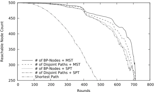
3.3 Number of rounds passed vs. number of nodes reachable from the sink (mains-powered node ratio: 20%) (reprinted from Fig. 2 of [1]
c
2010 IEEE). . . 32 3.4 Number of rounds passed vs. average energy consumption per
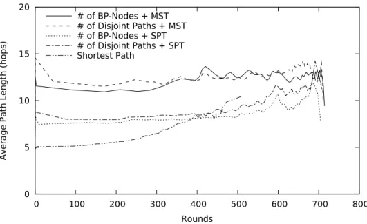
round (mains-powered node ratio: 20%) (reprinted from Fig. 3 of [1] c 2010 IEEE). . . 33 3.5 Number of rounds passed vs. average path length to the sink
(mains-powered node ratio: 20%) (reprinted from Fig. 4 of [1] c
LIST OF FIGURES xiii
3.6 Mains-powered node ratio vs. network lifetime (reprinted from
Fig. 5 of [1] c 2010 IEEE). . . 35
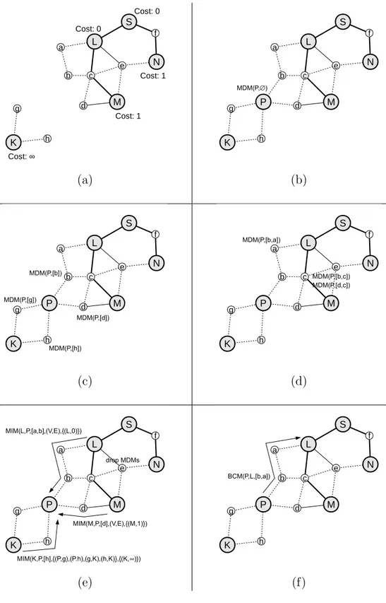
4.1 Backbone construction (1 of 2). . . 42
4.2 Backbone construction (2 of 2). . . 43
4.3 Finite state machine for mains-powered nodes. . . 46
4.4 Finite state machine for battery-powered nodes. . . 53
4.5 Mobile node architecture in ns-2. . . 60
4.6 Visual output of a sample simulation run at different points in time. 65 4.7 Number of reachable nodes over time [n = 150, m = 20%]. . . . 66
4.8 (a) Average indegree, (b) number of packets transmitted over time, (c) energy consumption of battery-powered nodes, and (d) total residual energy of battery-powered nodes [n = 150, m = 20%]. . . 67
4.9 Node counts as new nodes arrive and the network is constructed [n = 300, m = 25%]. . . 69
4.10 Network lifetime (assuming lifetime is the time passed until half of the nodes become unreachable from the sink) depending on (a) node count [m = 20%, ρ = 100%], (b) mains-powered node ratio [n = 150, ρ = 100%], and (c) density [n = 150, m = 20%]. . . 70
4.11 Network lifetime (assuming lifetime is the time passed until the first node death) depending on (a) node count [m = 20%, ρ = 100%], (b) mains-powered node ratio [n = 150, ρ = 100%], and (c) density [n = 150, m = 20%]. . . 71
4.12 Number of control packets required to construct the network [m = 20%]. . . 72
LIST OF FIGURES xiv
4.13 Lifetime and average path length to sink for different sink counts [n = 150, m = 20%]. . . 73
4.14 Number of messages (MDM and MIM) required to discover a peer [n = 300, m = 20%]. . . 74
5.1 ZigBee protocol stack (reprinted from Fig. 1 of [2] c Springer Science+Business Media, LLC 2012, with kind permission from Springer Science and Business Media). . . 78
5.2 ZigBee distributed address assignment (reprinted from Fig. 2 of [2] c
Springer Science+Business Media, LLC 2012, with kind permis-sion from Springer Science and Business Media). . . 81
5.3 Modifying the ZigBee tree topology to change communication paths (reprinted from Fig. 3 of [2] c Springer Science+Business Media, LLC 2012, with kind permission from Springer Science and Business Media). . . 82
5.4 Percent reduction in traffic load on the battery-powered devices (x-axis: battery-powered device ratio, y-axis: percent reduction) (reprinted from Fig. 5 of [2] c Springer Science+Business Media, LLC 2012, with kind permission from Springer Science and Busi-ness Media). . . 94
5.5 Average reduction in traffic load on the battery-powered devices for the network sizes of 10, 40, and 70 devices and communicat-ing pair ratios of 10%, 30%, and 50% (reprinted from Fig. 6 (a) of [2] c Springer Science+Business Media, LLC 2012, with kind permission from Springer Science and Business Media). . . 96
LIST OF FIGURES xv
5.6 Total reduction in traffic load on the battery-powered devices for the network sizes of 10, 40, and 70 devices and communicating pair ratios of 10%, 30%, and 50% (reprinted from Fig. 6 (b) of [2]
c
Springer Science+Business Media, LLC 2012, with kind per-mission from Springer Science and Business Media). . . 97
5.7 Percent reduction in traffic load on the battery-powered devices and number of configurations over time for the network size of 40 devices and communicating pair ratio of 30% (reprinted from Fig. 7 of [2] c Springer Science+Business Media, LLC 2012, with kind permission from Springer Science and Business Media). . . 98
5.8 Percent reduction in traffic load on the battery-powered devices for the dynamic traffic case (x-axis: battery-powered device ratio, y-axis: percent reduction) (reprinted from Fig. 8 of [2] c Springer Science+Business Media, LLC 2012, with kind permission from Springer Science and Business Media). . . 99
5.9 Percent reduction in standard deviation of traffic load on the batterpowered devices (x-axis: batterpowered device ratio, y-axis: percent reduction) (reprinted from Fig. 9 of [2] c Springer Science+Business Media, LLC 2012, with kind permission from Springer Science and Business Media). . . 101
5.10 Percent reduction in average path lengths between communicat-ing devices (x-axis: battery-powered device ratio, y-axis: per-cent reduction) (reprinted from Fig. 10 of [2] c Springer Sci-ence+Business Media, LLC 2012, with kind permission from Springer Science and Business Media). . . 102
5.11 Packet drop rate (x-axis: battery-powered device ratio, y-axis: drop rate in packets per second) (reprinted from Fig. 11 of [2]
c
Springer Science+Business Media, LLC 2012, with kind per-mission from Springer Science and Business Media). . . 104
LIST OF FIGURES xvi
5.12 Ratio of control packet traffic to data traffic (x-axis: battery-powered device ratio, y-axis: control packet ratio) (reprinted from Fig. 12 of [2] c Springer Science+Business Media, LLC 2012, with kind permission from Springer Science and Business Media). . . . 105
5.13 Change in control packet count per reconfiguration with respect to network size (reprinted from Fig. 13 of [2] c Springer Sci-ence+Business Media, LLC 2012, with kind permission from Springer Science and Business Media). . . 106
List of Tables
4.1 Summary of the messages. . . 39
4.2 Variables and expressions. . . 45
4.3 Simulation parameters. . . 64
5.1 802.15.4 and ZigBee commands utilized in the implementation of the proposed algorithm. . . 89
5.2 Total traffic in KB for different network sizes and communicating pair ratios. . . 97
Chapter 1
Introduction
A wireless sensor network (WSN) is a collection of nodes, which are capable of sensing, data processing, and wireless communication, distributed over an area of interest to accomplish a certain task. Nodes in a WSN monitor environmental and physical conditions and send the collected data to a special node, called sink or base station, usually in a multi-hop fashion. Therefore, the main purpose of a WSN is basically information gathering and delivery.
Typically, a sensor node consists of a processing unit, a wireless radio, and at least one sensor. Sensing capabilities of the nodes vary depending on the application, and different types of sensors are able to sense different physical phenomenon such as temperature, moisture, smoke, vibration, pressure, light, and sound. Continuous advances in wireless technology, sensing devices and low power electronics make WSNs a feasible solution for a wide range of applications. These applications include, but not limited to, habitat and environment monitoring, air conditioning control in buildings, collecting vital statistics of patients, controlling moisture level of soil in agriculture, industrial process monitoring and control, intrusion detection, target tracking, home automation, building evacuation in emergency conditions, and traffic control. Depending on the application type and coverage, number of nodes in a WSN can vary from a few to several thousands. While some of the applications require careful manual placement of nodes, in the others it might be possible to throw the nodes from air vehicles in large quantities.
Batteries have been the natural choice of power source in WSNs to facili-tate ease of node deployment. On the other hand, limited energy of batteries restricts WSN lifetime. In a WSN composed of battery-powered nodes, replacing or recharging batteries is vital for the continuity of the operation. But most of the time, it is a costly process considering the high number of sensor nodes and worse, it might be impossible due to reasons such as safety in military applica-tions or harsh environmental condiapplica-tions. Historically, majority of the studies on WSNs assume that the nodes are battery-powered and extending the network lifetime has been one of the most studied subjects on WSNs. In general, the studies attack to a specific layer (e.g., physical, data link, network, transport) on the protocol stack, or they follow a cross-layer approach. Some of the studies try to increase the lifetime of individual nodes, and others try to increase the network lifetime as a whole.
Although most of the studies assume that sensor nodes are battery-powered, there are several studies showing that alternative energy sources exist [3][4][5]. Capacitors, fuel cells, heat engines, and beta voltaic systems are listed as energy sources with different capacities, that can be used to power sensor nodes, besides regular batteries. Although some of these energy sources last longer than the others, their energy depletes eventually as well. There are also alternatives to power sensor nodes continuously. One such alternative is to wirelessly transmit energy to the sensor nodes from a nearby energy-rich power source using radio frequency (RF) signals. A more promising perpetual power source alternative is energy harvesting, which basically is the process of converting ambient energy into usable electrical energy. Energy harvesting by itself is not a new research area, but its use in WSNs has gained popularity recently, as a result of the advances in the field enabling more efficient, smaller, and cheaper energy harvesting systems.
Mains electricity (power line) is another possible continuous power source al-ternative for sensor nodes. Although it seems to be in contradiction with the nature of wireless sensor nodes and networks, there is no reason for at least some of the sensor nodes not to benefit from the continuous energy source of the facil-ity if they are already next to power lines. This is especially the case for indoor applications, where the nodes are deployed in houses, offices, buildings, factories,
etc. In such a scenario, mains-powered nodes would be preferred wherever possi-ble to reduce maintenance costs, and battery-powered nodes would be used where installing power lines is costly or impractical.
In this thesis, our aim is to increase the lifetime of WSNs composed of nodes with heterogeneous power sources. We especially focus on WSNs composed of battery- and mains-powered nodes. But our study can easily be extended to WSNs in which some of the nodes have finite energy and the others are fed by continuous power sources, like energy harvesting systems. More details on possible continuous power sources are provided in Chapter 2. In the rest of the thesis, terms battery-powered and mains-powered are going to be used to refer class of nodes with finite and continuous power sources, respectively.
Our basic approach to increase the lifetime of WSNs is to make related algo-rithms power-source-aware in which energy consuming tasks, such as routing, co-ordination, and data processing, are mostly carried out by mains-powered nodes. Battery-powered nodes, on the other hand, are mainly responsible for sensing and sending their own data. We assume that all nodes have fixed and identical communication range without loss of generality. We also assume that the nodes are mostly stationary as expected in a WSN.
Firstly, we propose a framework for a class of routing algorithms. The reason we call it a framework is that some parts of it have several alternatives, therefore depending on the choice, different algorithms can be obtained. Our framework aims to form a backbone topology consisting of all mains-powered nodes, in-cluding the sinks. The backbone may also include battery-powered nodes, as required, if the mains-powered nodes do not form a connected topology. The resulting backbone is actually a tree rooted at the sink if there is a single sink, or a forest if there are multiple sinks. The remaining sensor nodes are connected to this backbone structure, either directly or through multiple-hops. The data packets produced by the sensor nodes are routed through this backbone structure towards the sinks.
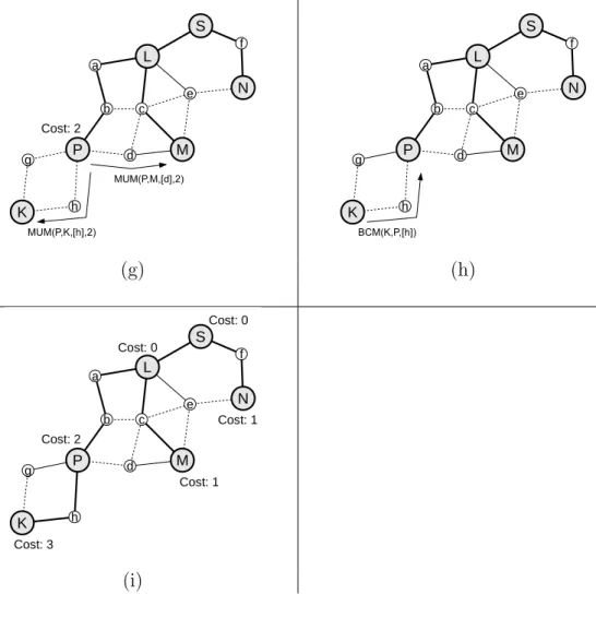
Given a visibility (reachability) graph representing a WSN, where sensor nodes are the vertices and wireless links are the edges, the proposed framework first
S S S (a) (b) (c) S S battery-powered node mains-powered node (d) (e)
Figure 1.1: (a) Visibility graph, (b) secondary graph, (c) spanning tree on the secondary graph, (d) mapping to the original graph, and (e) routing tree.
reduces the original graph to a secondary graph: vertices representing the mains-powered nodes in the original graph constitutes the vertices of the secondary graph and there is an edge between the vertices of the secondary graph if the length of the shortest path between the corresponding vertices of the original graph is below a threshold. Then a spanning tree is found on the secondary graph. Using this spanning tree, the backbone on the original graph is determined, by replacing the edges in the spanning tree by the corresponding paths in the original graph. Finally, the rest of the nodes connect to the backbone to form a routing tree.
Figure 1.1 shows the graphs related to a sample network at different steps of the algorithm framework during its execution. Figure 1.1 (a) is the visibility
graph of the sample network in which the battery-powered nodes are represented by rings whereas the mains-powered nodes are represented by black circles. The sink is marked with an S. Figure 1.1 (b) is the secondary graph extracted by the algorithm framework. In this sample case, we assume the maximum hop distance between the mains-powered nodes used while extracting the secondary graph is 2. Figure 1.1 (c) depicts a spanning tree on the secondary graph and Figure 1.1 (d) shows the backbone obtained by mapping the spanning tree on the secondary graph to a tree on the original graph. Finally, Figure 1.1 (e) presents the routing tree obtained by connecting the rest of the nodes to the backbone.
In order to show the effectiveness of our approach and framework, we carried out extensive simulation experiments. In the experiments, we assumed that a central node (possibly the sink) has the global visibility graph, hence the backbone can be computed centrally. Our experiment results show that the centralized algorithms based on our proposed framework are able to increase the network lifetime by up to more than a factor of two, compared to the case in which battery- and mains-powered nodes are not differentiated.
Secondly, we present a power-source-aware backbone-based distributed rout-ing algorithm (PSABR) based on the framework we propose. We give the detailed design of our distributed algorithm including all control messages and node be-haviors in the form of pseudo-codes and finite state machines. We implemented the algorithm in ns-2 [6] network simulation environment completely, and run simulations to validate its correctness and robustness, as well as to measure its effectiveness and efficiency.
So far, our proposed methods are technology independent: any wireless tech-nology providing one-hop wireless communication and an addressing mechanism to distinguish nodes can use our methods. But there are already several specific wireless communication technologies targeting especially WSNs such as 6LoW-PAN [7], ZigBee [8], and Bluetooth Low Energy [9]. Algorithms designed for a specific wireless communication technology can benefit from the features the technology provides, but the algorithm should also comply with the restrictions and constraints the technology imposes, such as maximum number of neighbors,
types and roles of devices defined, address assignment mechanism and scheme, routing method, etc.
Thirdly, besides our wireless technology independent solutions, we also focused on and worked with a specific wireless technology, namely ZigBee, and applied our basic approach of distinguishing nodes based on their power sources while creating logical topologies and routing structures. The ZigBee standard is built on the IEEE 802.15.4 standard [10], which shares similar goals. ZigBee defines the application layer and the network layer, whereas IEEE 802.15.4 defines the medium access control layer and the physical layer. Both tree and mesh topologies are possible in a ZigBee network. The ZigBee standard defines a distributed and hierarchical address assignment mechanism and a routing method that depends on this addressing mechanism.
In our study related to ZigBee networks, we concentrate on tree topologies with the distributed address assignment mechanism enabled. We propose a dis-tributed, dynamic, and traffic-load-aware routing algorithm to be used for sensor and ad hoc networks. The algorithm is fully distributed and forwards the packets according to the tree-based hierarchical addresses of ZigBee nodes. It considers traffic load in the network and in this way tries to use less number of battery-powered nodes on the paths between heavily communicating nodes. Each node in the network monitors the traffic it forwards and reconfigures the current topology if the data forwarded by battery-powered nodes would be less in an alternative topology compared to the current topology. Thanks to the distributed address assignment mechanism of the ZigBee standard, we can compute the addresses of the intermediate nodes given addresses of the source and the destination nodes, hence the nodes can compare the alternative topologies with minimal communi-cation overhead.
In Figure 1.2, we present a sample reconfiguration scenario. Given a network as in Figure 1.2 (a), where the rings, circles, and edges represent battery-powered nodes, mains-powered nodes and the wireless links between the nodes, respec-tively and the PAN (personal area network) coordinator is marked with a C; assume that the initial routing tree is as shown in Figure 1.2 (b) where the edges
C + + # # C + + # # C (a) (b) (c)
Figure 1.2: (a) Visibility graph, (b) initial routing tree, and (c) routing tree after reconfiguration.
represent the logical links of the routing tree. Also assume that the node pairs marked with + and # communicate with each other, hence the edges shown with solid lines represent the active links on the routing tree. In Figure 1.2 (b), number of battery-powered nodes on the routing paths is six. If we can recon-figure the routing tree as shown in Figure 1.2 (c), we can reduce the number of battery-powered nodes on the routing paths to three.
Our study on ZigBee networks differs from our previous studies in three re-spects. One, it is technology specific. Two, it assumes point-to-point communi-cation is possible. Three, we do not assume a regular traffic flow between the nodes, that is, rate and end points of the data traffic can change over time. Due to these last two aspects, besides WSNs where traffic is usually many-to-one, it is also suitable for wireless ad hoc networks where traffic is peer-to-peer. It can also be used in wireless sensor and actuator networks (WSANs) where traffic can be both many-to-one and peer-to-peer. In WSANs, data may need to be gath-ered from all sensor nodes to the sink node and also may need to be transported between sensors and actuators. Hence, our ZigBee specific topology control and routing solution can be used for a broad range of ZigBee applications.
We evaluated the proposed ZigBee routing solution again using the ns-2 sim-ulator. For that, we first implemented the ZigBee protocol in ns-2, on top of
the IEEE 802.15.4 implementation which is already available. Then, we embed-ded our protocol to ns-2 and performed extensive experiments. Our results show our routing protocol extends network lifetime compared to the default routing algorithm of ZigBee, which is not traffic-aware and which does not distinguish battery- and mains-powered nodes.
1.1
Contributions
The followings are the contributions of this thesis:
• We propose a backbone-based routing approach to increase WSN lifetime by distinguishing the sensor nodes according to their power sources.
• By following this approach, we propose an algorithm framework for WSNs in which battery- and mains-powered nodes coexist. The framework allows an energy-efficient, backbone-based routing algorithm to be obtained by selecting alternative sub-algorithms, depending on the application require-ments.
• We propose a set of centralized backbone-based routing algorithms obtained using our framework. We showed via simulations that network lifetime can be increased by a factor of two using our algorithms, compared to using a basic algorithm that does not distinguish between battery- and mains-powered nodes.
• We also propose a distributed algorithm for constructing and maintaining a backbone-based routing structure that routes packets from sensor nodes to the sink in an energy-efficient manner and prolongs the network lifetime in this way. We describe the protocol messages used and also provide battery-and mains-powered node behaviors in detail battery-and rigorously by means of pseudo-codes and finite state machines.
• To validate and evaluate our distributed algorithm, we developed a simu-lation environment based on ns-2 and a tool to visualize network topology
and routing relationships among the nodes. This tool can be used in sim-ilar studies with slight modifications. The simulation results show that our power-source-aware distributed routing algorithm can enhance network lifetime significantly compared to a basic shortest-path algorithm that does not distinguish battery- and mains-powered nodes.
• In addition to our wireless technology independent studies, we also propose a novel tree-based routing topology construction and maintenance algo-rithm for ZigBee wireless networks. Besides describing our algoalgo-rithm in every detail, we also show a method to compute the ZigBee network ad-dresses of intermediate nodes between any given source-destination pair, that depends on the distributed address assignment mechanism of ZigBee. Our routing algorithm can utilize mains-powered nodes to reduce packet and energy load on battery nodes. It is also adaptive to changes in traffic patterns.
• To evaluate the performance of our tree-based ZigBee routing algorithm, we again implemented an ns-2 simulation. To do this, we partially implemented the network (NWK) layer of ZigBee into ns-2 environment. Hence, we contributed a new module to ns-2.
• The set of solutions we provide in this thesis are analyzed considering dif-ferent aspects such as:
– centralized vs. distributed algorithms,
– single vs. multiple sinks,
– generic vs. technology-specific approaches,
– continuous dissemination vs. event-driven communication,
1.2
Outline of the Thesis
Organization of the thesis is as follows. In the next chapter we give the related studies in the literature. In Chapter 3, we present a framework for a class of algorithms that basically forms a backbone, mainly composed of mains-powered nodes, to route the data packets. In Chapter 4, we describe a distributed al-gorithm based on this framework in detail. We propose a distributed alal-gorithm specific to ZigBee networks, which shapes the network topology in order to re-duce the data forwarded by the battery-powered devices in Chapter 5. Finally, in Chapter 6, we summarize accomplishments of the thesis along with possible future research directions.
Chapter 2
Related Work
In this chapter, we describe the previous work related to our study on power-source-aware routing in heterogeneous WSNs. We first give studies on energy conservation in WSNs since our aim is to increase the network lifetime by careful use of limited energy of battery-powered nodes. Next, we present studies related to routing in general and backbone routing in particular in wireless ad hoc and sensor networks, since our studies focus on routing and employ a backbone-based routing approach. We also describe some of the studies related to power-source types in WSNs including energy harvesting and discuss studies exploiting node heterogeneity similar to our study. Finally, we present studies related to our ZigBee-specific adaptive routing method that distinguishes nodes with respect to their power-source types to increase network lifetime.
2.1
Energy Conservation
Due to the limited energy resources and mostly unattended nature of WSNs, efficient use of energy to increase the network lifetime has been one of the most studied subjects related to WSNs [11].
In a recent study, Anastasi et al. [12] provide a taxonomy for energy conser-vation techniques in WSNs and present a survey on the related studies based on this taxonomy. At the highest level, the authors classify studies into one of the following categories: approaches employing duty-cycling, data-driven approaches, and mobility-based approaches. The duty-cycling based studies are further classi-fied into two subcategories: topology-control based studies and connection-driven studies. In studies belonging to the topology control subcategory, node redun-dancy is exploited to cover the area as in [13] and [14] or provide the network connectivity using a subset of the nodes as in [15], [16], and [17]. Our study falls into the connection-driven subcategory, since we exploit the redundancy of the nodes in the network to route data packets in an energy-efficient manner. In [12], data-driven approaches are further divided into data reduction [18][19][20] and energy-efficient data acquisition [21][22][23] subcategories. Although we assume that data aggregation (which is a data reduction technique) is possible in our simulations, it is not an integral part of our proposed solutions and our schemes can be used in environments with or without data aggregation.
In another study, Gupta et al. [24] also investigate energy efficiency in WSNs. Authors first discuss methods to reduce energy consumption that can be em-ployed at the MAC (media access control) layer, such as avoiding collisions and overhearing, but the main focus of the study is network layer protocols. Effective routes and efficient route setup and maintenance are given as means of energy efficient routing in WSNs. In our study, we aim at constructing effective routes from the viewpoint of battery-powered nodes, but we also consider efficiency of the route construction.
Yet in another work dealing with energy efficient strategies in WSNs [25], re-lated studies are grouped into four: energy efficient routing [26][27][28], scheduling the nodes’ sleeping state [29][30], topology control by tuning node transmission power [31][32], and reducing the volume of information transferred [33][34]. In some respects [25] resembles similarities with the grouping given in [12], but dif-ferently it considers routing in a separate category. We discuss routing in WSNs in a broader sense in Section 2.2, but here we focus on the energy efficiency as far as routing in WSNs concerned. Multipath routing is given as one of the strategies
to prolong lifetime and employed in studies like [26], [35], [36], and [37]. In our study we take multipath routing into account not as end-to-end multipath rout-ing but rather as multipath routrout-ing between mains-powered nodes. By usrout-ing this method we aim at balancing energy usage of battery-powered nodes connecting mains-powered nodes.
Adaptive hop-by-hop routing is given in [25] as another strategy for energy efficient routing in WSNs. Studies like [27] and [38] try to select paths consuming minimum energy whereas studies like [28] try to use paths with nodes having the highest residual energy. There are also studies which apply a hybrid of these two methods such as [39]. Favoring paths with minimum energy requirement has the disadvantage of depleting energy of common nodes residing on multiple paths. On the other hand, using residual energy while deciding the routing paths requires additional information exchange and can increase the amount of control messages. In some of the studies applying cluster-based routing, cluster heads are elected according to residual energy of the nodes either by one-hop message exchange or by probabilistic methods [40][41][42], to minimize or eliminate message exchange. But they are prone to connectivity problems unless additional precaution is taken, such as increasing node density.
2.2
Routing
Al-Karaki and Kamal [43] investigate different aspects of routing in WSNs and present a survey on the related studies. Authors categorize the routing protocols into three groups according to the network structure. In flat routing, sensor nodes take equal role in routing in the network as in [44][45][26]; in hierarchical routing, a group of the nodes take special role, such as cluster-heads, and coordinate communication between the regular nodes and the sink as in [46][47][48][49]; and finally in location based routing, nodes are addressed based on their locations and data packets are routed accordingly as in [15][50][51]. Hierarchical routing methods facilitate scalability and energy efficiency and have better potential to exploit node heterogeneity. Our proposed method based on backbone routing
best fits into the hierarchical routing category and has two levels of hierarchy: nodes forming the backbone, which are mostly mains-powered, and rest of the nodes, which are battery-powered.
As Simplot-Ryl et al. enumerate in [52], backbone-based approaches for data dissemination and gathering are rather well-studied. As in other related studies, in [52], backbone is considered to be either neighbor- or area-dominating set of a network. In the former, all nodes are either part of the backbone or in one-hop distance of it, and in the latter, the whole area is in the sensing range of the nodes constituting the backbone. Since finding the minimum connected dominating set (CDS) is NP-complete, approaches in the literature are based on centralized or distributed heuristics. Although centralized algorithms can provide bounds on the size of CDS, such as in [53], they require global information, increasing the messaging overhead.
Localized backbone-based approaches, in which only a limited neighborhood information is shared, are based on either deterministic or probabilistic algo-rithms. Span, presented in [15], is an example of probabilistic algoalgo-rithms. In Span, a node either sleeps or takes part in the backbone randomly, based on its residual energy and the benefit to its neighbors if it stays awake. In a similar al-gorithm called EAD [54], Boukerche et al. try to find a spanning tree with many leaf nodes. In EAD, nodes with higher residual energy have a higher chance of not being a leaf-node. As another distributed algorithm, in ASCENT [16], nodes participate in sensing and routing tasks according to the packet-losses due to lack of relay nodes and packet-losses due to collisions. Hence, the aim is to keep only a subset of the nodes alive to preserve energy.
Cell-based approaches, which are also CDS-based, are employed in different studies including [13] and [55]. In both studies the area is divided into cells and only a single node in each cell is kept alive for routing. The major drawback of these studies is that they need to know the locations of the nodes. In the studies mentioned so far, the aim is to find a CDS. Differently in [56], the authors present different protocols that ensure k-connectedness of dominating sets, for the sake of fault tolerance. In a different study that take fault tolerance into account,
Kashyap et al. [57] add relay nodes to a WSN in order to provide a k-connected backbone.
In our study, different from the previous studies based on backbone construc-tion, we assume that the sensor nodes are heterogeneous as far as their power sources are considered. Although studies, such as [53] and [15], that take residual energy into account, can be applied for this case, prior knowledge of different power-source types enables specialized solutions, since the energy of the nodes change in time but their power-source types do not. In this study, we also adapt the definition of backbone: in our case, a backbone consists of a connected set of mains-powered nodes, compared to the CDS of all nodes. As mentioned earlier, there are both centralized and localized algorithms for backbone construction. Both centralized and distributed algorithms, based on the approach presented in this thesis, are possible. We propose several centralized algorithms in Chap-ter 3, and we propose a distributed algorithm in ChapChap-ter 4. In any case, our solutions fall into the deterministic category. That means, if there is a connected backbone, our proposed approach is able to construct it, whereas in randomized algorithms backbone connectivity is highly affected by the node density. Our proposed approach can also take fault tolerance into account similar to [56] and [57], but different from them our proposed algorithms try to increase the number of vertex disjoint paths between a pair of mains-powered nodes on the backbone, rather than trying to achieve k-connectedness of the whole backbone. As another difference with [57], we assume that the locations of the sensor nodes are fixed.
2.3
Power Sources
In most of the studies concerning WSNs, nodes are assumed to be battery-powered. But there are several studies showing that alternative energy sources exist. Fuel-cells, heat engines, energy harvesting methods as well as power dis-tribution techniques (e.g., through use of radio frequencies, acoustics, light, etc.) are discussed in [3], [4], and [5], besides batteries and power lines. Some of these power-source types provide energy for a limited time similar to batteries, whereas
others, such as energy harvesting methods, have potential to provide a contin-uous source of energy. Therefore, although studies presented in this thesis are originally designed for networks consisting of battery- and mains-powered nodes, they can be used in similar heterogeneous deployment cases as far as the en-ergy sources are considered. Using a technique similar to the one presented in [58], nodes employing our approach can identify their power-source types and act accordingly.
In recent years, energy harvesting methods to power WSNs have been cov-ered by many studies (e.g., [59], [60], [61], and [62]), since such methods have great potential to decrease maintenance costs due to battery replacement and to greatly extend network lifetime for cases where replacing batteries is practically impossible. In these studies, different renewable energy sources, such as sun, wind, vibration, heat, electromagnetics, are considered for energy harvesting. In general, harvesting provides intermittent energy, due to the unreliable nature of the sources and the effectiveness of the harvesting. But different approaches can be employed to increase the reliability of this method. One approach is to use multiple sources of energy as in [63] and [64]. Another approach is to harvest energy from relatively more reliable ambient energy sources such as fluorescent lamps in hospitals or factories, where the lights are always on, as in [65], or air flow near ventilation exhausts, as in [66]. As long as some of the nodes can be powered by such reliable methods, we can make use of those special nodes to increase the network lifetime.
2.4
Heterogeneity
Basically, our approach exploits the nodes’ heterogeneous power sources in a WSN. There are other studies that make use of superior nodes to increase WSN lifetime. Yarvis et al. [67] show that even a modest number of mains-powered nodes has significant impact on network lifetime. The authors use existing energy-aware routing protocols and try to find the optimum number of battery- and mains-powered nodes along with their locations. Although special placement of
the nodes can increase the network lifetime, our study does not rely on such arrangements. In [68], Ma et al. present a cluster based topology formation and update protocol which takes the energy resources of the nodes into account. Unlike this study, we assume that all nodes have the same communication range; that means in our solutions all nodes, whether ordinary or superior, can use the same wireless communication technology. In [69] and [70], authors consider the heterogeneity of the nodes as far as their energy harvesting capabilities are considered. Kansal et al. [69] propose a routing method that makes use of nodes with higher harvesting potential. Voight et al. [70], on the other hand, describe a modified directed diffusion approach in which solar powered nodes are taken into account.
2.5
ZigBee
In this thesis we also propose a power-source-aware routing algorithm for ZigBee networks. Here, we first give some energy conservation related studies specific to ZigBee, then we present some studies on topology control and routing in ZigBee networks.
There are several studies on increasing energy efficiency, hence the lifetime, of ZigBee networks. [71] provides a survey of ZigBee networks as sensor networks and includes a section on energy efficiency. As presented in [71], energy-efficiency related approaches for ZigBee networks are realized in different layers of the protocol stack.
Suarez et al. in [72] replace the MAC protocol of ZigBee with X-MAC. Cho et al. in [73] adapt the beacon interval dynamically based on the arrival rate of packets in order to increase the sleep time of the nodes. In a similar study, Kim et al. [74] present the impact of adaptive superframe duration as well as beacon interval. Li et al. in [75] exploit multiple sleep/wake-up schedules as opposed to the single beacon interval of ZigBee, to conserve energy.
a cross-layer cost function incorporating remaining energy, channel quality, and number of hops. Similarly, Boughanmi et al. in [77] use a cost function in order to satisfy the energy and delay constraints of the paths to be used. This modified function is used at the path discovery phase of ZigBee. Unlike studies in [76] and [77], Peng et al. in [78] use the two ZigBee routing methods presented in the ZigBee standard as they are, but choose one of them according to the data service that requires routing functionality. In some studies, such as [79] and [80], multi-path routing is exploited in order to prolong the network lifetime.
In some studies, topology control is also applied in ZigBee networks to increase network lifetime. Ma et al. in [81], for example, propose an algorithm to construct network topologies with a small number of coordinators while still maintaining network connectivity. The average duty cycle is reduced and the battery life is prolonged by reducing the number of coordinators.
There are two different routing mechanisms, i.e., hierarchical tree routing and modified ad hoc on-demand distance vector routing (AODV), specified in the ZigBee standard and there are several studies analyzing and comparing these two mechanisms (e.g., [82], [83], and [84]). Cuomo et al. in [82] show that hierarchical tree routing performs better than AODV in terms of packet loss, en-ergy consumption, and delay. Hierarchical tree routing exploits the information exchanged during the topology formation to achieve its superior performance. Although hierarchical tree routing is superior in certain scenarios, AODV pro-vides a more generic routing solution, especially in relatively dynamic networks. Furthermore, hierarchical tree routing uses relatively longer paths compared to AODV. Studies in [85] and [86] make use of neighboring nodes, which are neither parents nor children of the current node, to enhance hierarchical tree routing performance by shortening the paths.
The main difference between the studies related to ZigBee mentioned so far and our ZigBee specific study presented in this thesis is that our study distin-guishes between mains- and battery-powered devices in order to modify the net-work topology. Unlike residual energy, power-source type information does not
change over time. Hence, messaging required to share the energy levels is elimi-nated. Furthermore, studies that propose ZigBee routing strategies are generally for mesh topology networks whereas our algorithm focuses on tree topology net-works, which is natural to consider for WSNs. Hence, our algorithm makes use of advantages provided by hierarchical tree routing while eliminating the inefficient battery usage due to relatively longer paths.
Chapter 3
An Algorithm Framework for
Power-Source-Aware Routing in
Wireless Sensor Networks
Wireless Sensor Networks (WSNs) are used to monitor physical and environmen-tal conditions in a wide range of civilian and military applications, as stated before. We believe in many WSN applications at least a portion of the nodes can be mains-powered. This is especially the case for indoor applications. On the other hand, in some applications, clever use of energy-harvesting methods can provide continuous and reliable energy to some of the sensor nodes in a WSN, as discussed in Chapter 2.
In this chapter, we present an energy efficient routing approach that increases the lifetime of heterogeneous WSNs in which nodes with different power-source types coexist. We make the following assumptions about a sensor network:
• a node is either battery- or mains-powered,
• all sensor nodes have the same communication range, • all sensor nodes have periodic data to send,
• data flow is from the sensor nodes to the sink, • nodes are stationary,
• nodes are located randomly.
The basic idea behind our proposed approach is to form a backbone structure consisting of mains-powered nodes and the sink to relay the packets from sensor nodes to the sink. However, the sink and the mains-powered sensor nodes might not always form a connected topology. Therefore, some battery-powered nodes can also be used to form a connected backbone for the rest of the network. The proposed approach is presented as an algorithm framework defining a class of routing algorithms.
The remainder of this chapter is organized as follows. We describe our pro-posed approach and framework in Section 3.1. We present four sample centralized algorithms based on our framework in Section 3.2. In Section 3.3, we give the sim-ulation results presenting the performance of our centralized algorithms. Finally, in Section 3.4, we conclude the chapter.
3.1
Our Routing Algorithm Framework
As mentioned earlier, we assume that battery- and mains-powered sensor nodes coexist in the network, and that the proposed approach uses mains-powered nodes to decrease energy usage of battery-powered nodes, increasing the overall lifetime of the sensor network. Basically, the proposed approach forms a backbone routing structure that consists of the sink, all mains-powered sensor nodes (which are accessible from the sink) and some of the battery-powered nodes to interconnect mains-powered nodes, if required. The remaining battery-powered nodes are connected to this backbone structure. Then this backbone structure is used to route packets from all sensor nodes, battery- or mains-powered, to the sink node.
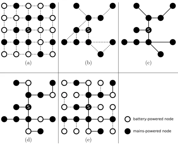
network consists of 500 sensor nodes, 100 of which, including the sink, are mains-powered. The nodes are distributed to a square-shaped area with an edge length of 10 units. Communication range of each node is 1 unit. The sink is located at the center of the area. In the figures, the battery-powered nodes are de-noted by small circles and the mains-powered nodes are shown as larger circles. Figure 3.1 (a) shows the visibility graph of the network; if a node is in the com-munication range of another, there is an edge between the vertices representing these two nodes. We assume links are symmetric. Given such a visibility graph, our approach can extract a backbone similar to the one shown in Figure 3.1 (c). Connectivity information of the mains-powered nodes, reduced to a spanning tree as in Figure 3.1 (b), is used to form the backbone, which is explained later in this section. Please note that all mains-powered nodes take part in the backbone, and in some cases battery-powered nodes are used to interconnect them. Finally, Figure 3.1 (d) shows the routing tree formed as the rest of the nodes connect to the backbone.
The proposed approach can be described in a more formal manner by the following three-step procedure:
1. Reduce the visibility graph G = (V, E) to a secondary graph G0 = (V0, E0) such that
(a) V0 ← {v ∈ V | v is mains-powered},
(b) ∀ vi, vj ∈ V0, the edge (vi, vj) ∈ E0 ⇐⇒ (vi, vj) ∈ E or ∃ a simple
path p = (v1, v2, ..., vn) between vi and vj in G s.t. v1, v2, ..., vn are all
battery-powered and |p| < T , and then
(c) assign a cost value to each edge e0 ∈ E0.
2. Extract a backbone:
(a) Find a spanning tree on G0,
(b) Map the spanning tree on G0 to a tree on G.
(a) (b)
(c) (d)
Figure 3.1: (a) Visibility graph, (b) a spanning tree on the mains-powered node connectivity graph, (c) backbone, and (d) routing tree graph (reprinted from Fig. 1 of [1] c 2010 IEEE).
This procedure is actually a framework for a class of algorithms rather than a complete description of a single algorithm because there are several alterna-tives for some of its steps. Let us explain the procedure step by step with the alternatives where necessary.
In Step 1, the original network visibility graph is reduced to a secondary graph in which the vertices are the mains-powered nodes (Step 1-a) and the edges represent the connectivity of these nodes. Two mains-powered nodes are assumed to be connected either if they are in direct communication range of each other or if there is a simple path between them shorter than or equal to a threshold T and consisting of only battery-powered nodes (Step 1-b).
In Step 1-c, cost values are assigned to the edges of the secondary graph to be used in Step 2 of the procedure. Two alternatives are considered for this step, given two vertices representing the mains-powered nodes, and an edge between them: 1) Minimum number of battery-powered nodes between the two mains-powered nodes and 2) A value inversely proportional to the number of vertex disjoint paths (shorter than or equal to a threshold, T , and consisting of only battery-powered nodes) between the two mains-powered nodes. The first method is expected to reduce the amount of energy consumed by the battery-powered nodes, whereas the second method is considered for fault tolerance, that is, if one of the paths between the mains-powered nodes becomes unusable due to a node failure, another path can be chosen from the alternatives. Instead, the alternative paths between the mains-powered nodes can also be used for load balancing by sending each packet through a different alternative path.
In Step 2 of the procedure, the backbone is formed. First a spanning tree on the secondary graph is found (Step 2-a), similar to the one in Figure 3.1 (b). This spanning tree is used as the basis of the backbone on the actual network. A minimum spanning tree (MST) and shortest path tree (SPT) rooted at the sink are considered as alternatives. Although an MST is expected to give better network-wide results than an SPT, especially when data is aggregated, the lat-ter has a less-complex distributed implementation. The backbone is yielded by mapping the spanning tree on the secondary graph back to a tree on the original
graph (Step 2-b), which corresponds to mapping each edge of the spanning tree on the secondary graph to a path on the original graph. End points of the paths are the vertices representing mains-powered nodes and nodes on the paths are the battery-powered nodes connecting the corresponding mains-powered nodes. In the algorithms given in Section 3.2, the paths are chosen to be the shortest simple paths connecting mains-powered nodes and there might be no battery-powered nodes on the paths if mains-battery-powered nodes are immediate neighbors. The mapping can be seen in Figure 3.1 (b) and (c). After these first two steps, the backbone is formed.
Finally, in the last step of the procedure, the remaining battery-powered nodes, i.e., the nodes are not connected to the backbone yet, are connected to the nodes that are part of the backbone (Step 3), either directly or over multiple-hops. Although there might be other alternatives, in the algorithms presented in Section 3.2, mains-powered nodes are chosen to have precedence over battery-powered nodes to be parents of the connecting nodes. The final routing tree is similar to the one in Figure 3.1 (d).
So far the algorithm framework and properties of possible concrete algorithms are described but their implementations are not explained. Centralized implemen-tation is one of the alternatives. In the centralized implemenimplemen-tation, each node sends its neighbor list to the sink and in this way the sink obtains the complete network topology information. The sink then executes the centralized algorithm and sends back the final connectivity information to the nodes according to the algorithm results. Whenever neighborhood information of a node changes, the sink is informed about the situation and the topology is restructured according to the current visibility of the nodes, if required. More detail on centralized implementation is provided in Section 3.2.
Distributed implementation is another alternative. Although both MST and SPT have distributed implementations available in the literature [87][88], finding an MST of a graph in a distributed manner is more complex than finding an SPT. In a distributed implementation of SPT case, local information, which includes neighboring mains-powered nodes (other mains-powered nodes connected directly
or through a limited number of battery-powered nodes) and the path alternatives to them, can be collected at mains-powered nodes. Hence each mains-powered node can have a partial view of the visibility graph. In order to construct an SPT, distance to the sink can be shared between connected mains-powered nodes. Once a mains-powered node determines its parent, which has the minimum distance to the sink among its mains-powered neighbors, it may also decide the path to its parent among the alternatives. This corresponds to a partial mapping of the secondary graph to the original graph handling part of the step 2-b of the procedure. Nodes that are not declared as part of the backbone by the mains-powered nodes can be connected to the backbone as in the last step of the procedure. More detail on distributed implementation is provided in Chapter 4.
3.2
Sample Centralized Algorithms Based on
Our Framework
In this chapter, we mainly focus on the centralized implementation of the algo-rithms based on our proposed framework. Before going into the details of the centralized algorithms, let us first clarify some of the terms that we use in the algorithm descriptions. Two nodes are neighbors if they are within communica-tion range. The peer of a mains-powered node is another mains-powered node (possibly the sink) that is reachable through less than T battery-powered nodes, where T > 0. Battery- and mains-powered nodes send their data to their parents in the data gathering process. The parent of a mains-powered node is one of its peers, whereas the parent of a battery-powered node is one of its neighbors.
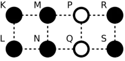
K M L N P Q R S
Figure 3.2: A portion of a sample wireless sensor network.
ring-shaped vertices denote battery-powered nodes, solid-circle-shaped vertices denote the mains-powered nodes, and the edges denote the wireless links between the nodes. In the sample network, neighbors of node M are K, N , and P . Assuming the threshold T is 2, peers of M are K, N , and R: K and N are immediate neighbors of M and there is a path between R and M whose length is less than or equal to T (i.e., 2) and consisting of only battery-powered nodes. M and S are not peers since shortest path between these two nodes consisting of only battery-powered nodes is 3, which is greater than T . Similarly M and L are not peers: although they are 2 hops away, there is no path between them consisting of only battery-powered nodes. Assuming the sink is S and M sends its data to the sink through P and R, parent of M is R.
Based on our algorithm framework, we propose four different algorithms that aim at constructing a backbone structure to route the data traffic through, as listed below.
1. Algorithm “# of BP-Nodes + MST”,
2. Algorithm “# of Disjoint Paths + MST”,
3. Algorithm “# of BP-Nodes + SPT”,
4. Algorithm “# of Disjoint Paths + SPT”.
The first two algorithms construct the spanning tree over the secondary graph as a minimum spanning tree (MST) and the latter two algorithms construct the spanning tree as a shortest path tree (SPT). Furthermore, the first and the third algorithms use the minimum number of battery-powered nodes connecting peers (i.e., mains-powered node pairs) as the edge costs on the secondary graph, and the second and the fourth algorithms make use of a value inversely proportional with the number of vertex disjoint paths connecting peers to assign costs to edges. More algorithms can be derived from our algorithm framework by considering different cost functions or different tree formation algorithms. We propose and analyze these four specific algorithms in this chapter.
Algorithm 3.1 Construct the backbone
functionConstructBackbone(G(V, E),ps)
1: {find peers and all possible paths between them} 2: paths ← FindPeers(G(V, E),ps)
3: {reduce GtoG0 and compute the edge costs ofG0} 4: G0(V0, E0, cost) ←ReduceGraph(G(V, E),ps,paths)
5: {given G0 and cost, find a spanning tree, that is G00} 6: G00(V00, E00) ←FindMST(G0, cost)
7: {mapG00 back to a tree on Gto obtain G( ¯¯ V , ¯E)} 8: for all edge(u, v) ∈ E00 do
9: V ← ¯¯ V ∪ u ∪ v
10: path ← argminl(|l|, ∀ l ∈ pathsuv)
11: last ← u
12: for allnode non path l do 13: V ← ¯¯ V ∪ n 14: E ← ¯¯ E ∪ (last, n) 15: last ← n 16: end for 17: E ← ¯¯ E ∪ (last, v) 18: end for 19: return G( ¯¯ V , ¯E)
In Algorithms 3.1, 3.2, and 3.3, we give the pseudocodes for the centralized implementation of one of our four algorithms, the “# of BP-Nodes + MST” algorithm. The pseudocodes assume that the visibility graph G(V, E) of the network and the power-source types of the nodes ps are already available at the sink. Note that, these pseudocodes can easily be modified to implement the other algorithms, besides “# of BP-Nodes + MST” algorithm.
In Algorithm 3.1, which constructs the routing backbone, first peers (mains-powered nodes) and possible paths between them are computed. The details of this step are given in Algorithm 3.2. In the algorithms, paths is a data structure such that pathsuv stores the list of all possible paths between mains-powered nodes u and v, and each path between u and v is a sequence of battery-powered nodes, excluding the mains-powered end points (i.e., u and v). In Algorithm 3.2, a queue of node sequences (i.e., paths), Q, is used to explore all possible paths between the mains-powered nodes. For each mains-powered node m, first a sequence containing only the mains-powered node itself is pushed to the queue Q. Then,
until Q is empty, sequences are popped and according to the power-source types of each newly explored node, either a new path is discovered to a mains-powered node and added to paths (line 11) or a new sequence is obtained (by adding the new node to the current sequence) and pushed to the queue (line 8).
Algorithm 3.2 Find peers and paths between them
functionFindPeers(G(V, E),ps)
1: for all mains-powered nodem ∈ V do 2: push(Q, [m])
3: while Q 6= ∅ do 4: L ←pop(Q)
5: for all v adjacent to front(L)inG do 6: if psv=battery-powered then 7: if (|L| < T ) ∧ (v /∈ L) then 8: push(Q, L + v) 9: end if 10: else if v 6= m then 11: pathsm v ← pathsmv ∪ (L − m) 12: end if 13: end for 14: end while 15: end for 16: return paths
Next in Algorithm 3.1, the original visibility graph is reduced to a secondary graph, whose details are given in Algorithm 3.3. In Algorithm 3.3, vertices are added to the secondary graph for all mains-powered nodes (line 3), and edges are added for all mains-powered node pairs if there is path between them stored in paths (line 7). For each edge added, a cost value is also computed. Here, the length of the shortest path between the nodes in the original graph is chosen as the cost metric (line 8), but other alternatives can easily be adapted.
Then, in Algorithm 3.1, a spanning tree on the secondary graph is computed using the minimum spanning tree algorithm (line 6, details are not provided). Note that, here the minimum spanning tree algorithm can be replaced by a span-ning tree algorithm of choice. In the last part of Algorithm 3.1 (lines 8-18), the spanning tree on the secondary graph G0, that is G00, is mapped back to a tree on the original graph G, and therefore the backbone, ¯G, is obtained. While
Algorithm 3.3 Reduce graph
functionReduceGraph(G(V, E),ps,paths)
1: for all u ∈ V do 2: if psu=mains-poweredthen 3: V0← V0∪ u 4: for all v ∈ V do 5: if psv=mains-powered then 6: if pathsu v 6= ∅ then 7: E0 ← E0∪ (u, v)
8: cost(u,v)← |argminl(|l|, ∀ l ∈ pathsuv)|
9: end if 10: end if 11: end for 12: end if 13: end for 14: return G0(V0, E0, cost)
mapping the edges of G00 to the paths on G, shortest possible paths between the mains-powered nodes are chosen (line 10). Note that the mains-powered nodes (line 9) are added to the backbone as well as the battery-powered nodes (line 13) connecting these mains-powered nodes.
3.3
Evaluation of the Proposed Approach
In order to evaluate the effectiveness and the performance of our approach and its alternative algorithms obtained by selecting different sub-algorithms and cost functions, described in Sections 3.1 and 3.2, we implemented a custom simulator in C++ and run a set of simulation experiments. In our simulations, our power-source-aware backbone-based routing approach is compared with a basic shortest path tree routing algorithm, in which battery- and mains-powered nodes are not distinguished and each node is connected to the sink via the shortest possible path. For our backbone-based routing approach, either the minimum number of battery-powered nodes or 1/d, where d is the number of vertex-disjoint paths bounded by a threshold T , is chosen to be the cost value assigned to the edges

![Figure 3.6: Mains-powered node ratio vs. network lifetime (reprinted from Fig. 5 of [1] c
2010 IEEE).](https://thumb-eu.123doks.com/thumbv2/9libnet/5956384.124379/52.918.213.746.179.497/figure-mains-powered-ratio-network-lifetime-reprinted-ieee.webp)