TUESDAY AFTERNOON
/ CLlO
2001
/
603
.
JTuD6 6:OO pmExperimental demonstration of highly conflned photonic crystal based waveguides
Mehmet Bayindir and E. Ozbay,
Department of Physics, Bilkent University, Bilkent, 06533 Ankara, Turkey
B. Temelkuran, Department of Material Science
and Engineering, Massachusetts Institute of Technology, Cambridge, MA 02139
M.M. Sigalas, Communications and Optics Lab, Agilent Labs, Agilent Technologies, 3500 Deer Creek Road, MS26M9C, Palo Alto, CA 94304
C.M. Soukoulis, R. Biswas, and K.M. Ho,
Ames Laboratory and Microelectronics Research Center, Iowa State University, Ames, IA 5001 I ;
Email: bayindir@fen. bilkent.edu. tr
There is great deal of interest in developing pho- tonic crystal based waveguides where one can confine and efficiently guide the light around sharp corners.'" Guiding the light without losses, and even through sharp corners was ob- served in two-dimensional (2D) photonic crys- tals.' However, to avoid the leakage problem in 2D structures, either one has to extend the size of the photonic crystal in the vertical direction, or use a strong index-guiding mechanism in the ver- tical direction: A way to eliminate the leakage is to use a three-dimensional (3D) photonic crystal. Here, we demonstrate the guiding and bending of EM waves in highly confined waveguides which were constructed by removing a single rod from a perfect 3D layer-by-layer photonic crystal.'
In our experiments, we used a layer-by-layer dielectric photonic crystal based on square shaped alumina rods (0.32cm x 0.32cm x 15.25cm), with center-to-center separation of 1.12 cm. The crystal exhibits a three-dimensional photonic band gap with a mid-gap frequency around 12 GHz. Figure 1 shows the schematics of the measurement setup that was used in our ex- periments. We used an HP 8510C network ana-
+
lyzer and microwave horn antennas to measure the transmission-amplitude properties of a straight waveguide (upper panel in Fig. 1) and a 90-degree bended waveguide (lower panel in Fig. 1). The polarization vector e of the incident EM wave was kept parallel to the stacking direction of the layers.
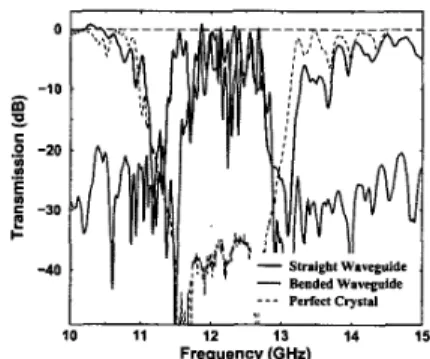
-First, we investigated the guiding of EM waves by measuring the transmission through a straight waveguide which was constructed by removing a single rod from a single layer of a 6 unit cell (24 layer) photonic crystal, so that we have 12 layers at the top and 11 layers at the bottom of the re- moved rod. As shown in Fig. 2 (solid line), we ob- served full transmission of the EM waves for a certain frequency range, within the stop band. The full transmission throughout the waveguid- ing band was a proof of how well the wave was confined and guided without loss.
Then, we tested the bending of light through
sharp corners in this waveguide structure, we re- moved part of a single rod from I l t h layer, and part of another rod from 12'h (adjacent) layer as shown in Fig. 1 (lower panel). The resulting va- cancies of the missing parts of rods forms a 90- degree sharp bend waveguide. The incident wave, propagates along the first waveguide (missing portion of the rod on the 1 lth layer), and success- fully couples to the second waveguide on the 12th layer, which is perpendicular to the propagation direction of the incident EM wave. As shown in Fig. 2 (dotted line), we observed a waveguiding band, for which the frequency range of the band was similar to the straight single rod removed waveguide. The high transmission-amplitudes reaching unity around certain frequencies showed that the EM waves were coupled and guided through the waveguide that contained a sharp bend. In Fig. 2, we also plotted the trans- mission spectra (dashed line) of the perfect crys- tal as a comparison. The guiding is limited with the stop band of the photonic crystal, for which the crystal has the property of reflecting the EM waves in all directions.
At this point, we would like t o compare our bended waveguide results with the simulations previously reported for this structure by Chuti- nan and Noda.' Based on their simulation, the waveguiding band for sharp bend structure cov- ers 67% of stop band of the photonic crystal
JTuD6 Fig. 1. Experimental setup for meas- uring the transmission spectra of a straight (upper panel) and bended (lower panel) wave- guides. The straight waveguide was created by re- moving a single rod from one layer while the 90- degrees bended waveguide obtained by removing two rods partially from two adjacent layers.
10 11 12 13 14 15
Frequency (GHr)
JTuD6 Fig. 2. Transmission spectra measured from a straight (solid line), a 90-degree bended waveguides (dotted line), and the perfect crystal. Nearly a 100% transmissions were obtained for certain frequencies throughout the guiding band.
which is very close to the our experimentally re- ported value 68%.
In order to understand the underlying physics behind these single rod removed waveguides, we need to closely look at the structure of the wave- guide. Each vacancy just below the removed rod behaves as a cavity, and the coupling between these localized cavity modes allow propagation of photons by hopping through the vacancy of the missing rod! The experimental results, disper- sion relation and photon lifetime, agree well with the tight-binding analy~is.~
In conclusion, we have experimentally demon- strated that a fully confined waveguide can be con- structed by removing a single rod in a layer-by- layer photonic crystal. Full transmission of the EM waves was obtained through a straight wave- guide and a waveguide with a sharp bend con- structed by removing rods. These results encour- age the usage of the layer-by-layer photonic
crystal structure in the design of future ultra- small optoelectronic integrated circuits?
F
=,,
sz
5
P' L't
References E*:*1. A. Mekis et al., Phys. Rev. Lett. 77, 3787 (1996); Shawn-Yu Lin, E. Chow, V. Hietala, P.R. Villeneuve, and J.D. Joannopoulos, Sci- ence 282,274 (1998).
M.M. Sigalas etal., Micro. Opt. Tech. Lett. 23, 56 (1999).
A. Chutinan and S. Noda, Appl. Phys. Lett. 75,3739 (1999).
M. Bayindir, B. Temelkuran, and E. Ozbay, Phys. Rev. Lett. 84,2140 (2000); M. Bayindir,
B. Temelkuran, and E. Ozbay, Phys. Rev. B 61, R11855 (2000).
S . Noda, K. Tomoda, N. Yamamoto, and A. Chutinan, Science 289,604 (2000). S.G. Johnson, P.R. Villeneuve, S. Fan, and J.D. Joannopoulos, Phys. Rev. B 62,8212 (2000). M. Bayindir, B. Temelkuran, E. Ozbay, M.M. Sigalas, and C.M. Soukoulis, R. Biswas, and K.M. Ho, Submitted to Phys. Rev. Lett. (Oc- tober 2000). 2. 3. 4. 5. 6. 7. JTuD7 6:15 pm
Nondegenerate monopole mode of the single-defect two-dimensional triangular photonic band gap cavity
loon Huh, Jeong-Ki Hwang, Hong-Kyu Park, Han-You1 Ryu, and Yong-Hee Lee, Department
ofphysics, Korea Advanced Institute of Science and Technology, Taejon 305-701, Korea; Email: huhjoon@. kaist.ac. kr
The use of a single-defect photonic band gap (PBG) cavity offers the possibility of spontaneous emission modification' and nearly thresholdless laser operation.' Recently, Caltech group demon- strated a single-defect PBG laser based on a dipole defect mode of two-dimensional (2D) triangular lattice? In this work, we propose and characterize a nondegenerate 2D monopole mode instead of
the degenerate dipole mode as a candidate for a thresholdess PBG laser.
The FDTD(finite-difference time-domain method) with PML(perfect1y matched layer) boundary condition is used for the analysis of de- fect modes of 2D PBG cavity. The single-defect 2D triangular cavity structure used in our study has air-hole radius of 0.35 a and effective refrac- tive index of 2.65; while the radius and position