RESEARCH ARTICLE - COMPUTER ENGINEERING AND COMPUTER SCIENCE
Embedded Fuzzy Logic Control System for Refrigerated Display
Cabinets
Kemal Tutuncu1 · Recai Ozcan2
Received: 8 December 2018 / Accepted: 16 April 2019 / Published online: 11 May 2019 © King Fahd University of Petroleum & Minerals 2019
Abstract
Having done in this study, embedded fuzzy logic control system (EFLCS) was designed and implemented for closed refrig-erated display cabinets (CRDC) to meet the required storage conditions for the pastry productions stored in CRDCs. The
system keeps the temperature and relative humidity (RH) of CRDC at approximately+ 4◦C and 80% RH, respectively. It
has two fuzzy logic controllers. One of them controls the speed levels of the fans, and the other controls the steam level of ultrasonic atomizer. Temperature and RH values are read by sensor SHT11 and transferred to PIC18F4620 microcontroller that is programmed with fuzzy Logic approach. On the other hand, the compressor was controlled with on–off control in the
range of 3–5◦C. On the condition of starting from+ 7◦C temperature, the time to approach to the set values (4◦C and 80%
RH) for traditional system and EFLCS is 191.8 and 109.6 s, respectively. Additionally, the ranges of temperature and RH
obtained by EFLCS are between 4.44 and 3.69◦C and between 81.33% RH and 78.57% RH, respectively. The temperature and
RH values obtained by traditional system are between 5.56 and 3.2◦C and between 61.81% RH and 57.45% RH, respectively.
Traditional system never reached to desired humidity value (80% RH). It has been seen that developed EFLCS becomes stable in shorter time than traditional system and kept the desired values as almost constants.
Keywords Fuzzy logic control· Embedded system · Refrigerated display cabinet · PWM · SHT11
1 Introduction
Refrigerated display cabinets (RDCs) are great and vital as
they are part of the cold chain for food products [1]. It is easier
to reach the desired weather conditions in CRDCs compared
to open RDC (ORDC) [2]. Particularly the temperature and
humidity are the conditions that should be provided in the pastry products.
After making the pastry products, it may be necessary to display a certain period of time in the store for sale, if this time is too long and the necessary storage conditions for the product are not provided, the pastry products may deteriorate or loss mass. The ideal conditions are adversely affected due to the not achievable ideal relative humidity range, the temperature fluctuations and the door of cabinet
B
Kemal Tutuncu [email protected]1 Department of Electric Electronics Engineering, Selcuk
University Technology Faculty, 42130 Konya, Turkey
2 Department of Electric and Energy, Selcuk University Bozkir
Vocational School, 42630 Konya, Turkey
which is often opened for product sales. Therefore, the shelf life of products in CRDC is shortened.
For refrigerated foods, generally between− 1 and + 5◦C
is the acceptable temperature range [3]. Therefore, the
tem-perature and the humidity of the environment where the cake will be hold must be kept at a certain value. Ideal
temper-ature and humidity can be considered as + 4◦C and 80%
RH, respectively, in order to prevent growing pathogenic
microorganisms. Figure 1 shows how pathogenic bacteria
grows according to the temperature change.
During the product display in RDCs, moisture loss or gain will continue to occur until the environment and food com-ponents (cream and etc.) that surround the food reach the
thermodynamic balance [5]. Due to dehydration, the
appear-ances of unwrapped foods are deteriorated and limit the shelf life. Consumers are preferred newly loaded products com-pared to the product that have been displayed for some time
[6]. Furthermore, the evaporation of water from the product
is the mass loss of the salable product. In a survey conducted, attention was focused to the importance of relative humidity. Relative humidity decreased from 95 to 40% caused
Fig. 1 Bacterial growth rate for human pathogens at different
temper-atures [4]
process have a positive effect on the microbial quality of the products, but also extends the shelf life. Using humidification equipment to increase the humidity of the cabinet in which the product is stored is a way of reducing the problems
men-tioned [8].
Consumers prefer indoor CRDCs because of pastry prod-ucts in Turkey usually displayed as unpacked. Traditional CRDCs which are produced in Turkey have generally only on–off temperature control. There is no humidity control, and humidity is supplied by fans that are directed to the water at the bottom of CRDC. The humidity value is at most 65% RH, and the ideal humidity value (80% RH) is not reached. The basic motivation of this study is to reach the ideal humidity and temperature values in shorter time than traditional sys-tem and to preserve these values. In this way, it is ensured that the shelf life of the cakes is longer than it was before.
Microbiological safety of chilled foods is the main key fac-tor and requires product design and cold chain management. Many technology areas are used to make safe products and
ensure shelf life [9]. In recent years, computer and
communi-cation technology has seen great progress based on real-time status information on cold stores and RDC. RDCs can have integrated temperature and humidity control to extend the shelf life of non-pre-packaged foods. Thus, the measurement and control of food environment conditions can be part of the
safety and quality system [10]. Embedded systems are
com-puter systems designed for a specific purpose. These systems
include not only hardware, but also embedded software [11].
Thanks to this embedded software and hardware, CRDC can be controlled depending on the critical values of temperature and humidity.
In this study, an EFLCS that can easily be mounted to compatible current CRDCs without too many changes was designed and implemented. Developed EFLCS simul-taneously receives information from different sensors and simultaneously activates different actuators. Contribution to the development of alternative solutions to meet the current requirements for CRDCs such as desired RH and temperature values was aimed.
There are some studies in the literature related to control system for ORDC in various countries that are out of scope of
this study [12–18]. Because, ORDCs do not have doors and
use different techniques such as air curtain and air guiding strip, to replace the doors and to provide the air condition-ing. The parameters to be controlled are different from the parameters of CRDC. Additionally, there are not many stud-ies conducted with control system for CRDC that are similar to developed EFLCS in this study. Experimental and numer-ical control studies for CRDC in recent years are shown in
Tables1and2, respectively [19–38]. When both tables are
examined, it has been seen that the methods used for control-ling aims are FLC, mode control, PID control, fuzzy expert system, On–off control and sliding mode control. Addition-ally, the controlled parameters are mainly temperature and
humidity [19–38]. Only several studies [24,29,35,37] have
one additional control parameter. At this point, it should be declared that there is no benchmark to compare CRDC
stud-ies [19–38] to each other since different sizes of areas (from
an incubator to big cold storage) and zones (food storage, health, livestock and etc.) were air-conditioned. It means that CRDC studies are domain-specific ones and there is no way of comparing the time for reaching target values, the sta-bilities, etc. with previously developed systems or studies.
Thus, the authors of these papers [19–38] only compared
their methods with traditional systems applied on their areas. Due to these reasons, developed EFLCS was compared with traditional system that exists on CRDC used in this study.
2 Material and Method
The embedded system can be defined as microcontroller /microprocessor-based system designed to control a func-tion or funcfunc-tion range. The embedded system includes: a processor capable of performing the required tasks within the system, a memory that stores the software and the data generated during the operation, peripheral units for commu-nicating with the outside world, a software for efficiently running the system, an algorithm which has the ability to interpret the sensors data and generate the control signal
according to this data [39]. In general, an embedded
sys-tem is implemented by: (1) circuit design and simulation, (2) experimental demonstration of the designed circuit (on a breadboard), (3) application of the circuit (soldering), (4)
packaging [40].
Microcontroller needs to be programmed to operate according to certain parameters. FL, which can incorporate human thinking ability and experience into the control sys-tem, promises both to fix the system in a shorter time and to provide oscillation at lower intervals. FL is also a popular tool that provides decision support for analyzing data classes
Table 1 Similar experimental studies in recent y ears Air -conditioned zone Method Ev aluation factors T ar g et v alues Control factors Y ear References Oyster mushroom culti v ation F uzzy logic control T emperature Between 15 and 3 0 ◦C R elay 2018 [ 19 ] Humidity Between 80 and 9 0% Sprayer Closed house chick en barn Fuzzy logic control T emperature Between 26 and 2 9 ◦CE x h au st fa n 2 0 1 8 [ 20 ] Humidity Between 50 and 7 0% Inf ant incubator M ode control T emperature Between 27 and 3 7 ◦C F an 2018 [ 21 ] Suction Alarm RT C Agricultural g reen house + MA TLAB simulation Comparison of fuzzy logic self-tunning and P ID T emperature 30 ◦C P iezoelectric-transducer 2017 [ 22 ] Humidity 60% Heater Air conditioning system + M A TLAB simulation Comparison of real system and M A TLAB simulation T emperature (29–30–35–43–47) ◦C C ompressor 2017 [ 23 ] Humidity (32–24)% Cold storage F uzzy logic control T emperature 4, 5 ◦C F ans 2 017 [ 24 ] Humidity 92,50% Humidifier Light intensity 12,50% Dehumidifier Luminance controller Greenhouse F uzzy logic control T emperature User defined Electric pump 2017 [ 25 ] Humidity User defined
Humidifier Heater Lighting Extractor
Fungus culti v ation F uzzy logic control T emperature Between 20 and 2 8 ◦C R elay 2015 [ 26 ] Humidity Between 80 and 9 0% Electric pump Lamp Maintenance comfortable room Mode control T emperature Between 18 and 3 4 ◦CL am p 2 0 1 6[ 27 ] Humidity Between 40 and 7 0% F an Electric pump Exhaust fan Inf ant incubator P ID control T emperature User defined Heater 2015 [ 28 ] Humidity User defined Alarm Poultry house C omparison o f fuzzy logic and on–of f control T emperature 23 ◦C H eater 2014 [ 29 ] Humidity 60% F an C ooler CO 2 3000 ppm Humidifier NH 3 25 ppm
Table 2 Similar numerical studies in recent y ears Air -conditioned zone Method Ev aluation factors C ontrol factors Y ear References V ariable speed direct expansion air conditioning system Fuzzy logic control T emperature Compressor 2018 [ 30 ] Humidity V ariable speed refrigeration system Comparison of fuzzy logic control and simulation T emperature C ompressor 2018 [ 31 ] T emperature control o n L ABVIEW PID control T emperature Heater 2017 [ 32 ] T est temperature ˙ Indoor air temperature and humidity W eights b ased fuzzy logic control ˙ Indoor temperature F an 2017 [ 33 ] ˙ Indoor humidity C ompressor Automoti v e refrigeration system Comparison of on–of f control and sliding m ode control T emperature C ompressor 2017 [ 34 ] Ambient temperature Ev aporator fa n-VFD frequenc y Heating load C ondenser fa n-VFD frequenc y Air conditioning system on MA TLAB fuzzy toolbox Fuzzy logic control T emperature F an 2016 [ 35 ] Humidity Compressor Oxygen le v el Fin d irection Operation (A C or dehumidifier) ˙ Indoor temperature C omparison o f thermostats control and fuzzy logic control ˙ Indoor temperature H eating system 2016 [ 36 ] Outdoor temperature A ir conditioning system Outdoor humidity HV A C system with LABV ˙ IEW and M A TLAB simulink Fuzzy expert system ˙ Indoor temperature H eat v alv e 2015 [ 37 ] ˙ Indoor humidity C old v alv e ˙ Indoor oxygen E xhaust m otor Outdoor temperature W ater pump Centralized chilled w ater system on MA TLAB simulink Fuzzy logic control T emperature Damper position 2014 [ 38 ]
Fig. 2 General scheme of design
Developed EFLC system is aimed for keeping tempera-ture and humidity inside a CRDC manufactempera-tured in Turkey
at approximately+ 4◦C and 80% RH, respectively. Input
variables are temperature and humidity information, whereas output variables are speed levels of fans (3) and the steam level of UA. The temperature is provided by evaporative cooling, and the humidity is supplied by UA as cold steam. The fans that are placed near the evaporator are used to reach the desired level of CRDC temperature easily. The temperature and humidity information is transferred by the SHT11 sensor to the PIC18F4620 that is programmed with FL approach. Symmetric fuzzification, Mamdani inference mechanism and weight average method for defuzzification are used for programming PIC18F4620. Depending on these transferred values, the fans and UA are operated to pro-vide the necessary air conditioning for the cake. The gas
compressor is on–off controlled in the range of 3–5◦C to
keep the inside temperature of CRDC at 4◦C by relay
G5LE-1-ACD model of OMRON company. In addition, the values of all input and output variables can be monitored instantaneously through the interface screen. The scheme of
developed EFLCS is shown in Fig.2.
2.1 Control Card with Microcontroller
Microchip’s PIC18F4620 40-pin microcontroller unit (MCU) has 64K flash, 1K EEPROM, Capture/Compare /PWM modules and built-in USART support. It also has a
10-bit analog-to-digital converter module. This module has 13 inputs and provides conversion of an analog input signal to a corresponding 10-bit digital number. The PIC18F4620 is operated in three modes. These modes are Normal, Idle and Sleep.
The PIC18F4620 microcontroller is selected to develop EFLCS because it has built-in USART support, many digi-tal outputs, 64 kB program memory and different operating modes.
The input/output ports on the control card enables PIC microcontroller to communicate with peripheral devices and the computer. The data cables from the sensors are connected to the input ports of the control card, the fans and UA and the relay pins are connected to the output ports. The control card also has a COM port. The control card can be connected to the computer via this port. Thus, the interface program on the computer can display and record the input/output data. This function has no effect on the operation of EFLCS. FL-based software on the PIC18F4620 evaluates the information from the sensors and sends the control signals to the fans, relay and UA via this card for the purpose of making the air conditioning of CRDC. Therefore, the control card has the most important function in developed EFLCS.
2.2 Sensors
The SHT11 sensor measures temperature and humidity values simultaneously in an environment. For developed
EFLCS, eight expansion slots were integrated to control card to make connection with SHT11 sensors. Since the measure-ments of temperature and humidity in five different regions of CRDC (lower left, lower right, upper left, upper right and near evaporator) were needed, only five of the expansion slots were used to connect five pins of SHT11 sensors. Fifth sen-sor on the evaporator was used to increase the efficiency of evaporator by minimizing the snow on the evaporator surface. For efficient air conditioning system, the difference between the average temperature of the cooled area and tempera-ture of cooler liquid inside the evaporator must not exceed
5◦C. In case of having the temperature difference more than
5◦C, the water steam starts condensing. This causes snow on the evaporator and decrease in relative humidity ratio of the cooled area. To eliminate this situation and to keep this
temperature difference under 5◦C, air circulation must be
provided between the evaporator and cooled area. Figure3
shows SHT11 connection schema.
SHT11 measures and sends these data in digital form to microcontroller since it has built-in analog-to-digital converter (ADC). SHT11 uses a bidirectional (two-wire) interface for data communication with microcontroller.
Fig. 3 SHT11 connection circuit [42]
2.3 Driver and Fans
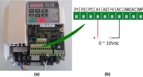
The frequency converter arranges the output voltage for the fans used in this study according to the analog signals com-ing from the control card. In developed EFLCS, YASKAWA V1000 model inverter/driver was used as frequency converter to drive the fans. This driver features 1.5 kW, single phase,
220-V 50 Hz input and 200-V output. Figure4a shows the
YASKAWA V1000 inverter/driver, and Fig. 4b shows the
control inputs.
YASKAWA V1000 inverter/driver’s pulse width modula-tion (PWM) is V/f (voltage/frequency) -controlled, and the output frequency is between 0 and 400 Hz. The output voltage waveform has a constant amplitude. Variable output volt-age is obtained by switching the source voltvolt-age at regular intervals. The output voltage is determined by adjusting the amplitude of the signal in each cycle. The fans were driven by this output voltage. Each fan used in developed EFLCS is
120 cm× 120 cm × 38 cm and operates with 0–220 V AC.
Figure5shows one of the fans driven by the driver used in
the design.
The frequency converter receives the control signal from the control card of developed EFLCS in the range of 0–10
Fig. 5 The fan
Fig. 4 a YASKAWA V1000
model inverter/driver and b YASKAWA V1000 control inputs [43]
Fig. 6 PWM signals with different duty cycles and sample switching
circuit [44]
Fig. 7 Control signal for PWM level 50
Vdc. The values of voltage, current and frequency that cor-respond to control signal value are produced as outputs and also can be monitored via this device. In this way, precautions can be taken against undesirable situations that may occur in the system.
2.3.1 Obtaining PWM Control Signal
PWM is a way of obtaining energy by consecutive pulses instead of a continuously changing (analog) signal. This pulse width is increased or decreased to regulate the energy
flow. Figure6shows PWM signals with different duty cycles
and sample switching circuit.
The control signal 0–10 Vdc required to control the driver was controlled by adjusting the pulse width of the voltage from 10 Vdc source. This adjustment or setting is imple-mented by triggering the IRF52N MOSFET through 0–5 Vdc output of microcontroller.
The PWM range of microcontroller is set to be between 0 and 255. In developed EFLCS, the input read by the sensors is evaluated by the program that makes use of FL approach and is loaded to microcontroller. Thus, the sharp values are obtained. These sharp values are assigned to the task period of the PWM signal to be generated by the PIC18F4620. This task period with a start value of zero is reassigned as soon as the sensors are read. Two examples are given below:
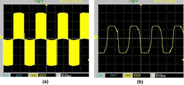
For PWM level 50 The oscilloscope output of the control
signal for PWM level 50 is shown in Fig.7.
The oscilloscope image of the driver’s output signal
cor-responding to this signal (PWM level 50) is shown in Fig.8a,
and the oscilloscope image of the average of the driver’s
out-put signal is shown in Fig.8b.
Fig. 9 Control signal for PWM level 200
For PWM level 200 The oscilloscope output of the control
signal for PWM level 200 is shown in Fig.9.
The oscilloscope image of the driver’s output signal
corre-sponding to this signal (PWM level 200) is shown in Fig.10a,
and the oscilloscope image of the average of the driver’s
out-put signal is shown in Fig.10b.
2.4 Humidifier
The device that performs the cold humidification process is called UA. UA produces cold mist at approximately fre-quency range 1–2 MHz. The main material of UA is the asymmetric quartz crystals which, when the required fre-quency value is reached, cause mechanical vibrations to
occur. After the main voltage is reduced by a transformer, it is converted to a 1.65 MHz frequency signal by an electronic circuit. This signal is transferred to a transducer mounted in a water reservoir. The transducer converts this signal to high frequency vibration. With the effect of the 1.65 MHz fre-quency signal, it changes its thickness by 1.65 million times a second. As a consequence of the high frequency vibration of the transducer surface and the momentum of the water due to the inertia of the water, this vibration of the water can-not keep up with it, which causes the water column to form in the transducer. During the transducer is shrinking in the negative direction, the water cannot follow this rapid move-ment and instantaneous vacuum occurs in the region above the transducer. Due to the vacuum, cavitation starts on the surface of the water and causes water particles to form under low temperature and pressure. During the positive expansion of the transducer, the water particles move rapidly toward the surface of the water column and collide with each other at high velocities. At the wave center of the sound waves on the water surface, the smallest water particles are broken down into 1-micron-sized mist particles. The produced mist is easily absorbed by the air and transported by the air
cur-rent [45,46]. Figure11shows the operation of the ultrasonic
atomizer.
Blyss brand UA humidifier which has 220–240 V, 50 Hz, 32 W input values was used in developed EFLCS.
2.5 View of the Developed System
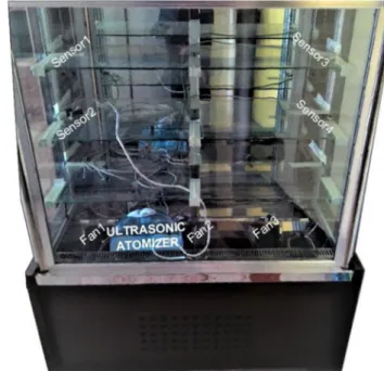
Figure12shows the developed EFLC system (unmounted)
for CRDC. CRDC (dimensions 45 cm× 1.5 m × 1 m) used in
this study and also the location of the equipment of the
devel-oped EFLC on this CRDC (mounted) are shown in Fig.13.
As the sensor 5 is located near the evaporator, it cannot be
seen in Fig.13.
2.6 Software of the System
The developed control system (EFLCS) together with PIC codes that is written to get information from sensor and to activate the actuators was transferred to microcontroller using PIC-C language with Hi-Tech PIC compiler. The inter-face software that displays the input–output values instantly
Fig. 11 The operation of the ultrasonic atomizer [47]
on the computer screen was developed using Microsoft Visual Studio Program C# language.
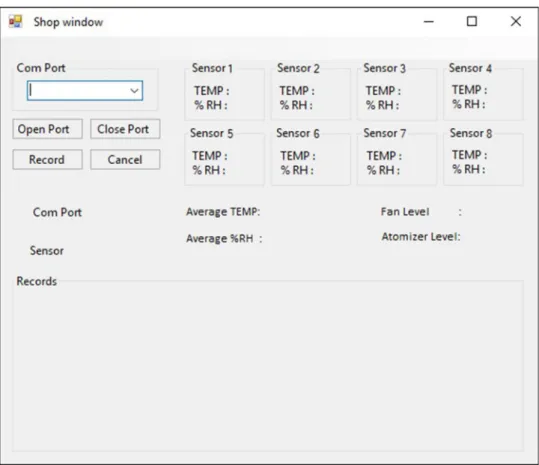
2.6.1 Software of the Interface
The interface was designed to view and record the levels of both the steam of UA and the speeds of the fans that are con-trolled by developed EFCL. The interface is provided via the Universal Synchronous/Asynchronous Receiver/Transmitter (USART) RC6 port for communication with microcontroller. A screenshot of the designed interface program is shown in
Fig.14.
Fig. 13 CRDC with developed EFLC system (mounted)
Fig. 12 Developed EFLC
Fig. 14 Screenshot of the
interface program
2.6.2 Software of Microcontroller
The inputs and outputs of the entire system are controlled by this software which is developed by using PIC-C language and transferred to microcontroller.
2.7 The Algorithm
The values (humidity and temperature) from the SHT11 sen-sors were used as inputs, and speed level of 3 simultaneously operated fans and steam level of UA were used as outputs.
As previously stated, UA is operated in levels (0–10 steps) depending on the average of the temperature and humidity values from the four sensors placed in the upper and lower parts of CRDC. Therefore, two inputs (average temperature and average humidity) and one output (steam level) EFLCS were designed for UA.
On the other hand, the speed levels of the fans depend on the temperature difference and average temperature values. The average temperature value is the average of the tempera-ture values read from the four sensors placed in the upper and lower parts of CRDC. As mentioned previously for efficient air conditioning system, the difference between the average temperature of the cooled area and temperature of cooler
liquid inside the evaporator must not exceed 5◦C. Due to
this reason, the temperature difference between evaporator
temperature and the average of the temperature values read from the four sensors placed in the upper and lower parts of CRDC is used to determine the current speed level values of the fans. Therefore, two inputs (average temperature and the temperature difference) and one output (fan speed level) EFLCS were designed for fans.
Both the code necessary for microcontroller to receive the information from the sensors and EFLCS code to operate the steam level of UA and speed levels of fan in accordance with this information were written and loaded to microcon-troller. As a final addition, microcontroller was also loaded with the codes necessary for on–off control of the
compres-sor between 3 and 5◦C to keep the temperature inside CRDC
constant at 4◦C through a relay. When the design of EFLCS
was completed, experiments were made on CRDC for dif-ferent values of humidity and temperatures.
Normally, a fuzzy system is performed in three steps: fuzzification: mapping the actual values of the variables in the fuzzy set, inference: determining the rules that should be used according to the rule base, defuzzification: determin-ing a numerical output accorddetermin-ing to the result obtained in
the Inference step [48]. In this study, Mamdani implication
method was used as inference mechanism, and the weight average method, which is most commonly used for the fuzzy applications and is limited to symmetric output membership
Fig. 15 Membership functions of average temperature input
Fig. 16 Membership functions of average humidity input
In the following sections, only the fuzzy membership functions of the inputs and outputs and also the rule tables are mentioned. The inference and defuzzification processes were carried out according to the previously mentioned methods and loaded to microcontroller.
2.8 Steam Level Control Design of UA
In FL control of UA, the average value of the temperature in CRDC for any moment is the first input value and the average value of the humidity in CRDC for any moment is the second input value. EFLCS decides at what steam level of UA will be driven according to these inputs at related moment. Depending on this decision or calculated output value, microcontroller generates a PWM signal to drive UA to reach the calculated steam level of UA at related moment.
2.8.1 Fuzzification of Inputs
The symmetric triangular membership function was used for moderate temperature (MT), tolerable temperature (TT) and high temperature (HT), whereas the trapezoidal membership function was used for low temperature (LT) and excessive temperature (ET). The average temperature input was defined
by five membership functions as shown in Fig.15.
The symmetric triangular membership function was used for low humidity (LH), tolerable humidity (TH) and moderate humidity (MH), whereas the trapezoidal membership func-tion was used for too low humidity (TLH) and high humidity (HH). The average humidity input was defined by five
mem-bership functions as shown in Fig.16.
Fig. 17 Membership functions of steam level of UA
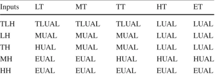
Table 3 Rule table for steam level of UA
Inputs LT MT TT HT ET
TLH TLUAL TLUAL TLUAL LUAL LUAL
LH MUAL MUAL MUAL LUAL LUAL
TH HUAL MUAL MUAL LUAL LUAL
MH EUAL EUAL HUAL HUAL HUAL
HH EUAL EUAL EUAL EUAL EUAL
2.8.2 Fuzzification of Output
The symmetric triangular membership function was used for low UA level (LUAL), moderate UA level (MUAL) and high UA level (HUAL), whereas the trapezoidal membership function was used for too low UA level (TLUAL) and exces-sive UA level (EUAL). UA steam level was defined by five
membership functions as shown in Fig.17.
2.8.3 Rule Table
The rule table for steam level of UA is shown in Table3.
2.9 Speed Level Control Design of the Fan
In FL control of the fans, the difference between the evapora-tor temperature and the average temperature inside CRDC for any moment is first input and the average temperature inside CRDC for any moment is second input. EFLCS decides at what speed levels of fans will be driven according to these inputs at related moment. Depending on this decision or calculated output value, microcontroller generates a PWM signal for the YASKAWA V1000 driver to produce an output voltage value from 0 to 10 V to drive the fans to reach the calculated speed levels of fans at related moment. So, all the fans run at the same required speed level to provide required air conditioning in CRDC.
2.9.1 Fuzzification of Inputs
The symmetric triangular membership function was used for low difference between average temperature and the evapora-tor temperature (LATET), moderate difference between
aver-Fig. 18 Membership functions of difference between average
temper-ature and evaporator tempertemper-ature
Fig. 19 Membership functions of level of fan speed
age temperature and the evaporator temperature (MATET) and high difference between average temperature and the evaporator (HATET), whereas the trapezoidal membership function was used for too low difference between average temperature and the evaporator temperature (TLATET) and excessive difference between average temperature and the evaporator (EATET). The range for the difference between the average temperature and the evaporator temperature was
defined by five membership functions as shown in Fig.18.
The second input used for fan speed control design is the average humidity. Since the fuzzification of average humidity was explained in “design of steam level control design of
UA” section (Sect.2.8), the tables and figures will not be
mentioned here again.
2.9.2 Fuzzification of Output
The symmetric triangular membership function was used for low fan speed (LFS), moderate fan speed (MFS) and high fan speed (HFS), whereas the trapezoidal membership func-tion was used for too low fan speed (TLFS) and excessive fan speed (EFS). The speed level of fan was defined by five
membership functions as shown in Fig.19. Since all fans will
run with the same speed level, the value of this output will be used to drive all fans.
2.9.3 Rule Table
The rule table for speed level of fan is shown in Table4.
Table 4 Rule table for speed level of fan
Inputs TLATET LATET MLATET HLATET ELATET
LT TLFS TLFS LFS LFS LFS
MT TLFS LFS LFS LFS LFS
TT LFS MFS MFS MFS LFS
HT HFS EFS MFS MFS MFS
ET EFS EFS HFS MFS MFS
Fig. 20 Comparative graph of EFLCS and traditional system regarding
the instantaneous temperature control
3 Results and Discussions
For comparison aim, the records (temperature and humidity) taken from sensors at certain intervals (13.7 s) were trans-ferred to the computer. By using these records, graphics were obtained by Originlab program. First, the records of classical system were kept and then the records of developed EFLCS were kept using the same CRDC. Experiments were
car-ried out at 23◦C outdoor temperature and 55% RH outdoor
humidity. The comparative graph of EFLCS and traditional system regarding the instantaneous temperature control is
shown in Fig. 20. First of all, equal and long-term
opera-tion was carried out to stabilize both systems. Then, both systems were provided to continue running for 850 s more. According to the test results, the maximum temperature of the
traditional system is 5.56◦C and the minimum temperature
is 3.2◦C. For EFLCS, the maximum temperature is 4.44◦C
and the minimum temperature is 3.69◦C. Considering that
both systems are set at+ 4◦C, it seems that EFLCS has less
temperature fluctuation than traditional system.
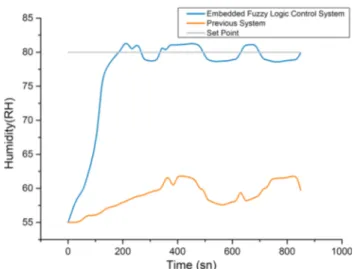
The comparative graph of EFLCS and traditional system regarding the instantaneous humidity control is shown in
Fig.21. The humidity control results were obtained on the
same conditions as the temperature test. According to the test results, the maximum humidity and minimum humidity
Fig. 21 The comparative graph of EFLCS and traditional system
regarding the instantaneous humidity control
Fig. 22 The comparative graph of EFLCS and traditional system
regarding the reaching temperature set point
of traditional system are 61.81% RH and 57.45% RH, respec-tively. Regarding EFLCS, the maximum humidity is 81.33% RH and the minimum humidity is 78.57% RH. Considering that both systems are set at 80% RH, it seems that EFLCS has obtained less humidity fluctuation around the set value whereas traditional system even could not reach the set value. The comparative graph of EFLCS and traditional
sys-tem regarding the reaching sys-temperature set point (+ 4◦C)
is shown in Fig.22. The time of reaching the set point was
measured instantly for both systems starting at+ 7◦C.
Tra-ditional system reached set value at 191.8 s and EFLCS at 109.6 s. EFLCS reached set value 82.2 s earlier than tradi-tional system.
The comparative graph of EFLCS and traditional system regarding the reaching humidity set point (80% RH) is shown
in Fig.23. The time of reaching the set point was measured
instantly for both systems starting at 55% RH. Traditional
Fig. 23 The comparative graph of EFLCS and traditional system
regarding reaching the humidity set point
system could not reach the set value (could only reach 60% RH in 342.5 s), whereas EFLCS reached set value in 191.8 s.
4 Conclusions
In traditional CRDC produced in Turkey, generally only tem-perature on–off control is carried out. In the pastry sector, especially, the moisture level required for daily produced products cannot be ensured, which leads to a short shelf life. In this study, EFLCS for CRDC was developed to make the shelf life of the cakes longer than it was before. Devel-oped EFLCS kept CRDC temperature and humidity values
required for cakes at approximately + 4◦C and 80% RH,
respectively. In addition, this study contributed to the liter-ature by adding FL to the system developed by the authors
[50]. This study is a rare study in which PWM- and
FL-based control system is used in the field of climate control. Additionally, UA is used for the first time to supply required humidity in CRDC manufactured in Turkey. Thus, a different approach to this area is presented in this study.
As mentioned previously for efficient air conditioning sys-tem, the difference between the average temperature of the cooled area and temperature of cooler liquid inside the
evap-orator must not exceed 5◦C. With developed EFLCS, this
difference is kept under 5◦C and the snow on the evaporator
surface was tried to be minimized to increase efficiency of evaporator.
Within the scope of the study, UA could be developed and the compressor could be driven at different speeds. Since each one is the topic of different fields, available UA and on–off control system were used during the compressor’s operating periods. The authors of this work on the one side continue
to work to drive the compressor at different speeds, on the other side experimenting to demonstrate the superiority of EFLCS’s energy consumption over as per traditional system. In this context, three test forms (MIL/SIL/PIL) that are successful and cost-effective solutions for automotive and
aerospace embedded systems [51] can be used in FLC
algo-rithms to be developed.
Acknowledgements The works presented in this article were carried
out within the scope of the project numbered Selcuk University BAP 12101022. The authors thank Selcuk University BAP for their support.
References
1. Chaomuang, N.; Flick, D.; Denis, A.; Laguerre, O.: Experimental analysis of heat transfer and airflow in a closed refrigerated dis-play cabinet. J. Food Eng. 244, 101–114 (2019).https://doi.org/ 10.1016/J.JFOODENG.2018.09.009
2. Chaomuang, N.; Flick, D.; Laguerre, O.: Experimental and numer-ical investigation of the performance of retail refrigerated display cabinets. Trends Food Sci. Technol. 70, 95–104 (2017).https://doi. org/10.1016/J.TIFS.2017.10.007
3. Garvan, C.: Time-temperature and relative humidity profiles of chilled and frozen foods in retail outlets nationwide, and evaluation of related practices. Masters Thesis, Dublin Institute of Technology (2007).https://doi.org/10.21427/D7C468
4. Aste, N.; Pero, C.D.; Leonforte, F.: Active refrigeration tech-nologies for food preservation in humanitarian context—a review. Sustain. Energy Technol. Assess. 22, 150–160 (2017).https://doi. org/10.1016/j.seta.2017.02.014
5. Labuza, T.; Hyman, C.: Moisture migration and control in multi-domain foods. Trends Food Sci. Technol. 9(2), 47–55 (1998).
https://doi.org/10.1016/S0924-2244(98)00005-3
6. James, S.; James, C.: Refrigeration, storage and transport of chilled foods. In: Brown, M. (ed.) Chilled Foods, Woodhead Publish-ing Series in Food Science, Technology and Nutrition, 3rd edn, pp. 375–403. Woodhead Publishing Limited, Cambridge (2008).
https://doi.org/10.1533/9781845694883.2.375
7. James, S.J.; Swain, M.V.L.: Retail display conditions for unwrapped chilled foods. In: Proceeding of the Institute of Refrig-eration, vol. 82, pp. 1–7 (1986)
8. Brown, T.; Corry, J.E.; James, S.J.: Humidification of chilled fruit and vegetables on retail display using an ultrasonic fogging system with water/air ozonation. Int. J. Refrig. 27(8), 862–868 (2004).
https://doi.org/10.1016/J.IJREFRIG.2004.04.009
9. Brown, M.: Introduction to chilled foods. In: Brown, M. (ed.) Chilled Foods, Woodhead Publishing Series in Food Sci-ence, Technology and Nutrition, 3rd edn, pp. 1–21. Woodhead Publishing Limited, Cambridge (2008).https://doi.org/10.1533/ 9781845694883.1
10. Evans, J.A.; Woolfe, M.L.: Temperature monitoring and measure-ment. In: Brown, M. (ed.) Chilled Foods, Woodhead Publishing Series in Food Science, Technology and Nutrition, 3rd edn, pp. 404–442. Woodhead Publishing Limited, Cambridge (2008).
https://doi.org/10.1533/9781845694883.2.404
11. Ramakrishna Rau, B.; Schlansker, M.: Embedded computer archi-tecture and automation. Computer 34, 75–81 (2001).https://doi. org/10.1109/2.917544
12. Olsson, P.: Chill cabinet surveys. In: Zeuthen, P.; Cheftel, J. C.; Eriksson C.; Gormley TR.; Linko P.; Paulus, K. (eds.) Processing and Quality of Foods, vol. 3, pp. 3.279–3.288. Elsevier Applied Science, London and New York (1990)
13. Willocx, F.; Hendrick, M.; Tobback, P.: A preliminary survey into the temperature conditions and residence time distribution of minimally processed map vegetables in belgian retail display cabi-nets. Int. J. Refrig. 17(7), 436–444 (1994).https://doi.org/10.1016/ 0140-7007(94)90003-5
14. Gill, C.; Jones, T.; Houde, A.; LeBlanc, D.; Rahn, K.; Holley, R.; Starke, R.: The temperatures and ages of packs of beef displayed in multi-shelf retail cabinets. Food Control 14(3), 145–151 (2003).
https://doi.org/10.1016/S0956-7135(02)00058-0
15. Derens, E.; Palagos, B.; Guilpart, J.: The cold chain of chilled products under supervision in France. In: 13th World Congress of Food Science and Technology 2006, pp. 823 – 823 (2006).https:// doi.org/10.1051/IUFoST:20060823
16. Derens-Bertheau, E.; Osswald, V.; Laguerre, O.; Alvarez, G.: Cold chain of chilled food in France. Int. J. Refrig. 52, 161–167 (2015).
https://doi.org/10.1016/j.ijrefrig.2014.06.012
17. Sagoo, S.K.; Little, C.L.; Allen, G.; Williamson, K.; Grant, K.A.: Microbiological safety of retail vacuum-packed and modified-atmosphere-packed cooked meats at end of shelf life. J. Food Prot.
70(4), 943–951 (2007).https://doi.org/10.4315/0362-028X-70.4. 943
18. Koutsoumanis, K.; Pavlis, A.; Nychas, G.J.E.; Xanthiakos, K.: Probabilistic model for listeria monocytogenes growth during dis-tribution, retail storage, and domestic storage of pasteurized milk. Appl. Environ. Microbiol. 76(7), 2181–2191 (2010).https://doi. org/10.1128/AEM.02430-09
19. Sulistyanto, M.P.T.; Harianto, W.; Nugroho, D.A.; Retandi, R.E.; Akbar, A.K.; Tjahjanti, P.H.: The controlling and monitoring sys-tem in oyster mushroom cultivation using fuzzy logic through web technology integrated with Internet of Things. In: MATEC Web of Conferences , vol. 197, p. 15002 (2018).https://doi.org/10.1051/ matecconf/201819715002
20. Kamis, M.; Abdullah, A.; Sudin, S.; Shukor, S.; Bakar, M.; Mustafa, M.: Closed house chicken barn climate control using fuzzy infer-ence system. J. Telecommun. Electron. Comput. Eng. 10(1–14), 47–51 (2018)
21. Ali, M.; Abdelwahab, M.; Awadekreim, S.; Abdalla, S.: Develop-ment of a monitoring and control system of infant incubator. In: 2018 International Conference on Computer, Control, Electrical, and Electronics Engineering (ICCCEEE), pp. 1–4 (2018).https:// doi.org/10.1109/ICCCEEE.2018.8515785
22. Heidari, M.; Khodadadi, H.: Climate control of an agricultural greenhouse by using fuzzy logic self-tuning PID approach. In: ICAC 2017-2017 23rd IEEE International Conference on Automa-tion and Computing: Addressing Global Challenges through Automation and Computing, pp. 1–6 (2017). https://doi.org/10. 23919/IConAC.2017.8082074
23. Omer, S.A.U.R.; Muhammad, E.: Design of intelligent air con-ditioner controller using fuzzy logic. In: ICIEECT 2017— International Conference on Innovations in Electrical Engineering and Computational Technologies 2017, Proceedings, pp. 1–5 (2017).https://doi.org/10.1109/ICIEECT.2017.7916556
24. Sathish, K.A.; Sudha, S.: Hardware realization of fuzzy logic driven PWM controller for a cold storage system. In: 2017 2nd IEEE International Conference on Recent Trends in Electronics, Information Communication Technology (RTEICT), pp. 236–240 (2017).https://doi.org/10.1109/RTEICT.2017.8256593
25. Algarín, C.R.; Cabarcas, J.C.; Llanos, A.P.: Low-cost fuzzy logic control for greenhouse environments with web mon-itoring. Electronics 6(4), 71 (2017). https://doi.org/10.3390/ electronics6040071
26. Laksono, P.W.; Jauhari, W.A.; Iftadi, I.; Christina Ayu, K.; Ibnu Pandu, B.P.; Jamaluddin, A.; Saputro, D.E.; Haijunowibowo, D.: A system based on fuzzy logic approach to control humidity and temperature in fungus cultivation. In: Proceedings - Joint Interna-tional Conference on Electric Vehicular Technology and Industrial,
Mechanical, Electrical and Chemical Engineering, ICEVT 2015 and IMECE 2015, pp. 344–347 (2015).https://doi.org/10.1109/ ICEVTIMECE.2015.7496716
27. Dwi Teguh, R.; Didik Eko, S.; Laksono, P.D.; Jamaluddin, A.: The design of an embedded system for controlling humidity and temperature room. In: Journal of Physics: Conference Series, vol. 776, no. 1, p. 012096 (2016).https://doi.org/10.1088/1742-6596/ 776/1/012096
28. Bansal, H.; Mathew, D.L.; Gupta, A.: Controlling of temperature and humidity for an infant incubator using microcontroller. Int. J. Adv. Res. Electr. Electron. Instrum. Eng. 04(06), 4975–4982 (2015).https://doi.org/10.15662/ijareeie.2015.0406012
29. Mirzaee-Ghaleh, E.; Omid, M.; Keyhani, A.; Dalvand, M.: Com-parison of fuzzy and on/off controllers for winter season indoor climate management in a model poultry house. Comput. Electron. Agric. 110, 187–195 (2015).https://doi.org/10.1016/J.COMPAG. 2014.11.017
30. Yan, H.; Xia, Y.; Xu, X.; Deng, S.: Inherent operational charac-teristics aided fuzzy logic controller for a variable speed direct expansion air conditioning system for simultaneous indoor air tem-perature and humidity control. Energy Build. 158, 558–568 (2018).
https://doi.org/10.1016/J.ENBUILD.2017.10.013
31. Jeong, S.K.; Han, C.H.; Hua, L.; Wibowo, W.K.: Systematic design of membership functions for fuzzy logic control of variable speed refrigeration system. Appl. Therm. Eng. 142, 303–310 (2018).
https://doi.org/10.1016/J.APPLTHERMALENG.2018.06.082
32. Asraf, H.M.; Dalila, K.A.N.; Hakim, A.W.M.; Hon, R.H.M.F.: Development of experimental simulator via Arduino-based PID temperature control system using LabVIEW. J. Telecommun. Elec-tron. Comput. Eng. (JTEC) 9(15), 53–57 (2017)
33. Zhong, Z.; Xu, X.; Zhang, X.; Huang, Z.: Simulation based control performance evaluation of a novel fuzzy logic control algorithm for simultaneously controlling indoor air temperature and humid-ity using a direct expansion (DX) air-conditioning (A/C) system. Procedia Eng. 205, 1792–1799 (2017).https://doi.org/10.1016/J. PROENG.2017.10.040
34. Huang, Y.; Khajepour, A.; Ding, H.; Bagheri, F.; Bahrami, M.: An energy-saving set-point optimizer with a sliding mode controller for automotive air-conditioning/refrigeration systems. Appl. Energy 188, 576–585 (2017). https://doi.org/10.1016/J. APENERGY.2016.12.033
35. Ahamed, N.U.; Yusof, Z.; Hamedon, Z.; Rabbi, M.F.; Sikan-dar, T.; Palaniappan, R.; Ali, M.A.; Rahman, S.M.; Sundaraj, K.: Fuzzy logic controller design for intelligent drilling system. In: Proceedings—2016 IEEE International Conference on Automatic Control and Intelligent Systems, I2CACIS 2016, pp. 208–213 (2017).https://doi.org/10.1109/I2CACIS.2016.7885316
36. Meana-Llorián, D.; González García, C.; Pelayo G-Bustelo, B.C.; Cueva Lovelle, J.M.; Garcia-Fernandez, N.: IoFClime: the fuzzy logic and the internet of things to control indoor temperature regard-ing the outdoor ambient conditions. Futur. Gener. Comput. Syst.
76, 275–284 (2017)
37. Almasani, S.A.M.; Qaid, W.A.A.; Khalid, A.; Alqubati, I.A.A.: Fuzzy expert systems to control the heating, ventilating and air conditioning (HVAC) systems. Int. J. Eng. Res. Technol. (IJERT)
4(8), 808 (2015)
38. Sulaiman, N.A.; Othman, M.F.; Abdullah, H.: Fuzzy logic control of centralized chilled water system. Jurnal Teknologi 72(2), 57–62 (2015).https://doi.org/10.11113/jt.v72.3884
39. Heath, S.: Embedded Systems Design, 2nd edn. Elsevier, Amster-dam (2003)
40. Ajao, L.A.; Agajo, J.; Kolo, J.G.; Adegboye, M.A.; Yusuf, Y.: Learning of embedded system design, simulation and implementa-tion: a technical approach. Am. J. Embed. Syst. Appl. 3(3), 35–42 (2016).https://doi.org/10.11648/J.AJESA.20150303.12
41. Kaewwiset, T.; Yodkhad, P.: Automatic temperature and humid-ity control system by using Fuzzy Logic algorithm for mushroom nursery. In: 2nd Joint International Conference on Digital Arts, Media and Technology 2017: Digital Economy for Sustainable Growth, ICDAMT 2017, pp. 396–399 (2017).https://doi.org/10. 1109/ICDAMT.2017.7905000
42. Senririon: SHT1X/SHT7X humidity&temperature sensor.http:// www.sensirion.com/fileadmin/userupload/customers/sensirion/ Dokumente/Humidity/SensirionHumiditySHT1xDatasheetV5. pdf. Accessed 3 May 2015
43. YASKAWA: YASKAWA V1000 cheat sheet.https://www.galco. com/techdoc/yask/v1000_qr.pdf. Accessed 18 Nov 2018 44. PTdesign: Pulse–width modulation.http://fab.cba.mit.edu/classes/
961.04/topics/pwm.pdf. Accessed 21 Nov 2018
45. Derrick, J.: How ultrasonic humidifiers work—principle of operation. https://blog.stulz-usa.com/how-ultrasonic-humidifiers-work. Accessed 8 Nov 2018
46. Stulz: ultrasonic humidifier function principle.https://www.stulz. de/en/ultrasonic/function-principle/. Accessed 8 Nov 2018 47. Honda Electronics: Ultrasonic Atomizer Unit.
https://www.honda-el.co.jp/ufile/library/1362_file.png. Accessed 8 July 2018 48. Szesz Junior, A.; Monteiro Junior, M.; Dias, A.H.; Mathias,
I.M.; Conti, G.: Embedded system in Arduino platform with Fuzzy control to support the grain aeration decision. Ciência Rural 46(11), 1917–1923 (2016). https://doi.org/10.1590/0103-8478cr20141808
49. Ross, T.J.: Fuzzy Logic with Engineering Applications, 3rd edn. Wiley, Hoboken (2010)
50. Tutuncu, K.; Ozcan, R.: Design of air conditioning automation for patisserie shopwindow. World Acad. Sci. Eng. Technol. Int. J. Electr. Comput. Energ. Electron. Commun. Eng. 7(8), 123–126 (2013)
51. Motahhir, S.; El Ghzizal, A.; Sebti, S.; Derouich, A.: MIL and SIL and PIL tests for MPPT algorithm. Cogent Eng. 4(1), 1378475 (2017).https://doi.org/10.1080/23311916.2017.1378475
![Fig. 1 Bacterial growth rate for human pathogens at different temper- temper-atures [4]](https://thumb-eu.123doks.com/thumbv2/9libnet/5388062.101440/2.892.78.430.83.261/bacterial-growth-human-pathogens-different-temper-temper-atures.webp)