http://dx.doi.org/10.1080/01694243.2016.1204144
Effect of material and fabrication technique on marginal fit
and fracture resistance of adhesively luted inlays made of
CAD/CAM ceramics and hybrid materials
Işıl Damla Sener-Yamanera, Atilla Sertgözb, Tugba Toz-Akalınc and Mutlu Özcand afaculty of dentistry, department of Prosthodontics, İstanbul aydın university, istanbul, Turkey; bfaculty
of dentistry, department of Prosthodontics, Marmara university, istanbul, Turkey; cschool of dentistry,
department of restorative dentistry, istanbul Medipol university, istanbul, Turkey; dclinic for fixed and
removable Prosthodontics and dental Materials science, dental Materials unit, center for dental and oral Medicine, university of Zurich, Zurich, switzerland
ABSTRACT
This study evaluated the fracture resistance and marginal fit of CAD/ CAM ceramic and composite inlays. Molars (N = 80) were prepared to receive Mesio-occlusal-distal (MOD) inlays and randomly divided into four groups to be restored depending on the materials: (a) HLD: heat-pressed lithium disilicate ceramic (IPS e.max Press), (b) CLD: CAD/CAM-fabricated lithium disilicate ceramic (IPS e.max CAD), (c) NC: CAD/CAM nano-ceramic resin (Lava Ultimate), (d) RC: Indirect resin composite (Filtek P60). Each group was randomly divided into two subgroups regarding the resin cement: (a) High-viscosity resin cement (Syntac, Variolink II), (b) Self-adhesive low-viscosity cement (RelyX Ultimate). After marginal gap and cement thickness measurements, specimens were loaded to fracture in a Universal Testing Machine (1 mm/min). Intact molars acted as the control group (n = 10). Data were analyzed using one-way and two-way ANOVA, Tukey’s tests (α = 0.05). Before cementation, CLD group showed significantly lower mean marginal gap (65 ± 22.4 μm) and after cementation, cement thickness was again the lowest with CLD (82.6 ± 24.6 μm) and the highest with HLD (108.4 ± 21.3 μm) (p < 0.001). The mean marginal gaps of inlays at the gingival margin were significantly higher than at the occlusal and the axial margins (p < 0.05). While material type significantly affected the mean fracture resistance (p < 0.001), the cement type had no effect on the results (p = 0.083). NC group (2486 ± 40 N) showed significantly higher mean fracture load compared to those of other three groups (1997.5 ± 60–2007 ± 30) (p < 0.05). The mean fracture resistance of control group with the intact teeth was significantly higher than those of all groups (p < 0.05) except for NC (p > 0.05).
Introduction
Minimal invasive direct dental restorative materials may not provide adequate anatomy or contact with the neighboring teeth depending on the tissue loss. In such conditions, indirect inlays made of alloys, resin composite, or ceramic materials may be indicated. Among all
KEYWORDS
cad/caM; cement thickness; marginal gap; nano-ceramic resin composite; resin cement; inlay
ARTICLE HISTORY
received 26 february 2016 revised 8 June 2016 accepted 15 June 2016
© 2016 informa uK limited, trading as Taylor & francis group
these material options, ceramic inlays are mainly composed of glass with crystalline mate-rials added to increase their strength.[1] They can be manufactured in a laboratory using a press technique or can be milled chair-side from prefabricated ceramic blocks with the help of computer-aided design/computer-aided manufacturing (CAD/CAM) technology. [2] Indirect resin composite inlay restorations can be polymerized with light, heat, and/or pressure outside the oral environment, and then luted to the tooth with resin composite cement.[3,4]
Recently, resin composite blocks have also become available for use in CAD/CAM resto-rations, opening up a wider range of material options.[5] Industrial manufacturing of such materials permits the use of post-polymerization methods that deliver improved mechanical properties compared to direct resin composite materials.[3,4] Due to the fact that resin materials are less brittle as opposed to ceramics, thinner reconstructions could be made with indirect composites that allow for more conservative preparation designs and more resistant restorations.[5]
The success of an inlay restoration is determined by three main factors, namely optical properties, resistance to fracture, and marginal adaptation. Marginal and internal fit is one of the most important criteria for the clinical quality and success of an inlay restoration. Marginal discrepancies in inlay restorations can increase the rate of cement dissolution and of microleakage.[6,7] In vitro studies revealed mean marginal gaps of 50–60 μm in CAD/ CAM-generated ceramic inlay restorations.[6,7] Similar values of between 52 and 99 μm have been reported for ceramic inlays produced by laboratory pressing methods. However, currently, limited information is available concerning the marginal fit of inlays produced using resin composite CAD/CAM systems.[8]
Fracture resistance is another crucial factor that increases the lifespan of an inlay res-toration. Some previous studies reported no significant differences in fracture resistance between ceramic and composite MOD inlays fabricated using CAD/CAM systems.[9,10] However, some other studies reported higher fracture resistance with ceramic inlays com-pared to laboratory-processed composite inlays.[11,12]
The objectives of this study therefore were to investigate the fracture resistance and marginal fit of inlay restorations fabricated from heat-pressed ceramic and machinable CAD/CAM ceramic and composite inlays luted using high- or low-viscosity luting agents. The null hypotheses tested were that neither the (a) material nor (b) the cement type would show significant difference in the marginal adaptation and the fracture resistance of inlays with different materials.
Materials and methods
Specimen preparation
The study sample consisted of extracted human first molars (N = 90) with similar morphol-ogy and no decay or wear (IRB serial number: B.30.2.AYD.0.00.00-480.2/011). In order to minimize the influence of size and shape variations on the experimental results, the teeth were classified according to their mesio-distal (10.5 mm) and buccolingual dimensions (10.9 mm)
and the variation did not exceed 10% of the mean values.[13] Initially, any remaining soft
tissues were removed using scalers under running water. Hand instrumentation was used to remove the debris from the tooth surfaces, and tooth surfaces were cleaned with rubber
cup and pumice slurry. The teeth were stored in 0.1% thymol solution until the experiments. Experimental sequences are presented in Figure 1.
All teeth were mounted in auto-polymerizing resin (Meliodent, Heraeus Kulzer GmbH, Hanau, Germany) (diameter: 2.5 cm) in cylinder blocks up to 2 mm apical to the cemen-to-enamel junction. Before preparation, the teeth were rinsed under tap water and placed in deionized water at room temperature for 24 h.[10]
A silicon impression (Zetaflow, Zhermack, Rovigo, Italy) was made of each tooth prior to preparation. Then, the teeth were sectioned in a buccolingual direction to control the volume of tooth structure removed during preparation.[8] Eighty teeth were prepared for testing using a high-speed angled hand piece connected to a parallelometer (Kavo EWL Type 990, Leutkirch, Germany) and diamond rotary cutting instruments (Inlay preparation set 4261; Komet, Gebr. Brasseler, Lemgo, Germany) under water-cooling. Diamond rotary cutting instruments were discarded after every four preparations.[14] All teeth were prepared by the same operator to eliminate inter-operator differences. MOD cavities were prepared for an inlay restoration where the isthmus was 3 mm in both depth and width. The overall
Figure 1. flow chart showing experimental sequence and allocation of groups. hld: heat-pressed lithium
disilicate ceramic (iPs e.max Press), cld: cad/caM-fabricated lithium disilicate ceramic (iPs e.max cad), nc: cad/caM-fabricated nano-ceramic resin (lava ultimate), d) rc: indirect resin composite (filtek P60).
preparation angle was set to 6° toward the occlusal aspect. The mesial and distal finishing lines of the rounded boxes were established 1 mm above the cemento-enamel junction. The box width was 1.5 mm mesio-distally (Figure 2). All inner cavity angles were rounded and all surfaces were smoothed with fine diamond burs (Inlay/Onlay Expert set 4562, Komet).[8] Inlay fabrication
The prepared teeth were randomly divided into four groups to be restored with the follow-ing materials:
HLD: Inlays were fabricated using heat-pressed lithium disilicate ceramic (IPS e.max Press) using a press technique.
CLD: Inlays were fabricated using CAD/CAM-fabricated lithium disilicate ceramic (IPS e.max CAD) using a CAD/CAM system.
NC: In this group, Inlays were fabricated using CAD/CAM-fabricated nano-ceramic resin (Lava Ultimate) using a CAD/CAM system.
RC: Inlays were fabricated using high-viscous resin composite (Filtek P60) employing incremental direct filling technique (Filtek P60, 3M ESPE) in a commercial dental laboratory according to the manufacturer′s recommendations.
C: Non-prepared teeth (n = 10) acted as the control group.
Impressions were made according to the double-mixing technique using a combina-tion of a regular- and heavy-body vinyl-polysiloxane material (Affinis, Coltene/Whaledent AG, Altstatten, Switzerland). The regular-body material was applied to the prepared tooth with a syringe, while the heavy-body material was placed on a perforated custom-made template. Die stone models were cast in a vacuum-mixed die stone (GC Fujirock EP; GC Europe NV, Leuven, Belgium Die stone models in the CLD and NC groups were scanned using the CEREC system as part of the EOS system (Sirona, Bensheim, Germany). Prior to the fabrication of the restorations in the CAD/CAM groups, the internal and marginal gaps
Figure 2. Measurement points and dimensions of inlay (o: occlusal; g: gingival; a: axial, x: isthmus width
were set to 30 μm. Virtual MOD inlays were constructed using a software (Cerec in Lab 3D, Version 4.2.1, Sirona). For groups CLD and NC, CAD/CAM inlays were generated by the Cerec 4 CAD/CAM System using a CEREC milling machine (MC XL, Sirona) with an average thickness of 3 mm at the central groove. In order to standardize the form and anatomy, the original design of the restoration was not edited but only the position tools were used to ensure the correct thickness. The inlay in CLD and NC group were milled from pre-sintered lithium disilicate glass ceramic blocks (IPS e.max CAD, LTA1, C14, Ivoclar Vivadent, Schaan, Liechtenstein) and preformed nano-ceramic composite resin blocks (Lava Ultimate, 3M ESPE, St. Paul, USA), respectively.
HLD group inlays were fabricated from a pressable lithium disilicate glass ceramic (IPS e.max Press, Ivoclar Vivadent) using the lost-wax technique. Two layers of die spacer (Euro Quick Set, Kerr Dental Laboratory Products, Bioggio, Switzerlad) were applied to the die stones of HLD and RC inlays. The layers were applied uniformly with a brush, starting 1 mm short of the finish lines of the preparations. Anatomic contour waxing was created for HLD inlays which were then invested with fine-grained phosphate-bonded investment material (Multi Press Vest, GC America Inc., Alsip, IL, USA). Finally, the pressing process was completed according to the manufacturer’s instructions.
The inlays used in the HLD, CLD, NC groups were mechanically polished using a commercial polishing kit (Kit 4477, QPolishing System, Komet, Lemgo, Germany) while group RC inlays were finished using 15-μm fine diamond burs (Intensiv SA) and polishing disks from coarse to fine (Soflex, 3 M ESPE) under a continuous stream of cool water.[15]
Restorative procedures
After polishing procedures, inlays were placed into the respective cavities and their fit was ensured with low-viscosity polyvinylsiloxane (Fit Checker, GC, Tokyo, Japan). The teeth in each group were then divided into two subgroups (n = 10 per group) to be cemented with either high-viscosity cement (Etch-and-rinse adhesive Syntac System, Variolink II, Ivoclar Vivadent) or low-viscosity resin cement (Self-etch adhesive, RelyX Ultimate, 3 M ESPE). Although viscosity of the tested cements was not measured, they were described as ‘high’ and ‘low viscosity’ according to the manufacturer’s classifications.
For the cementation procedures of high-viscosity cement, tooth surfaces were cleaned with water, air-dried, and etched for 30 s with 37% phosphoric acid (Total Etch, Ivoclar Vivadent). After rinsing and drying, primer (Syntac primer, Ivoclar Vivadent) was applied for 15 s, the teeth were dried again, and adhesive resin (Syntac adhesive, Ivoclar Vivadent) was applied for 10 s and allowed to dry.
The internal surfaces of the ceramic inlays were first cleaned with water, air-dried, etched for 60 s with 4% hydrofluoric acid (Porcelain Etchant, Bisco, Inc., Schaumburg, IL), rinsed for 60 s, and air-dried. Then, silane coupling agent (Monobond Plus, Ivoclar Vivadent) was applied and allowed to react for 60 s and air-dried. The internal surfaces of the com-posite inlays were air-abraded with 50-μm aluminum oxide (Mega-Strahlkorund, Mega Dental, Budingen, Germany) for 5 s and then cleaned with ethanol, according to the man-ufacturer’s recommendations. Following this preparation, a thin layer of adhesive resin (Heliobond, Ivoclar Vivadent) was applied to both the inner surfaces of the inlays and the tooth surfaces. The inlays were first manually and then ultrasonically seated (Sirona,
Dentsply, Bensheim, Germany) with a high-viscosity composite luting cement (Variolink Veneer, Ivoclar Vivadent) and photo-polymerized (Bluephase, Ivoclar, Vivadent, Schaan, Liechtenstein; light output: 1200 mw/cm2) for 15 s from each direction, according to the
manufacturer’s directions. Excess luting agent was removed carefully with a brush. Margins were covered with glycerin gel (Liquid Strip, Ivoclar Vivadent) to avoid formation of oxy-gen-inhibited layer.
For the cementation procedures of low-viscosity resin cement, the teeth were rinsed and dried and self-etch adhesive (Scotchbond Universal, 3 M ESPE) was applied for 10 s and allowed to dry. The internal surfaces of inlays were also coated with one layer of silane- incorporated adhesive (Scotchbond Universal, 3 M ESPE) for 20 s and photo-polymerized for 10 s. The difference in this group compared to the high-viscosity one was that a separate silane primer was not applied and tooth surfaces were not etched. Auto-mixed cement was applied and photo-polymerized for 20 s, according to the manufacturer’s instructions. All inlays were loaded under 1 kg of force for 1 min and excess resin was removed as described above.
Marginal gap measurement
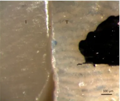
The marginal gap between the inlay and each tooth was measured using an optical micro-scope (Leica Optical Micromicro-scope, Leica Cambridge, Cambridge, UK) at 18 pre-selected locations being six at the occlusal, eight in the axial region, and four at the gingival margins at ×200 magnification before and after cementation (Figure 3). These points were marked before cementation so that they could be used as a reference for the measurements after cementation. The marginal gap was calculated as the shortest distance between the enamel cavosurface margins and the inlays at the measuring points.[16]
Fracture test
Following the cementation procedure, the teeth were stored in distilled water at 37 °C for 7 days prior to fracture test.[9] Load was applied with 6-mm-diameter stainless steel sphere in contact with both the tooth and inlay surfaces, placed on the central fossa of the occlusal surface in a Universal Testing Machine (Shimadzu AG-IS, Kyoto, Japan) and axial compressive load was applied along the long axis of each tooth at a speed of 0.5 mm/min until final fracture occurred.[13,15–17] A 1-mm-thick sheet of aluminum foil (Copyplast 1.0, ScheuDental, Germany) was inserted between the occlusal surface of the tooth and the loading jig in order to disperse the loading stress more evenly.[10] The testing instrument software recorded the maximum vertical load at the point of fracture for each type of inlay.
After the fracture resistance test, the fracture mode for each tooth was classified using a modified version of previous classifications [17,18]: Mode I: Isolated fracture of the res-toration; Mode II: Restoration fracture involving a small tooth portion; Mode III: Fracture involving more than half of the tooth, without periodontal involvement; Mode IV: Fracture with periodontal involvement.
Statistical analysis
Data were analyzed using a statistical software package (IBM SPSS Statistics 22 software package, IBM SPSS Inc., Chicago, IL). Kolmogorov–Smirnov and Shapiro–Wilk tests were used to test normal distribution of the data. As the data were normally distributed, repeated measures of one-way and two-way analysis of variance (ANOVA), Tukey’s HDS test, and the paired sample t-tests were used. Pearson’s correlation coefficient was calculated for possible relation between fracture resistance and cement thickness for each inlay material. P values less than 0.05 were considered to be statistically significant in all tests.
Results
Marginal gap and cement thickness
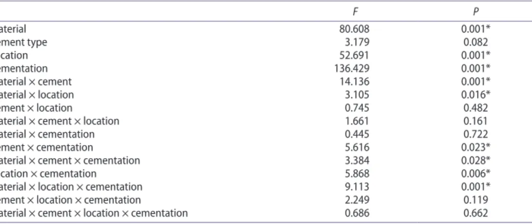
Mean marginal gap values for inlay materials were significantly affected by the inlay material (p < 0.001), location of the margins (p < 0.001) but not the cement type (p = 0.082) as shown in(Table 1). The effect of cement type was found to be statistically not significant (p > 0.05).
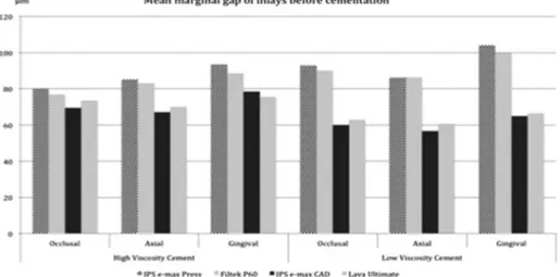
Before cementation, CLD group showed significantly lower mean marginal gap value (65 ± 22.4 μm) and after cementation, cement thickness was again the lowest with CLD (82.6 ± 24.6 μm) and the highest with HLD (108.4 ± 21.3 μm) (p < 0.001) (Table 2, Figure 4).
The mean marginal gaps of inlays at the gingival margin were significantly higher than at the occlusal and the axial margins (p < 0.05). After cementation, statistically significant differences were found between the gingival, axial, and occlusal margins for all groups (p < 0.01). Cement thickness values were significantly higher in all inlay groups after cemen-tation with both high- and low-viscosity cements (p < 0.01) (Figure 5).
Fracture and failure mode
While material type significantly affected the mean fracture resistance (p < 0.001), the cement type had no effect on the results (p = 0.083) (Table 3).
NC group (2486 ± 40 N) showed significantly higher mean fracture resistance compared to those of other three groups (1997.5 ± 60–2007 ± 30) (p < 0.05) (Table 4). No significant differences were observed between the CLD (2007 ± 30 N) and HLD groups (1997.5 ± 6 N) (p > 0.05). The mean fracture resistance of control group with the intact teeth was signifi-cantly higher than those of all groups (p < 0.05) except for NC (p > 0.05).
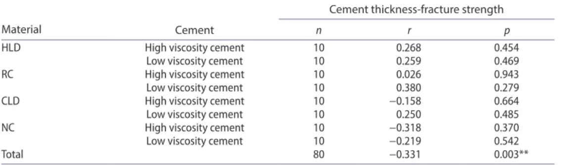
No significant correlation was found between the cement thickness and mean fracture resistance for individual materials in combination with two resin cements (p > 0.05) (Table 5). Overall correlation coefficient was weak (r = −0.331).
Failure types were predominantly Mode I and II in groups NC and RC and Mode III and IV in groups HLD and CLD (Table 6).
Table 1. results of repeated measures of two-way anoVa analyzing the effect of the material, location,
cement on marginal fit.
F P Material 80.608 0.001* cement type 3.179 0.082 location 52.691 0.001* cementation 136.429 0.001* Material × cement 14.136 0.001* Material × location 3.105 0.016* cement × location 0.745 0.482 Material × cement × location 1.661 0.161 Material × cementation 0.445 0.722 cement × cementation 5.616 0.023* Material × cement × cementation 3.384 0.028* location × cementation 5.868 0.006* Material × location × cementation 9.113 0.001* cement × location × cementation 2.249 0.119 Material × cement × location × cementation 0.686 0.662
Table 2. Mean marginal gap, cement thickness (+standard deviation) (μm) of inlays made of different
materials and cemented with either high- or low-viscosity cement (one-way anoVa, paired sample
t-test).
Note. hld: heat-pressed lithium disilicate ceramic (iPs e.max Press), cld: cad/caM-fabricated lithium disilicate ceramic (iPs e.max cad), nc: cad/caM-fabricated nano-ceramic resin (lava ultimate), d) rc: indirect resin composite (filtek P60). p < 0.05.
Cement Location
HLD RC CLD NC
P Mean ± SD Mean ± SD Mean ± SD Mean ± SD
High viscosity occlusal Before 80.03 ± 11.41 76.67 ± 12.17 69.47 ± 21.83 73.67 ± 22.11 0.011* after 105.0 ± 17.6 101.97 ± 18.01 78.08 ± 15.64 80.9 ± 15.22 0.001* axial Before 85.14 ± 13.71 83.2 ± 13.6 67.19 ± 25.65 70.08 ± 26.09 0.001* after 100.35 ± 24.17 96.6 ± 25.89 70.24 ± 16.74 72.09 ± 16.45 0.001* gingival Before 93.45 ± 17.05 88.78 ± 15.74 78.43 ± 25.08 75.5 ± 15.3 0.001* after 110.38 ± 13.47 108.9 ± 13.53 107.53 ± 17.58 109.45 ± 14.03 0.853 Low viscosity occlusal Before 92.8 ± 15.24 90.22 ± 13.41 59.9 ± 10.97 63.0 ± 8.78 0.001*
after 104.18 ± 22.82 101.92 ± 24.91 80.33 ± 25.82 82.0 ± 23.18 0.001* axial Before 86.25 ± 10.03 86.25 ± 8.01 56.75 ± 17.69 60.74 ± 16.02 0.001* after 114.93 ± 21.42 111.08 ± 23.3 76.65 ± 19.72 78.98 ± 17.51 0.001* gingival Before 104.05 ± 17.5 99.45 ± 16.3 64.95 ± 26.97 66.45 ± 27.28 0.001* after 120.68 ± 13.55 118.15 ± 14.26 104.15 ± 31.58 107.13 ± 31.29 0.005* Total Before 88.84 ± 15.37 86.38 ± 14.30 65.03 ± 22.43 67.62 ± 20.84 0.001* after 108.37 ± 21.25 105.36 ± 22.63 82.56 ± 24.62 84.78 ± 23.49 0.001*
Discussion
This study was undertaken in order to investigate the fracture resistance and marginal gap and cement thickness of inlay restorations fabricated from heat-pressed ceramic and machinable CAD/CAM ceramic and composite inlays luted using high- or low-viscosity luting agents. Based on the results of this study, since mean marginal gap values and fracture strength were significantly affected by the inlay material but not the cement type, the null hypothesis could be partially accepted.
Figure 4. Mean marginal gap of inlays made of different materials before cementation.
Figure 5. Mean marginal gap of inlays made of different materials after cementation.
Table 3. results of two-way anoVa analyzing the effect of the material and cement type on fracture
load.
F P
Material 63.433 0.001*
cement 9.521 0.083
For in vitro studies, the use of human natural teeth is recommended due to their char-acteristics of elasticity, bonding, and strength that better match the situation in the clinic. [19] All extracted human teeth were stored in 0.1% thymol solution to prevent them from drying out and becoming brittle.[20]
The marginal gap between inlays and teeth can influence not only the wear and longevity of the restoration but also discoloration, leakage, dissolution of the luting agent, and its ability to withstand functional loading. The direct-view technique was used to measure the marginal gap and cement thickness for the inlays. This method did not include any inlay–die assembly, such as sectioning or replicating the cementing space, before measuring the gap. The direct method is less time-consuming than other indirect methods and also reduces the chance of errors that may result from multiple procedures during specimen preparation.
Table 4. Mean fracture resistance (+standard deviation) (N) of inlays made of different materials and
cemented with either high- or low-viscosity cement (one-way anoVa, paired sample t-test).
Note. see Table 2 for group abbreviations. different superscript letters in each column indicate significant differences (dif-ferences between groups).
p < 0.05.
HLD RC CLD NC Intact teeth
P Mean ± SD Mean ± SD Mean ± SD Mean ± SD Mean ± SD
high viscosity 2123 ± 44.3a 1510 ± 38.3b 2034 ± 28.39a 2518 ± 44.52c 0.001*
low viscosity 1872 ± 76.25a 1460 ± 25.92b 1980 ± 30.62a 2454 ± 35.6c 0.001*
Total 1997.5 ± 60.27a 1485 ± 32.11b 2007 ± 29.5a 2486 ± 40.06c 2594 ± 35.52c 0.001*
P 0.077 0.098 0.061 0.098
Table 5. Pearson’s correlation coefficient between cement thickness and fracture resistance for each
inlay material as a function of resin cement type.
Note. see Table 2 for group abbreviations.
Material Cement
Cement thickness-fracture strength
n r p
hld high viscosity cement 10 0.268 0.454
low viscosity cement 10 0.259 0.469
rc high viscosity cement 10 0.026 0.943
low viscosity cement 10 0.380 0.279
cld high viscosity cement 10 −0.158 0.664
low viscosity cement 10 0.250 0.485
nc high viscosity cement 10 −0.318 0.370
low viscosity cement 10 −0.219 0.542
Total 80 −0.331 0.003**
Table 6. frequencies of failure modes after fracture load.
Note. Mode i: isolated fracture of the restoration; Mode ii: restoration fracture involving a small tooth portion; Mode iii: fracture involving more than half of the tooth, without periodontal involvement; Mode iV: fracture with periodontal involvement. see Table 2 for group abbreviations.
Mode of
failure CLD HLD NC RC
Cement
type viscosityHigh viscosityLow viscosityHigh viscosityLow viscosityHigh viscosityLow viscosityHigh viscosityLow
i 3 6 7 4
ii 1 1 5 3 8 1
iii 5 4 5 7 3 0
[12] In this method, the difficulty is the differentiation between the tooth structure and tooth-colored cement.[21]
Paint-on die spacers have been used successfully for the conventional fabrication tech-niques to provide appropriate marginal and internal gap, facilitating complete seating of inlay restorations. The spacer thicknesses of inlay restorations fabricated with CAD/ CAM technologies are usually determined using the the software during the design phase. Thickness of the spacers in both fabrication techniques were reported to directly affect the marginal and internal adaptation of dental restorations.[22] In our study, die spacer thick-ness of 30 μm was set for the CAD/CAM inlays and two layers of die spacer were applied for the conventionally fabricated inlays as recommended in previous studies to achieve adequate marginal fit.[23,24]
Other subtle differences in variables such as tooth preparation, location and number of measuring points, measuring technique, the type of resin cement, and the method used for fabricating the inlays may influence the results.[6,15,25] These variations in testing conditions must be considered when comparing the data.
Acceptable marginal discrepancies described in the literature for dental restorations vary from 25 to 120 μm.[26] Further, various studies have established an acceptable range from 20 to 150 μm.[27,28] In our study, all inlay materials showed marginal gaps of less than 100 μm, which falls within the clinically acceptable standard.
In this study, two ceramic and two composite inlay materials fabricated with three differ-ent techniques (CAD/CAM, press, convdiffer-entional) were used. The accuracy of the fit of inlays created with the CAD/CAM systems could be affected by the level of skill and expertise of the operator of the CAD/CAM machine, the intrinsic limitations of devices such as the milling unit and the software program and the design algorithms employed. On the other hand, the lost-wax technique used to fabricate the press ceramic restorations may suffer from thermal shrinkage within the wax pattern and the ceramic during the casting and cooling processes. This thermal shrinkage is compensated by the setting and thermal expansion of the phosphate-bonded investment. Thus, the net dimensions of a ceramic cast are the result of the contraction and expansion of the various materials used in its fabrication.[29] The conventional method could minimize the adverse effects of polymerization shrinkage and decrease the marginal gap when an incremental placement technique is employed. However, controversial reports are present on this matter.[30]
While one previous study reported marginal gap value of 78 ± 23 μm for IPS e.max Press partial crowns using a novel three-dimensional procedure,[31] another study reported 56 μm (range 49–65 μm) for onlays after cementation.[32] Slightly higher values of 78–99 μm were reported in other studies for modified partial coverage preparation designs.[32,33] The marginal gap values of HLD (IPS e.max Press) inlays in the present study were thus comparable to those reported in previous investigations.[26,31–33]
Marginal gap of NC materials were not measured to date. In this study, CLD inlays pre-sented lower mean marginal gap values than NC, although the difference was not significant. Marginal adaptation of indirect and direct composite and glass ceramic inlays revealed higher gaps in the gingival margin than at the occlusal and proximal margins.[34] Our results are in accordance with this previous study. The reason for the increased marginal gap at the gingival margin can be explained by the fact that the convergence line angle of the occlusal box can be prepared smaller in an in vitro study than during routine clinical application that could have affected by the seat of the inlays.[35] The other reason could
be attributed to the milling units and the lack of precision of the drills shaping the gingival area. Marginal gap measurement method used in this study gives no 3D information. The results of this study need to be verified using 3D measurement methods.
It has recently been suggested earlier that using highly filled and highly viscous resin cements could partially compensate for large luting spaces.[36,37] However, some in vitro studies have shown that the use of highly filled resin luting agents cause increased luting cement thickness.[38,39] In the present study, cement thickness values of inlays increased after cementation with both high- and low-viscosity luting agents. This is contrary to the findings of previous studies that compared the marginal gap of class II ceromer indirect inlay restorations cemented with high- and low-viscosity luting agents,[37] but is in accordance with the findings of other two previous studies.[38,39] This may be explained by differences in the type of luting material and in the techniques employed in the studies.
Tissue reduction drastically reduces the structural resistance of teeth that increases their fracture risks.[9] Studies have shown that the typical MOD cavity preparation significantly reduces tooth fracture resistance. However, this resistance could be affected by several other factors such as the microstructure of the material, the fabrication technique, and the luting agent.[40,41] Other important elements are the storage conditions, shape of the metal rod, and the direction and location of load application. In several studies,[9,20,41] untreated teeth were used as a control group for comparing fracture loads of inlay or onlay restorations because the restorative goal of fixed prosthodontics is not to improve nature but to restore the function, esthetics, and properties of the teeth to their original physiological level. Therefore, comparing fracture loads of inlays or onlays to unaltered natural teeth may be the best way to determine whether or not this goal was achieved. Simulation of the perio-dontal ligament was omitted in this study because materials such as elastomers or silicon films usually used for this purpose have shown accelerated degradation. This would cause excessive displacement of the tooth and destabilize the testing system.[42]
The fracture resistance and mode of fracture were also evaluated in this study. The group of untreated teeth presented the highest fracture resistance (2594 ± 35.52 N). This result correlates with the findings of previously published studies.[20,42] The enamel is supported by the total dentin volume, making it less prone to fracture, which explains the higher value obtained for the fracture resistance of intact teeth.[43] The mean forces during mastication in humans have been reported to be approximately 50 N,[19] whereas the mean maximum bite force varies significantly and ranges from 234 to 597 N for females and 306–847 N for males.[44] The inability to resist cracking under mastication forces is a common problem for all types of dental composites because of their low strength and toughness [45] and resin composite restoration failures are noticed between 5 and 45% during a clinical period of 5–17 years.[46] In this study, the mean fracture resistance for resin composite and ceramic inlays was higher than the mean maximum masticatory forces. Therefore, it can be assumed that all inlay fabrication systems and materials used in the present study could withstand general intraoral masticatory forces. Higher fracture resistance was calculated for the com-posite CAD/CAM inlays than the ceramic inlays fabricated by the press or CAD/CAM techniques. One reason for this could be that the lower elastic modulus of the resin-based materials results in fewer stresses in the corresponding inlays. Thus, during load application, the resin composite inlays may demonstrate higher resilience with more absorption of load, which consequently increases the fracture resistance.[9,13,16] One other reason could be better bonding between the tooth and resin composite.[34,47]
The mean static failure resistance of ceramic inlays fabricated with press or CAD/CAM techniques in this study were 1997.5 ± 60.27 N and 2007 ± 29.5 N, respectively, yet being not significantly different. Computer-assisted machining (CAM) tools with sharp edges induce strain on the material surface, which initiates the propagation of microcracks. These intrinsic flaws can change the mechanical behavior of machined restorations severely under masticatory load and could be the reason that fracture resistance of CAD/CAM ceramic inlays was lower than that of press inlays.[48] This study found a lower fracture resistance in laboratory-produced indirect composite inlays than in composite CAD/CAM inlays. The higher fracture force of CAD/CAM composite inlays may be the result of optimized industrial manufacturing conditions and subsequent minimal voids and volume defects.
The viscosity and elastic modulus of the resin cement may have positive effect on the strength of ceramics.[13,20] In the current study, the viscosity of the resin cement did not have a significant effect on the fracture resistance of resin composite and ceramic inlays. This may be explained by the fact that the inherent fracture resistance of inlay materials used in this study surpasses those produced from the resin cement.
In addition to fracture resistance, it is also essential to analyze the fracture modes.[39] The failure of resin composite inlays was less severe, with fewer fractures of the tooth and/ or restoration, compared to those of ceramic inlays. Resin composite has a lower elasticity modulus than ceramic and consequently higher loads are absorbed within such materials. Therefore, since resin composite transmits less of the applied load to the underlying tooth structure, less severe fractures occur.[5,49] Our study suggests that structural failure of teeth restored with more rigid materials is more likely to be associated with a significant fracture of the underlying tooth and the restoration.[50] The inlays in the posterior region are prone to both lateral and axial loads where only the latter was considered in this study. It is however difficult to establish testing environment to expose axial loads to inlay restorations. Future studies could consider loading inlays also axially. In addition, isthmus depth of 2–5 mm was mentioned previously for MOD inlays.[16] The isthmus depth is often dictated by the presence of caries but considering high fracture resistance values, it could be stated that 3-mm thickness could provide sufficient cohesive strength of the CAD/CAM material.
The lack of thermal cycling and/or mechanical fatigue application could be considered as a limitation of the present study but the results represent early failure situations.[51] The chemical nature of the storing agent such as 0.1% cetyl-pyridinium chloride (CPC), 0.1% thymol, 10% formalin, may affect tooth structure and material properties at the interface tested.[52,53] Future studies should also consider the effect of storage conditions on the fracture resistance of the teeth and the restorations evaluated in this study.
Conclusions
From this study, the following could be concluded:
(1) Before cementation, inlays made of CAD/CAM-fabricated lithium disilicate ceramic showed the lowest marginal gap values and the lowest cement thickness after cementation compared to other materials tested.
(2) Gingival margin zone presented the highest mean marginal gaps in all inlay mate-rials compared to occlusal and the axial margins.
(3) Both high- and low-viscosity cements presented similar cement thickness at inlay margins.
(4) The highest mean fracture resistance was obtained in the natural teeth (control group) followed by nano-ceramic resin group and cement type did not affect the resistance results.
(5) Failure types were repairable in nano-ceramic resin and indirect resin composite but more catastrophic in nature in heat-pressed or CAD/CAM-fabricated lithium disilicate ceramic.
Clinical Relevance
Considering clinically acceptable marginal gap values, high fracture resistance and repair-able failure types, MOD inlays fabricated using nanoceramic resin could be advantageous compared to heat-pressed or CAD/CAM-fabricated lithium disilicate ceramic or indirect resin composite. Clinicians should note that gingival zone results in the highest gap for-mation with all inlay materials.
Acknowledgment
The authors acknowledge Ivoclar Vivadent, Istanbul, Turkey for providing IPS e.max Press and IPS e.max CAD blocks, and 3 M ESPE, Istanbul, Turkey for providing Lava Ultimate CAD blocks.
Disclosure statement
The authors did not have any commercial interest in any of the materials used in this study.
References
[1] Fron Chabouis H, Smail Faugeron V, Attal JP. Clinical efficacy of composite versus ceramic inlays and onlays: a systematic review. Dent. Mater. 2013;29:1209–1218.
[2] Hamza TA, Ezzat HA, El-Hossary MM, et al. Accuracy of ceramic restorations made with two CAD/CAM systems. J. Prosthet. Dent. 2013;109:83–87.
[3] Peutzfeldt A, Asmussen E. The effect of postcuring on quantity of remaining double bonds, mechanical properties, and in vitro wear of two resin composites. J. Dent. 2000;28:447–452. [4] Leinfelder KF. Indirect posterior composite resins. Compend. Contin. Educ. Dent. 2005;26:495–
503.
[5] Batalha-Silva S, de Andrada MA, Maia HP, et al. Fatigue resistance and crack propensity of large MOD composite resin restorations: direct versus CAD/CAM inlays. Dent. Mater. 2013;29:324–331.
[6] Inokoshi S, Van Meerbeek B, Willems G, et al. Marginal accuracy of CAD/CAM inlays made with the original and the updated software. J. Dent. 1992;20:171–177.
[7] Martin N, Jedynakiewicz NM. Interface dimensions of CEREC-2 MOD inlays. Dent. Mater. 2000;16:68–74.
[8] Guess PC, Vagkopoulou T, Zhang Y, et al. Marginal and internal fit of heat pressed versus CAD/CAM fabricated all-ceramic onlays after exposure to thermo-mechanical fatigue. J. Dent. 2014;42:199–209.
[9] St-Georges AJ, Sturdevant JR, Swift EJ, et al. Fracture resistance of prepared teeth restored with bonded inlay restorations. J. Prosthodont. 2003;89:551–557.
[10] Liu X, Fok A, Li H. Influence of restorative material and proximal cavity design on the fracture resistance of MOD inlay restoration. Dent. Mater. 2014;30:327–333.
[11] Bremer BD, Geurtsen W. Molar fracture resistance after adhesive restoration with ceramic inlays or resin-based composites. Am. J. Dent. 2001;14:216–220.
[12] Nawafleh NA, Mack F, Evans J, et al. Accuracy and reliability of methods to measure marginal adaptation of crowns and FDPs: a literature review. J. Prosthodont. 2013;22:419–428. [13] Ortega VL, Pegoraro LF, Conti PCR. Evaluation of fracture resistance of endodontically treated
maxillary premolars, restored with ceromer or heat-pressed ceramic inlays and fixed with dual-resin cements. J. Oral. Rehabil. 2004;31:393–397.
[14] Cubas GB, Habekost L, Camacho GB, et al. Fracture resistance of premolars restored with inlay and onlay ceramic restorations and luted with two different agents. J. Prosthodont. Res. 2011;55:53–59.
[15] Keshvad A, Hooshmand T, Asefzadeh F, et al. Marginal gap, internal fit, and fracture load of leucite-reinforced ceramic inlays fabricated by Cerec in lab and hot-pressed techniques. J. Prosthodont. 2011;20:535–540.
[16] Fonseca RB, Fernandes-Neto AJ, Correr-Sobrinho L, et al. The influence of cavity preparation design on fracture strength and mode of fracture of laboratory-processed composite resin restorations. J. Prosthet. Dent. 2007;98:277–284.
[17] Soares CJ, Martins LR, Fonseca RB, et al. Influence of cavity preparation design on fracture resistance of posterior leucite-reinforced ceramic restorations. J. Prosthet. Dent. 2006;95:421– 429.
[18] Burke FJ, Wilson NH, Watts DC. The effect of cavity wall taper on fracture resistance of teeth restored with resin composite inlays. Oper. Dent. 1993;18:230–236.
[19] Chitmongkolsuk S, Heydecke G, Stappert C, et al. Fracture strength of all-ceramic lithium disilicate and porcelain fused-to-metal bridges for molar replacement after dynamic loading. Eur. J. Prosthodont. Restor. Dent. 2002;10:15–22.
[20] Yıldız C, Vanlıoglu BA, Evren B, et al. Fracture resistance of manually and CAD/CAM manufactured ceramic onlays. J. Prosthodont. 2013;22:537–542.
[21] White SN, Yu Z, Tom JF, et al. In vivo marginal adaptation of cast crowns luted with different cements. J. Prosthet. Dent. 1995;74:25–32.
[22] Mously HA, Finkelman M, Zandparsa R, et al. Marginal and internal adaptation of ceramic crown restorations fabricated with CAD/CAM technology and the heat-press technique. J. Prosthet. Dent. 2014;112:249–256.
[23] Soriani NC, Leal MB, Paulino SM, et al. Effect of the use of die spacer on the marginal fit of copings cast in NiCr, NiCrBe and commercially pure titanium. Braz. Dent. J. 2007;18:225–230. [24] Fathi HM, Al-Masoody AH, El-Ghezawi N, et al. The accuracy of fit of crowns made from
wax patterns produced conventionally (hand formed) and via CAD/CAM technology. Eur. J. Prosthodont. Restor. Dent. 2016;24:10–17.
[25] Federlin M, Schmidt S, Hiller KA, et al. Partial ceramic crowns: influence of preparation design and luting material on internal adaptation. Oper. Dent. 2004;29:560–570.
[26] Stappert CFJ, Chitmongkolsuk S, Silva NRFA, et al. Effect of mouth-motion fatigue and thermal cycling on the marginal accuracy of partial coverage restorations made of various dental materials. Dent. Mater. 2008;24:1248–1257.
[27] McLean JW, von Fraunhofer JA. The estimation of cement film thickness by an in vivo technique. Br. Dent. J. 1971;131:107–111.
[28] Molin MK, Karlsson SL, Kristiansen MS. Influence of film thickness on joint bend strength of a ceramic/resin composite joint. Dent. Mater. 1996;12:245–249.
[29] Sulaiman F, Chai J, Jameson LM, et al. A comparison of the marginal fit of In-Ceram, IPS empress, and Procera crowns. Int. J. Prosthodont. 1997;10:478–484.
[30] Feilzer AJ, de Gee AJ, Davidson CL. Setting stresses in composites for two different curing modes. Dent. Mater. 1993;9:2–5.
[31] Schaefer O, Watts DC, Sigusch BW, et al. Marginal and internal fit of pressed lithium disilicate partial crowns in vitro: a three-dimensional analysis of accuracy and reproducibility. Dent. Mater. 2012;28:320–326.
[32] Stappert CF, Abe P, Kurths V, et al. Masticatory fatigue, fracture resistance, and marginal discrepancy of ceramic partial crowns with and without coverage of compromised cusps. J. Adhes. Dent. 2008;10:41–48.
[33] Stappert CF, Denner N, Gerds T, et al. Marginal adaptation of different types of all-ceramic partial coverage restorations after exposure to an artificial mouth. Br. Dent. J. 2005;199:779– 783.
[34] El Zohairy AA, De Gee AJ, Mohsen MM, et al. Microtensile bond strength testing of luting cements to prefabricated CAD/CAM ceramic and composite blocks. Dent. Mater. 2003;19:575– 583.
[35] Zarrati S, Mahboub F. Marginal adaptation of indirect composite, glass-ceramic inlays and direct composite: an in vitro evaluation. J. Dent. (Tehran). 2010;7:77–83.
[36] Hahn P, Attin T, Gröfke M, et al. Influence of resin cement viscosity on microleakage of ceramic inlays. Dent. Mater. 2001;17:191–196.
[37] Gemalmaz D, Kükrer D. In vivo and in vitro evaluation of marginal fit of class II ceromer inlays. J. Oral. Rehabil. 2006;33:436–442.
[38] Peutzfeldt A. Effect of the ultrasonic insertion technique on the seating of composite inlays. Acta Odontol. Scand. 1994;52:51–54.
[39] Sjögren G, Hedlund SO. Filler content and gap width after luting of ceramic inlays, using the ultrasonic insertion technique and composite resin cements. An in vitro study. Acta Odontol. Scand. 1997;55:403–407.
[40] Krifka S, Stangl M, Wiesbauer S, et al. Influence of different cusp coverage methods for the extension of ceramic inlays on marginal integrity and enamel crack formation in vitro. Clin. Oral. Invest. 2009;13:333–341.
[41] Saridag S, Sevimay M, Pekkan G. Fracture resistance of teeth restored with all-ceramic inlays and onlays: an in vitro study. Oper. Dent. 2013;38:626–634.
[42] Magne P, Schlichting LH, Maia HP, et al. In vitro fatigue resistance of CAD/CAM composite resin and ceramic posterior occlusal veneers. J. Prosthet. Dent. 2010;104:149–157.
[43] Salaverry A, Borges GA, Mota EG, et al. Effect of resin cements and aging on cuspal deflection and fracture resistance of teeth restored with composite resin inlays. J. Adhes. Dent. 2013;15:561–568.
[44] Ferrario VF, Sforza C, Serrao G, et al. Single tooth bite forces in healthy young adults. J. Oral. Rehabil. 2004;31:18–22.
[45] Antonucci JM, O’Donnell JNR, Schumacher GE, et al. Amorphous calcium phosphate composites and their effect on composite–adhesive–dentin bonding. J. Adhes. Sci. Technol. 2009;23:1133–1147.
[46] Özcan M, Koç-Dündar B. Composite–composite adhesion in dentistry: a systematic review and meta-analysis. J. Adhes. Sci. Technol. 2014;28:2209–2229.
[47] Banks RG. Conservative posterior ceramic restorations: a literature review. J. Prosthet. Dent. 1990;63:619–626.
[48] Schaefer O, Kuepper H, Thompson GA, et al. Effect of CNC-milling on the marginal and internal fit of dental ceramics: a pilot study. Dent. Mater. 2013;29:851–858.
[49] Dalpino PH, Francischone CE, Ishikiriama A, et al. Fracture resistance of teeth directly and indirectly restored with composite resin and indirectly restored with ceramic materials. Am. J. Dent. 2002;15:389–394.
[50] Brunton PA, Cattell P, Burke FJ, et al. Fracture resistance of teeth restored with onlays of three contemporary tooth-colored resin-bonded restorative materials. J. Prosthet. Dent. 1999;82:167–171.
[51] Kelly JR. Clinically relevant approach to failure testing of all-ceramic restorations. J. Prosthet. Dent. 1999;81:652–661.
[52] Ziskind D, Gleitman J, Rotstein I, et al. Evaluation of cetylpyridinium chloride for infection control in storage solution. J. Oral. Rehabil. 2003;30:477–481.
[53] Tosun G, Sener Y, Sengun A. Effect of storage duration/solution on microshear bond strength of composite to enamel. Dent. Mater. J. 2007;26:116–121.