THE
METHOD OF ANALYTICAL
REGULARIZATION IN
THE
ELECTROMAGNETIC
WAVE SCATTERING
BY
THIN
DISKS
M.V.
Balaban*, A.I. Nosich*, A. Altintast,
T.M. Bensontt*Institute ofRadiophysicsand ElectronicsNASU, Ul.Proskury, 12, Kharkov61085,Ukraine tBilkent University, Electrical & Electronics Engineering Department, Bilkent, 06800-Ankara, Turkey
"George
Green Institute forElectromagneticsResearch, University of Nottingham, NottinghamNG72RD,UK Keywords: diffraction, disk, analyticalregularization.(Ein1Hin)
Abstract
z
We consider the problem of diffraction of an arbitrary electromagnetic wave by a thin disk made from different materials and located in free space. Here we imply a
zero-thickness perfectly electrically conducting (PEC) disk, and also thinelectrically resistive (ER) and dielectric disks whose thickness is much smaller than the disk radius and the free
spacewavelength, and also much smaller than the skin-layer depthintheERdiskcase. The method used for themodeling is basedontheintegral equation(IE) technique andanalytical regularization. Starting with Maxwell's equations, boundary conditions and the radiation condition at infinitywe obtaina
set ofcoupled dual lEs (DIEs) for the unknowns and then reduce this set of equations to the coupled IEs of the Fredholm second kind. Toverify ourresultswecalculate the far field characteristics inthe case of the PEC disk with the incident field being the field of horizontal electrical dipole locatedonthe disk axis.
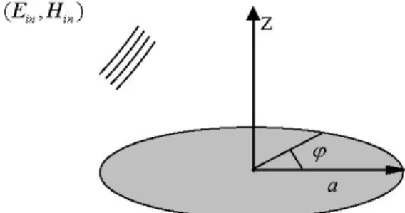
Figure1. Diskgeometry
The disk of the radius ais located in free space attheplane (z=0). We introduce the cylindrical coordinates (r,
P,z)
with the origin on the axis of symmetry of the disk and denote totalfieldas a sum of the fields scatteredby the disk and the incidentone:E=
ESC
+Ein,
H=Hsc +Hin(1)
1
Introduction
Theproblem ofelectromagneticfield scattering byathin disk has been interested in since long ago. This is explained by
many different applications of this canonical shape. Besides of traditional applications in the printed disk antennas with
PEC orER disks, thin dielectric disk is used as a simplified
model of the tree leave [1]. Still besides, thin few-micron-radius disks are met as resonators of semiconductor lasers with ultralow thresholds [2].Manymethods ofcomputational electromagnetics have been used in their
analysis,
starting from empirical methods and finishing with the method ofmoments (MoM) and finite difference time domain method (FDTD). However, the use of these methods leads to difficulties such as prohibitively large matrices and impossibility of estimation of the error of calculations. In contrast, by using the method of lEs with analytical regularization it ispossibletoescapethese difficulties.
2 Problem
statementWe consider the problem of diffraction of a given time-harmonic electromagneticfieldbyazero-thickness dielectric disk. Thegeometryof thisproblemis illustratedinFigure1.
The components of the scattered fieldmust satisfy the setof homogeneous Maxwell equations outside the disk, the 3-D
radiation condition, the condition of local integrability of
power (edge
condition),
and the generalized boundary conditions(see [3])onthe disksurface,at (z=0,r<a):-[E; +Etg =ZoR* nx[H -Htg],
(<L) -S.nx E+ -
Et-g
.Here, Z0 is the free-space impedance, and R and S arethe electric and magnetic resistivities. For a thin dielectric disk theyaregivenby
R=iZcot 8rirkT'
2 22/ )' S=-cot - 1 2Z 2 )'
Ir/'rI
>>1, T<<4
.(3)
8r/brI
>>1, 'T<<4
.(4)
ZOHt+g
+Ht-g
: 2Here, Z is the relative impedance of the disk material, k=co c is thewavenumber, Er is the relative permittivity,
P'r is therelative
conductivity,
20
is thewavelength
infreespace,and r is the thickness of the disk.
For athinelectricallyresistive (ER) disk they are given by
R= 1
Zoo-r S=o0.
(5)
For azero-thickness PECdisk theyare given by Escr
R=0, S =°o (6)
Z
OHs+c-
rOn the rest part oftheplane (z=0) the components of the
iZoHJc
vfieldarecontinuous. Here
Z Ox
inHC
= -o ee0
;mZ()llK)d(8)
where
e+,
(K) and h1+z(K) are the images of the normal tothe disk field components in the spectral domain. They are the unknown functions to be found. Thenthe tangentialtothe disk componentscan be written as follows:
°°m9 °°lYK
(KP)-/(K)r+
(K)) K 9Z e'm9*
|e±'
(K)4Hm(KP)
z(
dlc(10)
~~c
~~~~kae+,
(K)3 Basic equations
Weexpressthe scatteredfield components normal to the disk in terms of the azimuth-angle Fourier series and the radial
inverseintegral Hankeltransform:
E- = E elm"
e±lY()e±m
z(IC)Jml(icp)icdlc,
(7)m=-oc 0
Hm
(KvP)
= mJIm(IKp)/(,p) IJl (IKo)(1
1)
is the kernelmatrix function of the vector Hankel transform, p =rI
a,;
=z I a andy(K)=C(ka)2
K2.Onsubstituting (9) and (10) to (2) and continuity conditions outside the disk,we, ingeneral case, obtain the set of coupled DIEs for the four unknown functions in the spectral domain:
(O)~
Ko
K p)(i/(C)(l(rIc)+
e';'(
*')0,°o (K)) +2Rikaum(K)do -ka
(v,
(K)+e ( IV0' (K))-2Ry(K)v (K))(Kp)
ikaj
ujKK=
( )JHm
(Kp)
dlK = 0 K y-)(K)vZ(K))
yO i0V,i,j(K)(V,
(K)
+eP
V4'0
'(K))
+2Sikav,(K)
fHm
(Kp)ka
(u
(K)+
e (
)
°
IUrn'
(K))
+2S
I(K)u+
dlIc(
ikavm(K)
(° JHm(K) dl IoYY(K)0uZ+(K))
OHere u+(K) X v-m(K) are linear combination of original
unknownimage function:
um~(K) =(emZ (K)+_ em,z(K))12(14
(14)
vm(K)=(hm1z(K) hm7z(K))12
The obtained set of DIEs can be written in the following abstractform: JHm(Kp)*SI(ka,K,p)*X(K)dK 0 = |Hm(Kp)*S2(ka, Kc, p)*Xo(Kc) dlK 0 (15)
where S12(ka,K,
p)
are singular diagonal matrix-functionsoftwo variables with the singular point at infinity (K=
o0),
X(K) is the unknown vector-function, XO(K) is the given vector-function. Note that the singularity of S2(ka,K,p)
leadstothelimitation ofX0(K) intermsof the allowedclass
p<l, (12) p>1, p<l, (13) p>1, c/co>> I
of functions. To solve (15), we use themethod ofanalytical
regularization [4]. It consists of the following two parts: First, we split the function
SI
(ka,K,p) into the singular and regular parts:(16) S1(ka,K,p)=Z (ka,K,p) + P1(ka,K,p)
Then(15)canbe rewritten as follows:
0
|Hm
(Kvp)
* -1(ka,Kn,p)*X(Kc)
dlc=F(p,
X(...))0
where theright-handpartis
F(p,
X(.))
fHm
(Kp).
(-PI
(ka,
K,p)
*X(K)
+0
+S2 (ka,Kc,p)*X0
(Kc))
dlKThe solution of "canonical" IE is sought in the following
form:
X(2)
=Km
(2,
p)*F(p, X(...)) dp
(19)
0Now we substitute expression (18) into (19) and reduce the
coupled DIEs (15) to the following Fredholm IE of the
second kind:
Xm(2)-JiW(K)Xm
(K)Kl)
(K,A)dK+ika 2mAmIi)A-m
00 00
X(i)
+fKm
(,p)
fHm(Kp).
P1(ka,
K,p)* X(K)
dKdp
0 0
00 00
=
Km
(i,p)
fHm
(Kp)
*S2
(ka,
K,p)
*Xo(K)
dlKdp
0 0
(20)
Extraction of the singular part of integral operators in (12),
(13) leads to two different-type DIEs in the case of PEC (R= 0 and S=ox) and dielectric or ER disks. Finding the (17) solutions in both cases with (m.0) is based on decupling
(17)
theDIEsby the integrationin p and introduction of four (ingeneral case)constantsof integration. This procedure leads to
theDIEs,whichcanbecast tothe following short form:
(p<1), (18) (21) (p>1), {KU
U(-(K)-
f(K)}Jm (Kp)dK0= O |um(K)Jm(Kcp)dl =O 0Such DIEs can be solved analytically by using the Abel
integral transform and inverse Hankel integral transform in
the case of 8=+1 orjust inverse Hankel integraltransform
in the case of 8 =0 . Additional equations for finding the constants ofintegration follow from the conditions of local integrabilityofpowernearthe diskedge.
As an example, we show the final integral equation of the
Fredholm second kind (m . 0) in case when the diffraction
by thePECdisk is considered.
-1/2(A+
1)-'
m+3 (2)++i2m!Bm 1 (2+1) Jm 1/2(2) J
)i
K l(K)(K+1)2elY(K)|;°Ix'
(K)K()
(,A)dK 0Ym(2)
JW(2)Ym(K)2Y
'()Kim
(K,2)dK+2mAJA2 2)7-(2)(2++1)
J (2)+0
00
+2mfkaIBW..(i)(K)d
+1kamAIi) 2mB_I0~~~~~~~~~~~~~~~~~~
-JiW(K)Ym
(K)G(l
)'(K)dK
+ika2mAmIij)-i
2mBmI(
0
-
W(/C)ym
(1c)G(
1)
(1c)d1c+2mAmI,3)
-ka2mBmIm(4
Here Xm(A), Ym
(2)
arethe unknown functions, Am, Bm arethe unknown constants ofintegration,
Kj-l)
(K,A),Gmcj)
(K)arethekernelfunctions, w(K)istheweight function,
x5,
(A)(22) i(Kc+I)2ei
Ymc)4'
(,
(2A)dK
(2) =iK
)'y(K)(K
+1)2elr(K)I0 Ix
(K)G(1)
(K)dK0
') =-|i(K+1)2
eiY(K)0I4
0y
(K)Gm1)(K)dK 0and
yo
(2)
are the given functions determined by the4
Numerical results
The Fredholm second kind nature of the derived equations guarantees the existence of solutions of (22) and the
convergence of numericalalgorithm basedonanyreasonable
discretization scheme. For example, it can be a simple
projection scheme with the basis functions taken as the
so-calledstepfunctions:
(>I) Ee[s(n-1),sn)
To verify the obtained equations we calculate the main
characteristics inthe case of the PEC disk with the incident
fieldbeing the field ofa horizontal electrical dipole located onthe disk axis andorientedalongthe line
(p
=0).Theyarethe far-field radiation patterns and the total radiated power.
Besides, we calculate truncation and discretization errors in
thecomputation of thetotal radiatedpower.
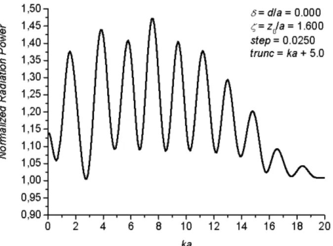
1,45- =z /a=1.600 0=~~~~~~~~~~~~~~~~~~~~~~~~~1,40- 1l^11step=0.0250 1,35 trunc=ka +k5.0 . 1,30
1(3
1,25-1,20 (U1,15-o1,10 1,05-1,00 0,95 0,0 2 4 6 11'2 1'4 1'6 1'8
2'0
kaFigure2a.Normalized radiationpowervs.thenormalized disk radius. ci) 0 cr_ 0 1,50 1,45 1,40 1,35 1,30 1,25 1,20 1,15 1,10 1,05 1,00 0,95 0,90 2 4 6 8 10 12 14 16 18 20 22 24 ka
Figure2b. Normalized radiationpower vs.the normalized
disk radius.
Figures 2a-2b show the normalized radiation power vs. the
frequency normalized by the disk radius.
Here;
is the normalized distance from the dipoletothe disk center, trunc is the truncation value of the domain ofintegration in (22) that is adapted to the frequency as ka+5. Figures 3a-3b show the relativecomputationerrorsgiven by:Errcurr = Pcurr-Pprev / Pprev (24)
where Pprev is the normalized total power at the previous computation point,
Pcurr
is the normalized totalpoweratthe current point. Figure 4 shows the dependence of P vs.;,
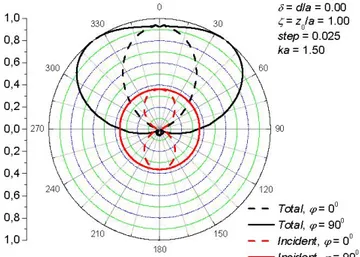
which is the normalized distance between disk and dipole. Figure 5 shows the far field radiation patterns for some
characteristic values ofparameters.
a kz LU (0a cIQ-0) 1-0,1 -0,01 a=dla=0.00 ;=zo/a=1.00 trunc=7.900 ka=2.9 , 312...5...I. ..5.... .0.,25 0,03 125 0,0625 0,1125 0,25 0...0,5 1 ...1 step
Figure3a.Discretizationerrorvs.thegridstep.
0,01563 0,00781 0,00391 S 0,00195 *
0,00098
!
LU 0,000490,00024
U 3(10 0 i* U 0,00012 0,0001|6 | 2 3 4 5 6 7 8 9 10 11 12 truncFigure 3b. The computationerror vs.the value of truncation of theintegration domain.
0 0= 0 0 CD _ CD -TCD m 2r 1,8 -1,6 -1,4 -1,2 - 1,0-0,8 -0,6 -0,4 -0,2 -8=dla=0.000 step=0.0250 ka=2.9 trunc=7.9
1 g~~~~e-~
/
2 3 4 5 6 7 8 =zola 0,0-iFigure4.Normalized radiationpower vs. the distance from the disktothedipole.
1,0 -0,8 -0,6- 300 0,4- 0,2-0,0-270 0,2- 0,4-0,6- 240 0,8 -1,0- 210 180 8=dla = 0.00 30 ;=z0/a= 1.00 step=0.025 ka=1.50 60 90 120 -- Total, v=00 - Total,9=900 150 - - Incident,C=0° Incident, 9=90° Figure 5b. Farfield radiation pattern ka=1.5.
10° -0,8 0,6 0,4 -0,2 0,0 270 0,2 0,4 0,6 0,8 1,0- 210 180 5=dla= 0.00 30 ;=zo/a 1.00 step=0.025 ka=1.00 60 90 120 -- Total C=00 - Total, C=900 150 - Incident, C= 0 Incident, (9=900
Figure5a. Farfield radiationpattern for ka=1.
1,0 -0,8 -0,6- 300 0,4- 0,2-0,0-270 0,2- 0,4-0,6- 240 0 0 ,8 ---1,O 210 150 180
Figure5c. Farfield radiationpattern ka==
S=dla=0.00 ;=zo/a=1.00 step=0.025 ka = 2.9 60 !90 120 -- Total,v=0° - Total, 9=900 -- Incident,9=00 Incident,9=900 2.9.
5
Acknowledgements
This work was supported by the National Academy of Sciences of Ukraine viaprojectPORIG #36/07H, the Turkish Council for Research in Science and Technology and the Royal Society,UKviajoint projects.
imperfect thin screens", J. Telecommunications and InformationTechnology,Warsaw: NITPress,2001,no3,
pp. 72-79.
References
[1] I.-S.Koh,K.Sarabandi,"Anewapproximate solution for scattering by thin dielectric disks ofarbitrary size and shape" , IEEE Trans Antennas Propag., vol 53, pp.
1920-1926,2005.
[2] X. Liu,W. Fang, Y. Huang, X. H. Wu, S. T.Ho, H. Cao, R. P. H. Chang, "Optically pumped ultraviolet microdisk laseron asilicon
substrate",
AppliedPhysicsLetters,vol. 84,No 14,pp.2488-2490,2004.[3] E. Bleszynski, M. Bleszynski, T. Jaroszewicz, "Surface-integral equations for electromagnetic scattering from impenetrable and penetrable sheets", IEEE Antennas Propag. Mag.,vol.35,pp. 14-24, 1993.
[4] A.I. Nosich, "Method ofanalytical regularization based
on the static part inversion in wave scattering by f -r r- -1 i --mo_ -I


