Modeling of
Subsonic Cavity Flows by Neural Networks*
Mehiiiet Onder Efet Marco Debiasii Hitay Ozbaya and Moliammad Samiinyn
Abstract-lnflueiiciriy the behavior of a flow field is a core issue as its imnprooement can yield significant increase of the efjiciency and performance of fluidic systems. On, tlie other hand, the tools of classical con- trol systems th.eonj are n.ot directly applicable to pro-
cesseg displaying spatial continuity as in fluid flows. The cavity flow is a good example of thi,s and a re-
cent research focus in aerospace scierice is its mod-
eling and control. Th,e objective ia to deoelop a fi- nite dimensional representati7ie model for the systerri with appropriately defined inputs and outputs. To-
wards the goal of reconstrr~cti7iy the pressure fluctaa- tions measured at the couity floor> this paper demon- strates that giiien some history of
i n p t s
and outputs,a nenral network based feedfornard model can be de- veloped such, that the responxe of the neural network
matches the measured response. The aduantayes of ,tising such a niodel are the representational simplic- ity of the model, s t r ~ x t u m l flexibilitg to enable con- troller design and the ability to store inJonnation in an interconnected ,stmcture.
1
Introduction
Tlie fundamental objective of aerodynamic flow con- trol is to develop stratcgics to excit,e thc flaw field so that a desired behavior is observed or some unde- sired phenomena are eliminated. Reducing the skin friction on the body of an aircraft constitutes a good example of control that results in reduced drag and thus reduced fuel consumption. Another example is the reductiou of undesired high-level pressure fluctu- ations in a modern aircraft weapon hay: which cause material fatigue and damage to stores. The latter
phenorncnon is known as ciLvit,y flow [l] and repre- sents a good study benchnisrk due to the dyimrni- cal richness of its flow physics while its relevance to the above mcritioiied applications makes it an appeal- ing snbject for investigation. Tlie challenges faced in controlling these flow systems clearly stipii1al;e the de- velopment of well-interactiiig control media sucli that the exist,irig literature is expanded as well as new a y plication domains axe initiated.
The control of acrodynamic flows has t,radition- ally been accornplished by using passive t,echniques, and recently open loop strategies [2], which lack the advantages of feedback control schemes. More r e cents efforts have closed the loop based on ad hoc and trial and error type schenms, 13; 4, 5 ;
GI.
To make the approach more general, the loop must be closed based on flow models, which i s a challenge due to t,he flow systems' infinite dimeusionality, t,he complcx- ity introduced by Navier-Stokes equations, the mea- surcrnent difficulties and the dynamics introduced by measurement and actuation devices. Extensive work have been dons in the modeling of aerodynamic flows, [7; 81. The Proper Orthogonal Decomposition (POD) has constituted a widely used method for model de- velopment yet t,he POD based models have revealed convcrgerice and/or drift, problems in t,hc behavior of temporal variables. Another approach is to ex- ploit the physics of the problem. R.owley et al. and Williams ct al. focused on this from a linear syst,ems point of view, [4; 9, 101. The acoustic waves produced by the shear-layer scatteririg at the downstream wall of the cavity reach, after some propagation delay time: the inconling flow in the receptivity region (i.e. the cavity upstream wall) and a delay-based coupled dvnamics arise. The eked studies demonstrate that 'This work was sulwo'ted in Part by AFRLIV.4 aridAFOSR under contract no F33615-01-2-3154.
tcorrasponding Author,, Alilim University, Department of
Mechatrorlio Engineering, Inrek, GGlbql. ~ ~ - 0 f i 8 3 , j ~ ~ h ~ , Turkey, E-mail: anderefeOieee.org, Phone: +00-312-586-8358,
tile shear layer dcvelopment: acoustic scat,tering, cav- ity acoustics and receptivity can be represented dy- namically as transfer functions. It must be noted t h a t tlie parameters of the devised transfer function are Fax: +90-312-586-8091
University, Columbus OH 43210, U.S.A.
Bilkent University, Bilkent: TR.06800, A n h r a , l'lrkey; on leave from Department of Electrical Engineering, The Ohio
State University, Columbus, OH 43210, U.S.A., E-mail: oahayOee.eng.ohirrstate.edu
tuned such that the frequency content of the experi- mental data obt,ained matches the frcquency response $Department of Mechanical Engineering, The Ohio State
§Department of Electrical and Electronics Engincering, Of the For the i n
14,
g: lo]:Yuan et al. [6] demonstrate the design and imple- "lentation of a
xm
A very good review of flow control literat~ure is presented by Cattafesta TDepartment of Mechanical ~ ~ , ~ i~h~ ~ Ohio , ~state
~ ~ iet al., [Ill: ~ ~ , in which the techniqnes and the advances are summarized from both a fluid mechanical point University, Columbus OH 43210, U.S.A.of view and a control specialist's point of vicw, and a tabulated cornparison of operating conditions and ob- tained results is presented. A common starting point in all flow control applications is to describe t,he dy- namics in terms of the inathematical tools, i.c. to devise a niodel capturing thc cssential dynamics. In t,his paper, the emphasis is on the reconstruction of tlic pressurc measured from a particular locat,ion in tlie cavit,y based on the past observat,ious from the same location and the excitation values.
Thc research carried out at Collaborat,ive Center of Control Science at The Ohio St,ate University has yielded a well-dcsigned experiniental facility. which provides an cxcelleni plat,form for data acquisition a,nd cxploririg the physics of flow plicnomena and ban- dliiig the control problem. The experimental setup, which is located at ttic Gas Dynamics and Turhuleiicc Laboratory, is a sniall wind tunriel that provides con- tinuous subsonic flow from very low speed to Mach 1 with a rich parameter space suitable for fccdback control developnicut,. A shallow cavity with length to depth aspect rat,io L I D = 4 is recessed in the floor of the tcst section. The control is providcd by a syn- thetic jet exhausting from a slot spanning the width of the cavity upstream wall. For a detailed iiifor- niat,ion describing the simulations and expcriniental work on the cavity setup, thc reader is rcferred to the past work of the aut,hors in [12, 131.
Figiirc 2:
A
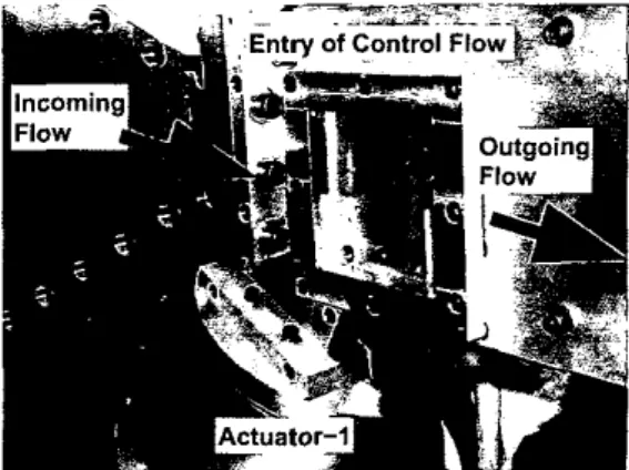
closer look at the tcst sectionFigure 1: A general vicw of the experiniciital facility.
In Figure 1, tlie test section and it,s peripherals arc shown. The incoming flow is directcd towards the test section through a converging nozzlc and leavcs tlic t,est section by passing through an exhaust tube. A closer look at t.he test section setup is given in Figure 2, i n which the entry slot of tile control jet is visiblc at the receptivity region. The physics of the process should now he more clear. The input to the system is the signal applicd t o the actuator ( ~ ( t ) ) , and thc output is the pressure measured at
ulite transducer that
Figure 3: A closer look at the cavit,y floor
the bottom of t.be cavity
( ~ ( t ) ) .
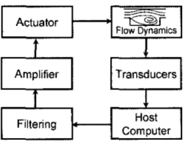
The Kulite dynamic pressurc transducer located at the center of tlie cav- ity floor and used to obscrve the system can bc seen in Figure 3. Thc saiiie figure provides also a bett,er vicw of the cntry slot of the control How as wcll as an appreciation of the cavity geometry. The cavity floor Kulite, as well as othcrs at selectcd locations of the cavity domain, are connected to a Nation1 Instrnrnent data acquisition system hosted in a computer. In Fig- ure 4: we illustrate a complete view of the cavity flow identification and control system. The contributionof this paper is to eniphasize that the use of neural networks can offcr promisingly Hexible and accurate solutions.
This paper is organizcd as follows. The sccond section describes the nenroidcntifier, the training al- gorithm, and the niotivating factors. The identifi- cation results and specific implenientation issucs are
P
Amplifier Transducers
rH-1
Computer Filtering
Figure 4: A complete view of the flow identification arid control loop.
discussed in the third section. The conclusions are presented at t h e end of t,he paper.
2
Neural Model
In flow control applications, several factors encour- age the use of neural networks. First of all; the process dynamics are quite complicated. Strong in- terdependencies between the vsriables involved make it challenging to come up with a compact and use- ful representative model as shown by Saminiy et al. [12: 131. Secondly, the system and its peripherals could be modeled individually, which is an inevitable stage in [6: 4, 91. Finally. the data contains measure ment noise. From this point of view, one sees that the neurocomputing algorithms and their connection- ist niodels are excellent candidates for building a dy- namical model containing the effects of process sub- systems, which are the process it,self, scnsora, actua- tor and the filter(s) collectively. It is clear that the conditions above force the use of a model st,ructure that is able t o generalize the data while improving the information content progressively. A good deal of information about neural networks can be found in [14, 151 and the references therein.
An important issue in using neural networks is the parameter adjustment strategy. In the literature: niany alternatives are proposed but the Levenberg- Marquartdt technique is widely accepted as one of the most powerful ones. The algorithm is an ap- proxima1,ion t o the Newton's method, aud both of them have been designed t o solve the nonlinear least squares problem [15, 161. Consider a neural net- work having single output, and N adjustable pa- rameters (weights and biases) denoted by the vector LJ, := ( W I , ~ W ~ , ~ . . . :UN,); where a subscript p de- notes the observation instant. If there are P patterns
in the ensemble, over which the interpolation is t o be performed, a cost function qualifying the perfor- niance of the interpolation can be defined as
-
p = lwhere d, and x p are the desired and observed re- sponses at index p . respectively. It should be noted that xp is a function of g,,. The paranleter update law based on Levenberg-Marquardt optimization is perfornied as
%+I = gk - ( P I N X N
+
J(&?k)TJ(&k))-l xJ ( d d W k ) , (2)
> B w z ; : .
. .
e)
with e&,) := cl,-where J is the Jacobian: whose pth row is composed x p ( t p ) . After a suitable iniplenientation of t,he train- ing algorithm, one can come up with a niodcl having the structure
& (w ) 0 4 % 1 %(E 1 of
(
Z k + l = f ( ~ k r 2 k - 1 :
. . . ,
Zk-n,? l k : U k - 1 , .
. .
; U k - m ) , (3)where the delay depths n and
m
are user specified parameters. T h e process of learning refines the func- tion f and the resulting connectionist structure can rebuild the flow meawrements so that the quantity in (1) is minimized over the set of P training pairs.3
Identification of the
Flow
The identification mechanism of a flow system by a neural network is depicted in Figure 5 : whero the ncu- ral network is forced to imitate the response of the system under the same operating conditions. T h e training algorithm refines the input-output descrip- tion of the neural identifier so that the estimation error is minimized over a set of representative input- output data.
Training
Parameter
update SpWB
The first stage of the identification process is to collect t,lie data. For this purpose, we initially fo- cus our attent,ion to a Mach 0.3 flow. We acquired two extensive sets of data from the pressure transduc- ers in the test section by sampling the corresponding amplified and anti-aliasing filtered signals at a rate of 200 kHz. Thc actuator cxt:it,ation signal was high- pass filtered to stop any spect,ral content below 1 kHz which would damage the actuator. Of t,he two sets of data collectcd, one is used for training while the other is used to validate the model. For this pur- pose, the training data set has been acquired when a
2 kHz sinusoidal excitation voltagc of 4V7,n. is sent
to the actuation device. The pressure is read from tlie Kulite transducer seen in Figure 3. During the modeling t,rials, we have chosen a fecdforward neu- ral network with a single hidden layer. The neurons in the bidden layer contain the hyperbolic tangent nonlinearity and the output neurons are chosen to be linear. The input vector to Ihe neiiroidcntifier is composed of [ u , s : u $ l l , a s : z s ~ l , n : k - n ] , i.e. n = 2 and m = 1, and the rcsponse of the network to this vector is ~ s + ~ . Fiirt.hcrmore, we have used 12 hid- den neurons lettirig us end up with 5-12-1 configu- ration. With the Levcnberg-Marquardt scheme: the entire d a h set, which contains 16381 pairss? passed through t~he neural network 50 times (epoclies) while modifying the weights and biases according to (2). At. t,hc end of this proccss, t,lie Mean Squared Error (MSE) has decreascd below 8.85e-6.
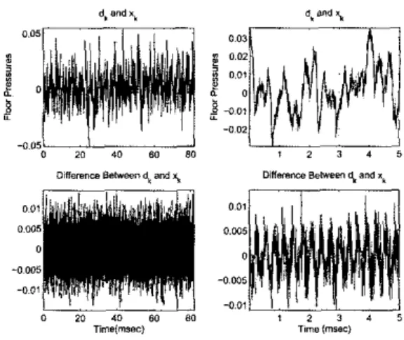
The tests have been carried out with another sinusoidal iiipnt signal with amplitude 4V and fre- quency 3.25 kHz, and the output from the process and the response of the neural network have been recorded. According to the acquired data, the results scen in Figure 6 and 7 have been obtained.
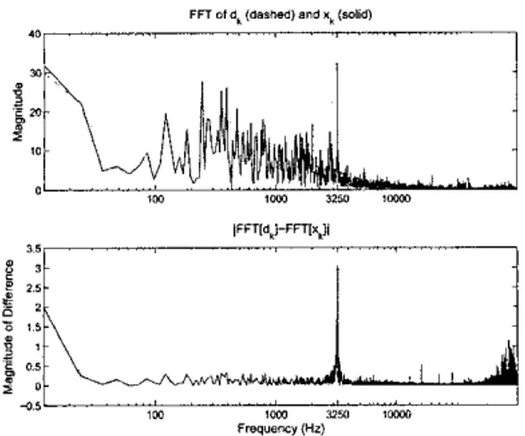
According to the results illustrated in the top row of Figure 6: the two curves are almost indistin- guishable. The discrepancy curve shown i n the bot- tom row confirms the accurate reconstruction claim of the paper. Tlrc coinparison in the frequency do- main is presented in Figure 7: where the two curves are similar cnough to use the devised niodel as a dy- namical representative. A look at the error niagni- tude in the bottom row of Figure 7 emphasizes the reconstruction accuracy of t,he neuroideutifier. It is visible that the error curve has a reasonably small magnitude ovcr a wide range of frequencies.
It should be noted that the topology of the neural nctwork aiid the type of nonlincarities absolutely de- pend upon the designer's perceptions, intuitions and experience. There is not an analytical way to de- termine thc number of hidden layers as well as the nuniber of neurons. Based on our exteusive work, the simplest configuration yielding a satisfactorily precise respousc is the one presented here.
d. and xl 6. *"d
,
i
I) 20 40 50 ell , 2 3 4 5
Timslmrsc) T,rnB(rnSBS)
Figure 6: Top row: The data obtained from the Kulite transducer (&) and the response of the neu- roidentifier (21). Bottom row: The estimat.ion error:
dk
-
3 . k . The plots on the left are for the entire testset wliile the plots on the right are only for the first 1000 samples i.e. 5 111s time.
A last issue th at should bc discussed is a com- parison of the findings with those appeared in the literature before.
a) POD is computationally intcnsive, vulnera- ble to small nunierical irnprecisiori and the iiiodcls may exhibit progressively increasing drift and/or in- stability. Aside from all thcse, POD models for flow prohlenis arc generally very complicated. Another difficulty of POD based flow niodels is the proccss of spatial separation of the control entry. The ad- vantage, on the ot,her hand, is that, once it works, the model is global over the entire cavity domain and the individual pcrformance inetrics can be distributed over the physical geoniet,ry of the cavity.
b) Delay based models as st,udicd in [8, 4; 9, 101 are very useful in terms of designing controllers, [6], yet, it is difficult to inject the dynamical properties of sensors, actuators, arid filters in a collective manner. The match in frequency domain can be achieved to some extent but, the time domain match is not as good as the onc we present here. The advantage of using these models is the possibility of using the tools of linear control systcms theory.
c) Neural nctwork based identification scheme is superior to the ones mentioned above in t,he sense that it is based on the data containing the effects of systcni components collectively. The designer can decide on the topology of t,he network as well i\s the training scheme to update tlie parameters. The trained network can be used for feedback controller design, 1171.
A I
303 laa uw ,mn
Fmqvensy (HI
Figure 7: Top row depicts the FFT magnitude pic- tures of thc desired ( d t ) and the estirnatcd (zk)
signals. The bottom plot illustrates the quantity IFFT(dt) - F F T ( z t ) / .
4
Conclusions
In t,his paper, identification of cavity flow system is studied. A neural network is used to imitate the behavior of the process under investigation. Several past values of the output and the input arc fed t o the neuroidentifier and the likely next, output is cstiniated accurately. This is done by suitably tuning the adjustable parameters of the neural network by utilizing the Levenberg-Marquardt optimization technique. The results are quite promising for devising a feedback control scheme t o manage the behavior of the flow field.
[2] Gad-el-Hak, h4.> Flow Contml
-
Passive, Ac- tive, and Reactive Flow Management: Curl-bridge University Press, New York, NY, 2000. [3] Cattafesta, L.N. 111; Garg, S.: Choudhari, M.;
and Liz F.; "Active Control of Flow-Induced Cavity Resonance,"
U.S.A.
1997 (Paper: AIAA-97-1804).
[4] Williams D.R.: Rowlcy C.W., Colonius; T., Mur- ray; R.M.; IVIacMartin, D.G.: Fahris, D.: Albert- son, d . , "Model Based Control of Cavity Oscilla- t,ions Part I: Experiments," 40th Aerospace Sci- ences Meeting, Reno, NV1 U.S.A., 200" (Paper: AIAA2002-0971).
151 Debiasi, 14. and Samimy. M., "An Experimental Study of the Cavity Flow for Close-Loop Flow Control," 33rd AIAA Fluid Dynamics Confer- ence and Exhibits; June 23-26; Orlando, Florida,
[61
171
181
191 A c k n o w l e d g m e n t s
This work was supporkd in part by the AFRL/VA and AFOSR through the Collaborative Center of Control Science at the Ohio State Univer- sity (Contract F33615-01-2-3154).
The authors would like to thank Dr. J.H. Myatt, Dr. J . DeBonis, Dr. R.C. Camphouse, X. Yuan, E. Caraballo and
P.
Yan for fruitful discussions in devising the presented work.P O I
Ill1
References
[l] Rossit.er, J.E.: "Wind Tunnel Experiments on the Flow Over Rectangular Cavities at Subsonic and Transonic Speeds," RAE Tech. Rep. 64037, 1964, and Aeronautical Research Council Re- ports and Memoranda No. 3438, 0ct.ober 1964.
[12] Samimy, M.: Dehiasi, M., Caraballo, E.: Ozbay, H., Efe,
M.
0.; Yuan, X.: DeBonis: J.; and My- att, J.H., "Closed-Loop Active Flow Control - A U.S.A., 2003 (Paper: AIAA2003-4003).Yuan; X., Efe: M O . , and Ozbay, H., "On Delay-Based Linear Models and Robust Control of Cavity Flows," presentcd at the NSF-CNRS Workshop on Advances in Time Delay Systems, Jan. 22-24, France, 2003.
Ravindran S.S., "A Reduced Order Approach for Optimal Control of Fluids Using Proper Or- thogonal Decomposition," Int. J . for Numer<cal Methods in, Fluids, v.34, pp.425-488, 2000.
Rowley, C.W.; Modeling, Simulation and Con-
trol of Cavity Flow Oscillations, P1i.D. The-
sis: California Institute of Technology, Pasadena, U.S.A., 2001.
Rowley, C.W., Williams, D.R.; Colonius, T., Murray, R.M., MacMartin, D.G., Fahris; D.; "Model Based Control of Cavity Oscillations Part 11: System Identification and Analysis," 40th Aerospace Sciences Meeting, Reno: NV, U.S.A., 2002, (Paper: AIAA2002-0972). Rowley, C.W., Colonius, T., Murray, R.M., "Dy- namical Models for Cont.ro1 of Cavity Oscilla- tions:" 7th AIAAjCEAS Aeroacoust.ics Conf., May 28-30, Maastricht, T h e Netherlands, 2001, (Paper: AIAA2001-2126)
Cattafesta, L., Williams, D., Rowley, C.W. and Alvi, F . , "Review of Active Control of Flow-Induced Cavity Resonance?" 33rd AIAA Fluid Dynamics Conference and Exhibits, June 23-26, Orlando, Florida, U.S.A., 2003 (Paper: AIAA2003-3567).
Collaborative Approach:" 41st AIAA Aerospace Sciences Meeting and Exhibit, Jan. 6-9, Reno, Nevada, U.S.A., 2003 (Paper: AIAA2003-0058). [13] Samimy. M., Debiasi, M., Caraballo: E., &bay,
H., Efe,
M.
O., Yuan, X.; Myatt, J.H. and DeBonis,J.:
"Development of Closed-Loop Ac- tive Flow Control Based on Low Dimensional Model," 33rd AIAA Fluid Dynamics Confer- ence and Exhibit.s, June 23-26, Orlando, Florida, U.S.A., 2003 (Paper: AIAA2003-4258).[14] Jang, J.-S.R., Sun, C.-T., Mizutani, E., N e t m -
P u z y and
Soft
Computing, P T R Prentice-Hall,1997.
[15] Haykin,
S.,
Neural Networks: Macmillan CollegePrinting Company, New Jersey. 1994.
[lG]
Hagan,M.T.
and Menhaj, MB., "Training Feed- forward Networks with the Marquardt Algo- rithm"; IEEE Trans. on Neural N e t w d s s , v.5,No. 6; pp. 989-993: November 1994.
[17] Narendra, K.S. and Part,hasarathy. K., "Identifi- cation and Control of Dynamical Systems Using Neural Networks", IEEE Trans. on Neural Net- works, v.1, No. 1> pp. 4-27: 1990.