Quantum Dot/Light-Emitting Electrochemical Cell Hybrid Device and
Mechanism of Its Operation
Julia Frohleiks,
†,2Svenja Wepfer,
†,2Yusuf Kelestemur,
3Hilmi Volkan Demir,
3,4Gerd Bacher,
2and Ekaterina Nannen
*
,†,2†Research Group“Solid State Lighting”, NanoEnergieTechnikZentrum, University Duisburg-Essen, 47057 Duisburg, Germany 2
Werkstoffe der Elektrotechnik and CENIDE, University Duisburg-Essen, 47057 Duisburg, Germany
3
Department of Electrical and Electronics Engineering, Department of Physics, UNAM−Institute of Materials Science and Nanotechnology, Bilkent University, Ankara 06800, Turkey
4
Luminous! Center of Excellence for Semiconductor Lighting and Displays, School of Electrical and Electronic Engineering, School of Physical and Materials Sciences, School of Materials Science and Nanotechnology, Nanyang Technological University, Singapore 639798, Singapore
*
S Supporting InformationABSTRACT: A new type of light-emitting hybrid device based on colloidal quantum dots (QDs) and an ionic transition metal complex (iTMC) light-emitting electrochemical cell (LEC) is introduced. The developed hybrid devices show light emission from both active layers, which are combined in a stacked geometry. Time-resolved photoluminescence experiments indicate that the emission is controlled by direct charge injection into both the iTMC and the QD layer. The turn-on time (time to reach 1 cd/m2) at
constant voltage operation is significantly reduced from 8 min in the case of the reference LEC down to subsecond in the case of the hybrid device. Furthermore, luminance and efficiency of the hybrid device are enhanced compared to reference LEC directly after
device turn-on by a factor of 400 and 650, respectively. We attribute these improvements to an increased electron injection efficiency into the iTMC directly after device turn-on.
KEYWORDS: quantum dots, light-emitting electrochemical cell, iTMC, LEC, hybrid device, electron injection, Förster resonant energy transfer
■
INTRODUCTIONLight-emitting electrochemical cells (LECs)1−4 represent a promising large-area device concept, besides organic (OLED)5,6 and quantum dot (QD)-based light emitters (QLEDs).6−9The main difference to OLEDs is that the active layer comprises ionic components in addition to the light-emitting species (polymers or transition metal complexes). These ionic species start moving under applied voltage and thereby facilitate charge injection into the light-emitting component. This property makes LECs very attractive since the multiple charge injection and transport layers, which are obligatory in OLEDs and QLEDs, can be omitted, whereby the whole layer stack is simplified (even down to a single layer). In addition, air-stable electrode materials can be implemented, thickness variations of the active layer can be tolerated, and easy solution-based fabrication procedures can be established.1,2,10 These properties make LECs attractive candidates for future lighting applications. Although the exact operation mechanism of the LECs is still under debate, two different models, the electrochemical doping model (ECD)11 and electrodynamic model (ED)12were proposed. Recently, a unifying model was
demonstrated, showing that the ECD and ED models are both valid in LECs as limiting cases depending, for example, on the injection properties of the contacts.13
Since the charge carrier injection and transport in this type of devices is initiated by the movement of the ionic species, the response and turn-on time of LECs is comparatively long, ranging typically from subseconds to hours, depending on the ionic conductivity of the light-emitting layer.1,14 Therefore, these devices are believed to be more applicable in lighting technology rather than high-end displays. On the basis of the active light-emitting material, two different classes of LECs can be defined: polymer LECs (p-LECs) or ionic transition metal complex LECs (iTMC-LECs). iTMC-LECs are able to harvest both singlet and triplet excitons and thus allow for intrinsically higher quantum efficiencies than fluorescent p-LECs.10,15,16 Also, iTMC-LECs show typically higher brightness above 1000 cd/m2,17,18while p-LECs remain quite often in the range of 100
Received: June 7, 2016 Accepted: August 24, 2016 Published: August 24, 2016
www.acsami.org
Downloaded via BILKENT UNIV on December 23, 2018 at 18:10:47 (UTC).
cd/m2at similar lifetimes.19,20On the other hand, iTMC-LECs frequently show turn-on times in the order of hours, while pLECs typically turn-on within a second.10,20−23Nevertheless, the turn-on time of the iTMC-LEC can be significantly reduced by the addition of an ionic liquid to the active layer,24,25as well as by implementing a current driving mode of the device.26
Despite the potential benefits of the iTMC-LECs as well as recent advances,1the market entry of these types of devices is challenging mainly due to the lack of at the same time efficient, bright, and long-term stable emitter materials of different colors, particularly of red27,28and blue29,30emitters, resulting in challenges in the realization of white emission.1,31,32Especially high brightness and long operation lifetime seem to be hard to unite: most devices with high brightness are short-lived and vice versa.16,27,29On the other hand, the discovery of stable, yellow iTMC-complex due to intramolecular π−π stacking inter-actions33 and pulsed operation mode yielded devices with lifetimes exceeding 4000 h at maximum luminance over 650 cd/m2and subsecond turn-on times.17Recently, the approach of multiple π-stacking interactions yielded promising results also for red-emitting complexes,18 making the iTMC-LECs together with their simple architecture very attractive for industrial roll-to-roll fabrication.1,34
Combining the stability of semiconducting materials with their solution-based properties, colloidal QDs offer an alternative approach for large area lighting concepts thanks to their high color purity which is tunable over a broad spectral range by tailoring their size, shape, and composition.7Typically, QDs are adapted in OLED-like structures, containing several carrier injection and transport layers. Recently these QLEDs were presented with highly promising performances for device application including luminance levels above 200.000 cd/m2
and efficiencies greater than 18%.8,9,35 In the case of iTMC-LECs, as discussed above, the variation of emission color turned out to be challenging, so that the use of QDs could fulfill that need. The incorporation of QDs in p-LECs is rarely studied yet,36while the implementation of QDs in iTMC-LECs was not reported so far.
■
RESULTS AND DISCUSSIONHere we present a novel concept combining QDs and iTMCs in a hybrid device (QLEC) by adding an additional QD layer prior to the cathode to the conventional iTMC LEC architecture. In contrast to mixing concepts as suggested for p-LECs by Norell Bader et al.36and for pure QDs by Qian et al.,37 we expect light emission from QDs and from iTMCs which is not dominated by energy transfer excitation (e.g., Förster transfer) but rather by direct charge injection into both active layers. In this case, the iTMC layer can be expected to act as a hole injection and transport layer for the QDs8 and vice versa; the QD layer may improve electron injection into the iTMC. Thus, an increase of luminance and a decrease of turn-on time can be achieved with improved device efficiency. Therefore, this device concept can potentially improve two critical issues of iTMC-LEC, performance and emission color, simultaneously.
Figure 1a shows the device concept for the QD-iTMC-LEC hybrid schematically. CdSe/CdS core−shell QDs with average size of 7 nm (see TEM image inFigure 1b) complement the conventional iTMC-LEC layout in form of an additional spin-coated layer placed on top of the active LEC layer. The simplified energy level diagram for the hybrid device is shown inFigure 1c. The values for ITO, PEDOT:PSS, QDs, and Al were taken from the literature.8,38The positions of the highest occupied/lowest unoccupied molecular orbitals (HOMO/ LUMO) of the iTMC were estimated by cyclic voltammetry to be about −5.9 eV/−3.3 eV. In addition to QLEC, conventional QLED and LEC reference devices (see Figure 1d under UV illumination) were also fabricated via a spin-coating procedure under ambient air conditions (see Experimental Section for more information on device fabrication). As can be seen in the pictures in Figure 1d, the layer morphology of the QLEC is not yet fully optimized, as the iTMC layer probably gets affected by spin-coating the QDs from toluene dispersion on top.
Figure 1e shows normalized photoluminescence (PL) spectra (dashed lines) of the active light-emitting layers of QLED (red), LEC (green), and QLEC (black). The LEC (iTMC) and QLEC (iTMC + 30 nm QD layer on top) active layers were measured in device configuration. In order to exclude a
Figure 1.(a) Schematic of the QLEC device design. (b) TEM image of CdSe/CdS core−shell QDs. (c) Schematic of simplified energy level diagram for QLEC. (d) Schematic of the device (top view) and photograph of processed iTMC-LEC, QLEC, and QLED devices under UV light excitation. (e) Normalized photoluminescence (PL, dashed lines) of the iTMC-LEC (green), QD layer (red), and QLEC-layer stack (black), and normalized electroluminescence (EL, solid lines) of the LEC (green) and QLED (red) reference devices at 5 V.
contribution of TPD to the total PL signal, the emission of the QD layer was measured on a reference structure comprising ITO substrate and a 30 nm thick QD layer on top, spin-coated in the same way as in the case of the QLED. The layers were excited by a diode laser (Picoquant PDL 800-D) at a wavelength of 405 nm and 17 μW power, and the resulting PL signal was analyzed by a combination of a spectrometer (Horiba Jobin Yvon iHR320) and a nitrogen-cooled CCD detector (Horiba Jobin Yvon Symphony). The QDs exhibit typical narrow peak emission at 620 nm with full width at half-maximum (fwhm) of 30 nm. The iTMC shows broad PL (fwhm = 96 nm) centered at a wavelength of 554 nm, which is typical for iTMCs emitters based on charge transfer transitions.39Unlike recently shown for hybrid devices based on iTMC and a conjugated polymer,40our hybrid devices show a pronounced superposition of iTMC- and QD-PL spectra with a dominating QD-PL peak at 620 nm. It should be noted that no energy shift occurs in the PL of the hybrid device compared to the single components.
The electroluminescence (EL) of the reference QLED and LEC devices, shown normalized inFigure 1e as solid lines, was measured by the identical setup as for the PL measurements. EL remains in both cases stable during the device operation and does not shift with applied voltage. Though, both reference devices show a small shift of the EL emission compared to the PL signal of the light-emitting material. The small red shift of 2 nm in case of QLEDs, typically observed in literature, can be attributed to the presence of strong electric fields during operation,41 local heating,42 and/or smaller charge-injection barriers into larger crystals.43 In the case of the LEC, a significant red shift of 22 nm was observed. This behavior is also typical for iTMC-emitters and can be attributed to optical and electrical carrier excitation, respectively.39,44
The EL emission characteristics of the hybrid device are shown in Figure 2. As can be seen from both (a) the color
images of the active light-emitting pad and (b) the corresponding normalized EL spectra, the emission color of the QLEC changes significantly with applied voltage.
For an applied voltage in the range of 2.5−3 V, the EL spectrum corresponds to the QLED EL and the device shows large area red emission. In this voltage regime, the device seems to operate like a QLED with active, light-emitting QDs and an
LEC layer acting as a hole injection/transport layer. With increasing applied voltage, the iTMC contribution is raised which becomes apparent first by a broadening of the EL spectrum toward the yellow spectral region and then by a shift toward higher energies (lower wavelengths). At a voltage of 5 V, the EL spectrum isfinally dominated by the iTMC emission. The corresponding position of the emission in the Commission International de l’Eclairage (CIE) 1931 color space was calculated from the EL spectra by ColorCalculator software provided by OSRAM. The variation in CIE-coordinates shown inFigure 2c illustrates the change in emission color for the low voltage range. In this diagram, the QLEC EL spectrum at different applied voltages is represented by dots and the EL spectra of the reference LEC and QLED devices by opened triangles, respectively. The color gradually varies from pure QD emission to iTMC emission. For voltages higher than 5 V, the devices gain in luminance due to increasing iTMC emission (seeFigure 2a) and show a pure iTMC-EL spectrum. At high voltage and luminance levels, we observe a degradation of the iTMC, which leads to a slightly broadened and red-shifted spectrum at 9 V.
For this hybrid device structure based on QDs and iTMC as light-emitting materials, an investigation of the physical nature of electroluminescence is of interest. As usually proposed for QLEDs,45−47 the direct injection of transported carriers into the QDs with following exciton formation and radiative recombination of holes and electrons in the QDs is one possible EL process. The second mechanism47−51that might be involved is a nonradiative energy transfer processes called Förster resonant energy transfer (FRET) which is based on dipole−dipole-coupling of donor and acceptor molecules.52,53 In this case, excitons are initially formed on the donor molecules (in our case the iTMC) and they are subsequently transferred to the acceptor molecules (here QDs). With lighting applications in prospect, direct charge injection into QDs would allow for a possible expansion of this architecture toward white light generation by implementation of blue QDs instead of red ones.
The main preconditions for FRET from donors to acceptors are the spectral overlap of the emission spectrum of the donor molecule with the absorption spectrum of the acceptor and the close proximity of the acceptor molecule to the donor molecule. The first precondition is fulfilled, as evident from Figure 3a, showing the spectral overlap between the iTMC emission spectrum with the QD absorption spectrum.
Further experimental investigation of the impact of FRET in hybrid organic and inorganic devices can be done by time-resolved photoluminescence spectroscopy.50,54In the case of an efficient FRET, the radiative decay times of the donor and acceptor materials (e.g., iTMC and QDs) in hybrid architecture should show a significant difference from the single emitter materials in absence of each other.53InFigure 3b, time-resolved PL measurements for QDs (detection at peak wavelength of 620 nm), iTMC (detection at peak wavelength of 554 nm), and QLEC (detection at 620 and 554 nm) in device geometry are shown. Within the experimental error, the time constants in the hybrid device geometry are comparable to the decay times found for the single reference layers (920 ns for iTMC, 6.9 and 19 ns for the QDs, respectively). Most important, the decay times of iTMC measured at 554 nm are found to be the same for the LEC and the QLEC device, clearly indicating that FRET can be neglected. It is also important to note that the
Figure 2. (a) Images of the active light-emitting pad at different voltages, (b) corresponding normalized EL spectra, and (c) calculated position of the emission color in the CIE 1931 color space. ACS Applied Materials & Interfaces
elongation of the decay times for QDs measured at 620 nm results from afinite spectral overlap with the iTMC emission. To study the performance of the hybrid device in comparison with the reference LEC and QLED devices, the voltage dependent luminance behavior was monitored for all three types of devices (Figure 4). While the QLED and LEC
reference devices show maximal luminance of 342 cd/m2and 548 cd/m2 respectively, at 8 V with a tendency of further
increase at elevated voltages, the QLEC reaches its maximum luminance of 385 cd/m2at 7.7 V followed by a slow decrease of
the luminance at elevated voltages, reaching 335 cd/m2at 8 V. Nevertheless, the QLEC exhibits a higher luminance compared to the LEC reference over a wide range of operating voltages. More important, the additional QD layer has a significant impact on the turn-on voltage of the device. The reference LEC device shows a turn-on voltage of approximately 4 V, whereas the QLEC starts emitting light below 2 V. The reduction in turn-on voltage can be attributed to pure QD emission in this low-voltage regime with the iTMC layer apparently working as a hole injection and transport layer. The QLEC starts light emission with an EL spectrum which is governed by QD emission at a voltage where the LEC reference does not emit any light at all. This excludes color conversion as a possible
mechanism for light generation and gives further confirmation of direct charge injection. It should be admitted that the injection and transport of holes by the iTMC layer into the QDs in the hybrid device is obviously less efficient than in case of the poly-TPD layer: the reference QLED has a turn-on voltage of 1.5 V in agreement with state of the art red QLEDs8,47and shows more than 1 order of magnitude higher luminance in the low-voltage regime compared to the QLEC.
At voltages above 3.5 V, the contribution of the iTMC emission to the total emission of the QLEC becomes progressively prominent and is even several orders of magnitude higher than the iTMC emission from the reference LEC in the range between 3.5 and 6 V. One of the reasons for this behavior might be an improved electron injection into the iTMC layer by the QD layer. In case of LECs, an improved charge carrier injection would result in a faster buildup of the doped regions, resulting in a faster turn-on of the devices. Thus, the performances of the LEC and QLEC were studied as a function of time to verify this assumption.
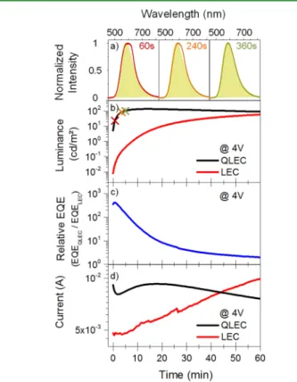
Figure 5 shows light intensity, calculated external quantum efficiency (EQE) ratio between QLEC and reference LEC, as
well as current flow as a function of time under a constant applied voltage of 4 V. As can be seen in Figure 5a, the emission of the QLEC is dominated by the iTMC already at 60 s after turn on, whereas the QD contribution can be neglected. The reference LEC device shows typical behavior with increasing light intensity in time (Figure 5b, red) due to the
Figure 3.(a) Normalized QD absorbance and LEC PL spectra. (b) Time-resolved PL measurements for LEC, QLED, and QLEC devices at a wavelength of 554 and 620 nm, respectively.
Figure 4.Luminance as a function of the applied voltage of QLEC (black line), reference QLED (blue) and reference LEC (red).
Figure 5.Long-term measurement of QLEC and LEC at a constant applied voltage of 4 V. (a) EL spectra of the hybrid device (solid line) compared to the EL of the reference LEC (green-colored area) at different time points given in the picture and marked by crosses in (b). (b) Luminance of QLEC (black line) and LEC (red line), (c) EQE ratio (EQEQLEC/EQELEC) between both devices versus time, and (d)
current through the QLEC (black line) and the LEC (red line) as a function of time.
reduction of injection barrier for electrons and holes by accumulation of ions at the electrodes and formation of the doped regions.20,55Also the transient current behavior of the reference LEC (Figure 5d, red) is in agreement with the typical transient behavior of iTMC-LECs17,20,21,29,56 as well as p-LECs,20,57,58which can be rationalized by the electrochemical doping of the active layer, assisted by the mobile ions.20 The injected electrons and holes recombine radiatively before they reach the opposite electrode, which explains the initial increase of the current and intensity. Both the intensity and the efficiency of the reference device reach their maximum after more than an hour. This is often attributed to the saturation point of the electrochemical doping of the p- and n-regions.59 Afterward, they both start to decay (not shown here), which is also typical for LECs and is often attributed to the exciton quenching by the doped n- and p-regions.20
In comparison with the reference LEC, the hybrid device shows initially 1.9 times higher current. Additionally, both light intensity and EQE are significantly enhanced for the hybrid device as compared to the LEC reference, especially directly after device turn-on (see Figure 5, panels b and c). Since electrons are believed to be the minority charge carriers in iTMC-LECs,29,60 and particularly in the case of the selected iTMC-emitter,61an increase of light intensity by several orders of magnitude in the range of 0−5 min should be attributed to an improved electron injection. The positions of HOMO and LUMO levels of the iTMC, as shown inFigure 1c, support the assumption of improved electron injection by the QD layer into the iTMC layer. The QLEC reaches the point of maximum intensity already after 15 min, whereas the reference LEC needs more than 1 h of device operation to reach its intensity maximum. This difference in turn-on time additionally indicates an improved electron injection. It should be noted that the increase in luminance cannot be attributed to additional contributions from the QDs. The QLEC emission spectra at different time points of constant voltage operation (60, 240, and 360 s of device operation, respectively, seeFigure 5a) show dominating LEC emission already at 60 s of operation.
Interestingly, the QLEC shows a significantly higher EQE compared to the reference LEC within thefirst tens of minutes of operation, which we attribute to an improved charge carrier balance. Charge carrier balance and thus EQE can either be improved by an enhancement of the minority charge carriers (e.g., improved electron injection as suggested above) or by reducing the currentflow of the majority charge carriers, in this case holes. Since the total current is considerably increased in the QLEC, we exclude possible hole blocking by the additional QD layer as the dominating mechanism for EQE enhancement. Furthermore, the increase of luminance is twice as strong as the increase of EQE (by factors of∼650 and ∼350, respectively) which hints again at an improved electron injection. A possible buffering effect and thus reduced quenching due to the QD layer placed between the iTMC layer and the electrode plays just a subordinating role (see Supporting Information). With progress in time of operation, the LEC device gains in performance by improved injection efficiency caused by the lowering of the injection barriers by the mobile ions and the LEC current becomes comparable to the values of the QLEC. Additionally, the QLEC device seems to degrade faster as the current is already decreasing after 15 min, which may be related to a faster propagation of the n-doping front due to the improved electron injection.
■
CONCLUSIONIn conclusion, we have demonstrated a hybrid device made of CdSe/CdS core−shell QDs and an Ir-based iTMC that shows light emission from both, red QDs and yellow LEC emitters. Electro- and photoluminescence measurements indicate that in the chosen device geometry, charge carriers can be injected directly into both light-emitting species which is beneficial for the implementation of QDs with various band gaps and thus creation of white light-emitting hybrid devices. The additional QD layer furthermore improves the electron injection into the active LEC layer, which leads to a faster device turn-on. The considerable improvement of the charge carrier balance by minority charge carriers, especially after device turn-on, results in an increased luminance and device efficiency. Overall, the results of this study indicate the possibility of creating color tunable iTMC LECs by implementing additional QDs and simultaneously improve device operation.
■
EXPERIMENTAL SECTION2.1. Device Fabrication. The discussed devices were fabricated via a spin-coating procedure under ambient air conditions. For the reference LEC, a layer of poly(3,4-ethylenedioxythiophene):poly-(styrenesulfonate) (PEDOT:PSS) was spin-coated onto a cleaned glass substrate with a 150 nm thick sputtered indium tin oxide (ITO) anode. After baking the PEDOT:PSS layer for 20 min at 150°C, the active LEC layer containing a blend of a long-term stable yellow ionic iridium complex ([Ir(ppy)2(pbpy)]+[PF6]−) and an ionic liquid
([BMIM]+[PF6]−) was spin-coated on top.
In the case of the reference QLED, the PEDOT:PSS layer was deposited as described above. To enable hole injection and transport, poly[N,N′-bis(4-butylphenyl)-N,N-bis(phenyl)-benzidine] (poly-TPD) was used as an established hole injection and transport layer35 for QLEDs. Red CdSe/CdS core/shell QDs of 7 nm size in average (see also TEM image inFigure 1b) were synthesized with a slightly modified recipe from the literature,62 having a CdSe core
radius of 2.1 nm, 6 monolayers CdS shell, and zinc blende crystal structure. An approximately 30 nm thick layer of QDs was spin-coated from toluene dispersion with a concentration of 25 mg/mL as the active light-emitting layer on top of the poly-TPD layer, resulting in the layer stack for the reference QLED.
For the hybrid QLEC device, PEDOT:PSS and a blend of iTMC and the ionic liquid (IL) were spin-coated in the same way as in the case of the LEC. The QD layer was spin-coated on top of the active LEC layer at the same conditions as in the case of the reference QLED (see also diagram inFigure 1a).
For all three devices, aluminum electrodes of 200 nm thickness and 7 mm2 active area were evaporated as a cathode on top of the
fabricated layer stacks. Since the iTMC-component typically shows a fast degradation during operation,19 both the reference LEC and the QLEC were encapsulated by epoxy and a glass plate on top under nitrogen atmosphere.
2.2. Device Characterization. For characterization of the voltage-dependent luminance behavior, the luminance was monitored by a calibrated photodiode (Newport Sensor 818-UV), whereby a Lab-View-controlled sourcemeter (Keathley 2601) was used for applying an increasing DC voltage in 0.1 V steps with 500 ms between two measurement points (Figure 4). The limit of the voltage range was set to 8 V to prevent degradation and damage of the devices. The Si-photodiode was calibrated by a Konica Minolta CS 2000A spectroradiometer with pure reference QLED and yellow iTMC LEC, respectively, to convert the measured photocurrent to luminance. For conversion of the QLEC luminance, the calibration factor of the LEC was used, since starting from 4 V the emission is completely dominated by the LEC emitter. The results inFigure 4are a representative selection of data for devices containing different QD and iTMC batches. We paid attention to using the same material batches for QLEC and reference devices production as well as identical ACS Applied Materials & Interfaces
measurement conditions. For time-dependent characterization of luminance, a voltage of 4 V was applied by the Keathley sourcemeter and luminance was simultaneously detected by the calibrated photodiode (Newport Sensor 818-UV). A bias of 4 V was chosen for this experiment since it corresponds to the turn-on voltage of the LEC, and both LEC and hybrid devices show good light emission and are not subject to fast degradation at this operation voltage.21,63
■
ASSOCIATED CONTENT*
S Supporting InformationThe Supporting Information is available free of charge on the ACS Publications websiteat DOI:10.1021/acsami.6b06833.
EQE for QLED, LEC, and QLEC as a function of applied voltage, time-resolved PL of the iTMC, and absolute EL spectra of the hybrid device (PDF)
■
AUTHOR INFORMATIONCorresponding Author
*E-mail:[email protected].
Author Contributions
The manuscript was written through contributions of all authors. All authors have given approval to thefinal version of the manuscript.
Funding
J.F, S.W., G.B., and E.N. are grateful to University Duisburg-Essen and OSRAM GmbH for funding the research. H.V.D. acknowledges the financial support from Singapore National Research Foundation under the programs of NRF-RF-2009-09 and NRF-CRP-6-2010-02 and the Science and Engineering Research Council, Agency for Science, Technology and Research (A*STAR) of Singapore; EU-FP7 Nanophotonics4E-nergy NoE; ESF-EURYI and TUBA-GEBIP. Y.K. acknowledges support from TUBITAK BIDEB.
Notes
The authors declare no competingfinancial interest.
■
ACKNOWLEDGMENTSWe are grateful to Dr. N. Gerlitzki of OSRAM for providing the iridium-based iTMC emitter and J.E. Namanga from OSRAM for the cyclic voltammetry measurement thereof. We kindly thank Dr. C. Liebscher from the ICAN team at University Duisburg-Essen for high-resolution TEM images of the CdSe/ CdS QDs.
■
REFERENCES(1) Meier, S. B.; Tordera, D.; Pertegás, A.; Roldán-Carmona, C.; Ortí, E.; Bolink, H. J. Light-Emitting Electrochemical Cells: Recent Progress and Future Prospects. Mater. Today 2014, 17, 217−223.
(2) Sandström, A.; Edman, L. Towards High-Throughput Coating and Printing of Light-Emitting Electrochemical Cells: A Review and Cost Analysis of Current and Future Methods. Energy Technol. 2015, 3, 329−339.
(3) Asadpoordarvish, A.; Sandström, A.; Larsen, C.; Bollström, R.; Toivakka, M.; Österbacka, R.; Edman, L. Light-Emitting Paper. Adv. Funct. Mater. 2015, 25, 3238−3245.
(4) Zhang, Z.; Guo, K.; Li, Y.; Li, X.; Guan, G.; Li, H.; Luo, Y.; Zhao, F.; Zhang, Q.; Wei, B.; Pei, Q.; Peng, H. A Colour-Tunable, Weavable Fibre-Shaped Polymer Light-Emitting Electrochemical Cell. Nat. Photonics 2015, 9, 233−238.
(5) Reineke, S.; Thomschke, M.; Lüssem, B.; Leo, K. White Organic Light-Emitting Diodes: Status and Perspective. Rev. Mod. Phys. 2013, 85, 1245−1293.
(6) Kathirgamanathan, P.; Bushby, L. M.; Kumaraverl, M.; Ravichandran, S.; Surendrakumar, S. Electroluminescent Organic and
Quantum Dot LEDs: The State of the Art. J. Disp. Technol. 2015, 11, 480−493.
(7) Shirasaki, Y.; Supran, G. J.; Bawendi, M. G.; Bulović, V. Emergence of Colloidal Quantum-Dot Light-Emitting Technologies. Nat. Photonics 2012, 7, 13−23.
(8) Mashford, B. S.; Stevenson, M.; Popovic, Z.; Hamilton, C.; Zhou, Z.; Breen, C.; Steckel, J.; Bulovic, V.; Bawendi, M.; Coe-Sullivan, S.; Kazlas, P. T. High-Efficiency Quantum-Dot Light-Emitting Devices with Enhanced Charge Injection. Nat. Photonics 2013, 7, 407−412.
(9) Dai, X.; Zhang, Z.; Jin, Y.; Niu, Y.; Cao, H.; Liang, X.; Chen, L.; Wang, J.; Peng, X. Solution-Processed, High-Performance Light-Emitting Diodes Based on Quantum Dots. Nature 2014, 515, 96−99. (10) Costa, R. D.; Ortí, E.; Bolink, H. J.; Monti, F.; Accorsi, G.; Armaroli, N. Luminescent Ionic Transition-Metal Complexes for Light-Emitting Electrochemical Cells. Angew. Chem., Int. Ed. 2012, 51, 8178−8211.
(11) Pei, Q.; Yu, G.; Zhang, C.; Yang, Y.; Heeger, A. J. Polymer Light-Emitting Electrochemical Cells. Science 1995, 269, 1086−1088. (12) deMello, J.; Tessler, N.; Graham, S.; Friend, R. Ionic Space-Charge Effects in Polymer Light-Emitting Diodes. Phys. Rev. B: Condens. Matter Mater. Phys. 1998, 57, 12951−12963.
(13) van Reenen, S.; Matyba, P.; Dzwilewski, A.; Janssen, R. A. J.; Edman, L.; Kemerink, M. A Unifying Model for the Operation of Light-Emitting Electrochemical Cells. J. Am. Chem. Soc. 2010, 132, 13776−13781.
(14) van Reenen, S.; Janssen, R. A. J.; Kemerink, M. Doping Dynamics in Light-Emitting Electrochemical Cells. Org. Electron. 2011, 12, 1746−1753.
(15) Baldo, M.; O’Brien, D. F.; You, Y.; Shoustikov, A.; Sibley, S.; Thompson, M. E.; Forrest, S. R. Highly Efficient Phosphorescent Emission from Organic Electroluminescent Devices. Nature 1998, 395, 151−154.
(16) Hu, T.; He, L.; Duan, L.; Qiu, Y. Solid-State Light-Emitting Electrochemical Cells Based on Ionic Iridium(iii) Complexes. J. Mater. Chem. 2012, 22, 4206−4215.
(17) Tordera, D.; Meier, S.; Lenes, M.; Costa, R. D.; Ortí, E.; Sarfert, W.; Bolink, H. J. Simple, Fast, Bright, and Stable Light Sources. Adv. Mater. 2012, 24, 897−900.
(18) Bünzli, A. M.; Constable, E. C.; Housecroft, C. E.; Prescimone, A.; Zampese, J. A.; Longo, G.; Gil-Escrig, L.; Pertegás, A.; Ortí, E.; Bolink, H. J. Exceptionally Long-Lived Light-Emitting Electrochemical Cells: Multiple Intra-Cation π-Stacking Interactions in [Ir(ĈN) 2
(N̂N)][PF6] Emitters. Chem. Sci. 2015, 6, 2843−2852.
(19) Asadpoordarvish, A.; Sandström, A.; Tang, S.; Granström, J.; Edman, L. Encapsulating Light-Emitting Electrochemical Cells for Improved Performance. Appl. Phys. Lett. 2012, 100, 193508.
(20) van Reenen, S.; Akatsuka, T.; Tordera, D.; Kemerink, M.; Bolink, H. J. Universal Transients in Polymer and Ionic Transition Metal Complex Light-Emitting Electrochemical Cells. J. Am. Chem. Soc. 2013, 135, 886−891.
(21) Lenes, M.; Garcia-Belmonte, G.; Tordera, D.; Pertegás, A.; Bisquert, J.; Bolink, H. J. Operating Modes of Sandwiched Light-Emitting Electrochemical Cells. Adv. Funct. Mater. 2011, 21, 1581− 1586.
(22) Hoven, C. V.; Wang, H.; Elbing, M.; Garner, L.; Winkelhaus, D.; Bazan, G. C. Chemically Fixed P−n Heterojunctions for Polymer Electronics by Means of Covalent B−F Bond Formation. Nat. Mater. 2010, 9, 249−252.
(23) Gautier, B.; Gao, J. Polymer Light-Emitting Devices Based on a Polymer/salt Mixture. Appl. Phys. Lett. 2012, 101, No. 093302.
(24) Parker, S. T.; Slinker, J. D.; Lowry, M. S.; Cox, M. P.; Bernhard, S.; Malliaras, G. G. Improved Turn-on Times of Iridium Electro-luminescent Devices by Use of Ionic Liquids. Chem. Mater. 2005, 17, 3187−3190.
(25) Shen, Y.; Kuddes, D. D.; Naquin, C. A.; Hesterberg, T. W.; Kusmierz, C.; Holliday, B. J.; Slinker, J. D. Improving Light-Emitting Electrochemical Cells with Ionic Additives. Appl. Phys. Lett. 2013, 102, 203305.
(26) Yu, Z.; Wang, M.; Lei, G.; Liu, J.; Li, L.; Pei, Q. Stabilizing the Dynamic P−i−n Junction in Polymer Light-Emitting Electrochemical Cells. J. Phys. Chem. Lett. 2011, 2, 367−372.
(27) Zhang, J.; Zhou, L.; Al-Attar, H. A.; Shao, K.; Wang, L.; Zhu, D.; Su, Z.; Bryce, M. R.; Monkman, A. P. Efficient Light-Emitting Electrochemical Cells (LECs) Based on Ionic Iridium(III) Complexes with 1,3,4-Oxadiazole Ligands. Adv. Funct. Mater. 2013, 23, 4667− 4677.
(28) Constable, E. C.; Housecroft, C. E.; Schneider, G. E.; Zampese, J. A.; Bolink, H. J.; Pertegás, A.; Roldan-Carmona, C. Red Emitting [Ir(ĈN)2(N̂N)]+ Complexes Employing Bidentate 2,2 ′:6′,2″-Terpyr-idine Ligands for Light-Emitting Electrochemical Cells. Dalton Trans. 2014, 43, 4653−4667.
(29) Liao, C.-T.; Chen, H.-F.; Su, H.-C.; Wong, K.-T. Tailoring Balance of Carrier Mobilities in Solid-State Light-Emitting Electro-chemical Cells by Doping a Carrier Trapper to Enhance Device Efficiencies. J. Mater. Chem. 2011, 21, 17855−17862.
(30) Sunesh, C. D.; Mathai, G.; Choe, Y. Green and Blue−green Light-Emitting Electrochemical Cells Based on Cationic Iridium Complexes with 2-(4-Ethyl-2-Pyridyl)-1H-Imidazole Ancillary Ligand. Org. Electron. 2014, 15, 667−674.
(31) He, L.; Duan, L.; Qiao, J.; Dong, G.; Wang, L.; Qiu, Y. Highly Efficient Blue-Green and White Light-Emitting Electrochemical Cells Based on a Cationic Iridium Complex with a Bulky Side Group. Chem. Mater. 2010, 22, 3535−3542.
(32) Wu, J.; Li, F.; Zeng, Q.; Nie, C.; Ooi, P. C.; Guo, T.; Shan, G.; Su, Z. Flexible Blue-Green and White Light-Emitting Electrochemical Cells Based on Cationic Iridium Complex. Org. Electron. 2016, 28, 314−318.
(33) Bolink, H. J.; Coronado, E.; Costa, R. D.; Ortí, E.; Sessolo, M.; Graber, S.; Doyle, K.; Neuburger, M.; Housecroft, C. E.; Constable, E. C. Long-Living Light-Emitting Electrochemical Cells - Control through Supramolecular Interactions. Adv. Mater. 2008, 20, 3910− 3913.
(34) Bolink, H. J. Progress towards Low Cost Flexible Lighting Solutions. European Energy Innovation 2013, 39.
(35) Kwak, J.; Bae, W. K.; Lee, D.; Park, I.; Lim, J.; Park, M.; Cho, H.; Woo, H.; Yoon, D. Y.; Char, K.; Lee, S.; Lee, C. Bright and Efficient Full-Color Colloidal Quantum Dot Light-Emitting Diodes Using an Inverted Device Structure. Nano Lett. 2012, 12, 2362−2366.
(36) Norell Bader, A. J.; Ilkevich, A. A.; Kosilkin, I. V.; Leger, J. M. Precise Color Tuning via Hybrid Light-Emitting Electrochemical Cells. Nano Lett. 2011, 11, 461−465.
(37) Qian, G.; Lin, Y.; Wantz, G.; Davis, A. R.; Carter, K. R.; Watkins, J. J. Saturated and Multi-Colored Electroluminescence from Quantum Dots Based Light Emitting Electrochemical Cells. Adv. Funct. Mater. 2014, 24, 4484−4490.
(38) Sun, Q.; Wang, Y. A.; Li, L. S.; Wang, D.; Zhu, T.; Xu, J.; Yang, C.; Li, Y. Bright, Multicoloured Light-Emitting Diodes Based on Quantum Dots. Nat. Photonics 2007, 1, 717−722.
(39) Costa, R. D.; Ortí, E.; Bolink, H. J.; Graber, S.; Schaffner, S.; Neuburger, M.; Housecroft, C. E.; Constable, E. C. Archetype Cationic Iridium Complexes and Their Use in Solid-State Light-Emitting Electrochemical Cells. Adv. Funct. Mater. 2009, 19, 3456−3463.
(40) Wang, J.; Tang, S.; Sandström, A.; Edman, L. Combining an Ionic Transition Metal Complex with a Conjugated Polymer for Wide-Range Voltage-Controlled Light-Emission Color. ACS Appl. Mater. Interfaces 2015, 7, 2784−2789.
(41) Shirasaki, Y.; Supran, G. J.; Tisdale, W. A.; Bulović, V. Origin of Efficiency Roll-Off in Colloidal Quantum-Dot Light-Emitting Diodes. Phys. Rev. Lett. 2013, 110, 217403.
(42) Tessler, N. Efficient Near-Infrared Polymer Nanocrystal Light-Emitting Diodes. Science 2002, 295, 1506−1508.
(43) O’Connor, E.; O’Riordan, A.; Doyle, H.; Moynihan, S.; Cuddihy, A.; Redmond, G. Near-Infrared Electroluminescent Devices Based on Colloidal HgTe Quantum Dot Arrays. Appl. Phys. Lett. 2005, 86, 201114.
(44) Bolink, H. J.; Cappelli, L.; Cheylan, S.; Coronado, E.; Costa, R. D.; Lardiés, N.; Nazeeruddin, M. K.; Ortí, E. Origin of the Large
Spectral Shift in Electroluminescence in a Blue Light Emitting Cationic Iridium(iii) Complex. J. Mater. Chem. 2007, 17, 5032−5041.
(45) Dabbousi, B. O.; Bawendi, M. G.; Onitsuka, O.; Rubner, M. F. Electroluminescence from CdSe Quantum-Dot/polymer Composites. Appl. Phys. Lett. 1995, 66, 1316.
(46) Shen, H.; Lin, Q.; Wang, H.; Qian, L.; Yang, Y.; Titov, A.; Hyvonen, J.; Zheng, Y.; Li, L. S. Efficient and Bright Colloidal Quantum Dot Light-Emitting Diodes via Controlling the Shell Thickness of Quantum Dots. ACS Appl. Mater. Interfaces 2013, 5, 12011−12016.
(47) Ji, W.; Jing, P.; Zhang, L.; Li, D.; Zeng, Q.; Qu, S.; Zhao, J. The Work Mechanism and Sub-Bandgap-Voltage Electroluminescence in Inverted Quantum Dot Light-Emitting Diodes. Sci. Rep. 2014, 4, 6974. (48) Wood, V.; Bulović, V. Colloidal Quantum Dot Light-Emitting Devices. Nano Rev. 2010, 1, 1−7.
(49) Demir, H. V.; Nizamoglu, S.; Erdem, T.; Mutlugun, E.; Gaponik, N.; Eychmüller, A. Quantum Dot Integrated LEDs Using Photonic and Excitonic Color Conversion. Nano Today 2011, 6, 632−647.
(50) Anikeeva, P. O.; Madigan, C. F.; Coe-Sullivan, S. A.; Steckel, J. S.; Bawendi, M. G.; Bulović, V. Photoluminescence of CdSe/ZnS Core/shell Quantum Dots Enhanced by Energy Transfer from a Phosphorescent Donor. Chem. Phys. Lett. 2006, 424, 120−125.
(51) Ji, W.; Jing, P.; Xu, W.; Yuan, X.; Wang, Y.; Zhao, J.; Jen, A. K.-Y. High Color Purity ZnSe/ZnS Core/shell Quantum Dot Based Blue Light Emitting Diodes with an Inverted Device Structure. Appl. Phys. Lett. 2013, 103, No. 053106.
(52) Förster, T. Energy Migration and Fluorescence. J. Biomed. Opt. 2012, 17, No. 011002.
(53) Lakowicz, J. R. Principles of Fluorescence Spectroscopy, 3rd ed.; Springer: New York, 2006.
(54) Lutich, A. A.; Jiang, G.; Susha, A. S.; Rogach, A. L.; Stefani, F. D.; Feldmann, J. Energy Transfer versus Charge Separation in Type-II Hybrid Organic−Inorganic Nanocomposites. Nano Lett. 2009, 9, 2636−2640.
(55) Shavaleev, N. M.; Scopelliti, R.; Grätzel, M.; Nazeeruddin, M. K.; Pertegás, A.; Roldán-Carmona, C.; Tordera, D.; Bolink, H. J. Pulsed-Current versus Constant-Voltage Light-Emitting Electrochem-ical Cells with Trifluoromethyl-Substituted Cationic Iridium(iii) Complexes. J. Mater. Chem. C 2013, 1, 2241−2248.
(56) Su, H.-C.; Chen, H.-F.; Fang, F.-C.; Liu, C.-C.; Wu, C.-C.; Wong, K.-T.; Liu, Y.-H.; Peng, S.-M. Solid-State White Light-Emitting Electrochemical Cells Using Iridium-Based Cationic Transition Metal Complexes. J. Am. Chem. Soc. 2008, 130, 3413−3419.
(57) van Reenen, S.; Janssen, R. A. J.; Kemerink, M. Dynamic Processes in Sandwich Polymer Light-Emitting Electrochemical Cells. Adv. Funct. Mater. 2012, 22, 4547−4556.
(58) Davis, Y. A.; Crooker, P. P.; Haegel, N. M.; Yoshioka, Y.; MacKenzie, J. D. Transient Capacitance of Light-Emitting Electro-chemical Cells. Appl. Phys. Lett. 2011, 99, 233306.
(59) Matyba, P.; Andersson, M. R.; Edman, L. On the Desired Properties of a Conjugated Polymer-Electrolyte Blend in a Light-Emitting Electrochemical Cell. Org. Electron. 2008, 9, 699−710.
(60) Park, B.; Huh, Y. H.; Jeon, H. G.; Park, C. H.; Kang, T. K.; Kim, B. H.; Park, J. Solution Processable Single Layer Organic Light-Emitting Devices with a Single Small Molecular Ionic Iridium Compound. J. Appl. Phys. 2010, 108, 094506.
(61) Meier, S. B.; van Reenen, S.; Lefevre, B.; Hartmann, D.; Bolink, H. J.; Winnacker, A.; Sarfert, W.; Kemerink, M. Dynamic Doping in Planar Ionic Transition Metal Complex-Based Light-Emitting Electro-chemical Cells. Adv. Funct. Mater. 2013, 23, 3531−3538.
(62) Chen, O.; Zhao, J.; Chauhan, V. P.; Cui, J.; Wong, C.; Harris, D. K.; Wei, H.; Han, H.-S.; Fukumura, D.; Jain, R. K.; Bawendi, M. G. Compact High-Quality CdSe−CdS Core−shell Nanocrystals with Narrow Emission Linewidths and Suppressed Blinking. Nat. Mater. 2013, 12, 445−451.
(63) Slinker, J. D.; Rivnay, J.; Moskowitz, J. S.; Parker, J. B.; Bernhard, S.; Abruña, H. D.; Malliaras, G. G. Electroluminescent Devices from Ionic Transition Metal Complexes. J. Mater. Chem. 2007, 17, 2976−2988.