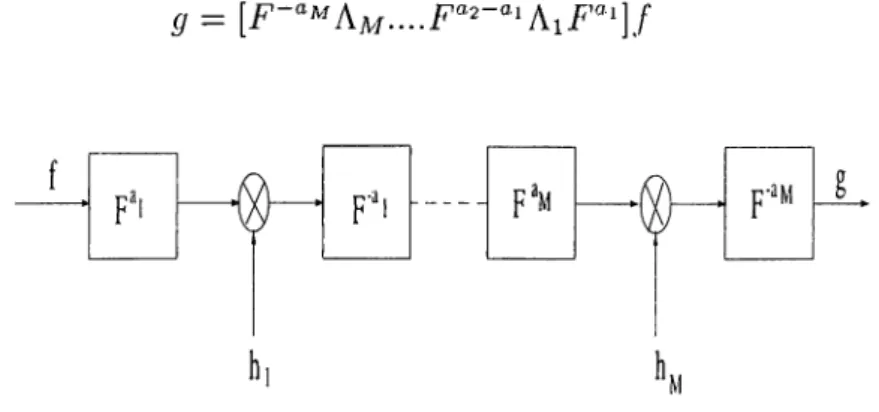
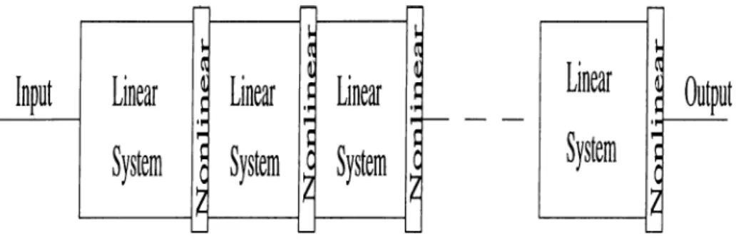
Feature extraction with the fractional Fourier transform
Tam metin
Şekil

Benzer Belgeler
Bu noktadan yola çıkarak, bu çalışmada belge aramada resim bazlı kelime sorgusu yöntemi seçildi ve kelime sorgusu yapmak için iki değişik yöntem önerildi: eğim
(d) Efficiency ratios: By using these ratios the efficiency of specific assets are measured instead of overall efficiency of assets.. Then, in each sector the means and
Table 2 Responses of the instructors to questions related to priority of hand skills in education, relation of jury member’s familiarity in a presentation technique and her
Learning a relational concept description in terms of given examples and back- ground clauses in the language of logic programs is named as logic program syn- thesis or inductive
Bu çalışmada, nakil uygulanmamış balıkların nakilden hemen sonra (t-0), nakilden 6 saat sonra (t-6) kan, ve kas, karaciğer, böbrek dokularına ait MDA değerlerinin kontrol
De nouveaux ateliers ont été créés pour la construction des b lindages et des m
B unları ben yazdım , şiir sayılır sa ben de şair oldum dem ektir. K adlrcan K A
■‘Resimlerini bir bir inceledi ğimizde varacağımız sonuçlar şunlar olabilir; sanal diliminde “ konlur” dediğimiz, biçimleri sınırlandıran, çizgi
