Power-Source-Aware Backbone Routing
in Wireless Sensor Networks
Metin Tekkalmaz
∗and Ibrahim Korpeoglu
∗∗Department of Computer Engineering, Bilkent University, Ankara, Turkey
Email: {metint, korpe}@cs.bilkent.edu.tr
Abstract—Due to the limited energy-source and mostly unat-tended nature of the wireless sensor networks, efficient use of energy has a critical importance on the lifetime of the applications accomplished by such networks. Although in most of the cases sensor nodes are battery-powered, there are application scenarios in which battery- and mains-powered nodes coexist. In this paper, we present an approach and algorithms based on this approach that increase the lifetime of wireless sensor networks in such heterogeneous deployment cases. In the proposed approach, a backbone, which is composed of mains-powered nodes, sink, and battery-powered nodes if required, is constructed to relay the data packets. Simulation results show that, the proposed approach is able to increase the network lifetime up to more than a factor of two, compared to the case in which battery- and mains-powered nodes are not distinguished.
I. INTRODUCTION
Wireless Sensor Networks (WSNs) are used to monitor physical and environmental conditions in a wide range of civilian and military applications. Such applications include intrusion detection, disaster management, environment and habitat monitoring, home automation, industrial process con-trol and monitoring.
In many application scenarios, sensor nodes are randomly deployed in large quantities using methods like dropping from an air vehicle due to reasons such as safety, harsh environ-mental conditions or ease of application. In those cases all the nodes are battery-powered, hence have a limited source of energy. Due to this restriction, careful use of energy has vital importance as far as the lifetime of the WSNs is considered. On the other hand in some of the application scenarios, it is possible, preferred or required to deploy at least some of the nodes in a manual fashion. This is also the case for wireless sensor deployments within a factory, office building or house. In such a deployment environment, some of the nodes can benefit from the continuous energy source of the facility. Mains-powered nodes would be preferred wherever possible in order to reduce maintenance costs, and battery-powered nodes would be used where installing power lines is costly or practically impossible.
In this paper, we present an approach that increases the lifetime of heterogeneous WSNs in which both battery- and mains-powered nodes coexist. The basic idea behind the proposed approach is to form a backbone consisting of mains-powered nodes and the sink in order to relay the packets between the sink and the sensor nodes. However, sink and
the mains-powered sensor nodes might not always form a connected topology. Therefore battery-powered nodes are also used to provide a connected backbone for the rest of the network.
The remainder of this paper is organized as follows: In the next section, related previous studies are summarized. The proposed approach and the related algorithms are described in Section III. The simulation results presenting the performance of the algorithms are given in Section IV. Finally, in Section V, the paper is concluded with some future work.
II. RELATEDWORK
Due to the limited energy-source and mostly unattended nature of WSNs, efficient use of energy in order to increase the network lifetime has been one of the most studied subjects related to WSNs. Vast majority of these studies are related to energy efficient data dissemination and gathering, in other words, routing in WSNs. As Simplot-Ryl et al. enumerate in [1], backbone-based approaches for data dissemination and gathering are rather well-studied. As in other related studies, in [1], backbone is considered to be either neighbor- or area-dominating set of a network. In the former, all the nodes are either part of the backbone or in one-hop distance of it, and in the latter, the whole area is in the sensing range of the nodes constituting the backbone.
Since finding the minimum connected dominating set (CDS) is NP-complete, approaches in the literature are based on cen-tral and distributed heuristics. Although cencen-tralized algorithms can provide bounds on the size of CDS, such as in [2], they require global information, increasing the messaging overhead. Localized approaches, in which only a limited neighborhood information is shared, are based on either deterministic or probabilistic algorithms. Span, presented in [3], is an example of probabilistic algorithms. In Span, a node either sleeps or takes part in the backbone randomly, based on its residual energy and the benefit to its neighbors if it stays awake. In a similar algorithm called EAD [4], Boukerche et al. try to find a spanning tree with many leaf nodes. In EAD, nodes with higher residual energy have a higher chance of not being a leaf-node. As another distributed algorithm, in ASCENT [5], nodes participate in sensing and routing tasks according to the packet-losses due to lack of relay nodes and packet-losses due to collisions. Hence, the aim is to keep only a subset of the nodes alive to preserve energy. Cell-based approaches are
a type of CDS-based ones and employed in different studies including [6] and [7]. In both studies the area is divided into cells and only a single node in each cell is kept alive for routing. The major drawback of these studies is that they need to know the locations of the nodes.
In the studies mentioned so far, the aim is to find a CDT. Differently in [8], the authors present different protocols that ensure k-connectedness of dominating sets, in favor of fault tolerance. In a different study that take fault tolerance into account, Kashyap et al. [9] add relay nodes to the WSN in order to provide a k-connected backbone.
In our study, different from the previous studies, we assume that the sensor nodes are heterogeneous as far as their power-sources are considered. Although studies, such as [2] and [3], that take residual energy into account, can be applied for this case, prior knowledge of different power-sources enables specialized solutions, since the energy of the devices change in time but their power-sources do not. In this study, we also adapt the definition of backbone: in our case, a backbone consists of a connected set of mains-powered nodes, compared to the CDS of all nodes. As mentioned earlier, there are both central and localized algorithms for backbone construction. For the approach presented in this paper, both central and distributed implementations are possible as explained in Sec-tion III. In any case, it falls into the deterministic category, hence if there is a connected backbone, the algorithms based on the proposed approach are able to construct it, whereas in randomized algorithms backbone connectivity is highly affected by the node density. A subset of the proposed al-gorithms take fault tolerance into account similar to [8] and [9], but different from them the proposed algorithms try to increase the number of vertex disjoint paths between pair of mains-powered nodes on the backbone, rather than trying to achieve k-connectedness of the whole backbone. As another difference with [9] we assume that the set of sensor nodes and their locations are fixed.
III. THEALGORITHMS
As mentioned earlier, we assume battery- and mains-powered sensor nodes coexist in the environment and the proposed approach makes use of mains-powered nodes to increase the overall lifetime of the sensor network. Basically, the proposed approach forms a backbone which consists of the sink, all of the mains-powered sensor nodes, which are accessible from the sink, and some of the battery-powered nodes to interconnect mains-powered nodes, if required. Then it uses this backbone to route packets between the sink and the sensor nodes.
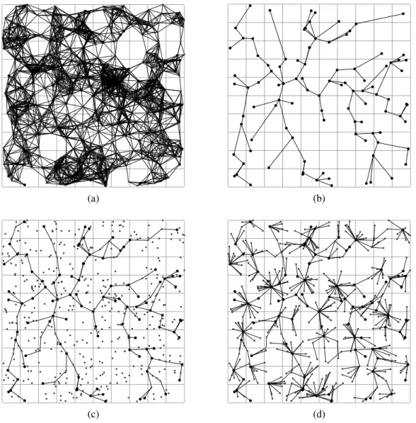
In Figure 1, a sample network is given in order to explain the proposed approach. The sample network consists of 500 sensor nodes, 100 of which, including the sink, are mains-powered. The sink is located at the center of the area. In the figures, the battery-powered nodes are denoted by small circles and the mains-powered nodes are shown as larger circles. In Figure 1 (a), visibility graph of the network is given, that is, if a node is in direct communication range of another node,
there is an edge between the vertices representing these two nodes. Given such a visibility graph, the approach can extract a backbone similar to the one shown in Figure 1 (c). Connec-tivity information of the mains-powered nodes, as depicted in Figure 1 (b), is used for the formation of the backbone, which is explained later in this section. Please note that all the mains-powered nodes take part in the backbone and in some cases battery-powered nodes are used to interconnect them. Finally in Figure 1 (d), connectivity graph of the network, as the rest of the nodes are connected to the backbone, is shown.
The proposed approach can be described by the following three-step procedure, in a more formal manner:
1) Reduce the visibility graph G = (V, E) to a secondary graph G0= (V0, E0) such that
a) V0 ← {v ∈ V | v is mains-powered}
b) ∀ vi, vj ∈ V0, the edge (vi, vj) ∈ E0 ⇐⇒
(vi, vj) ∈ E or ∃ a simple path p = (v1, v2, ..., vn)
between vi and vj in G s.t. v1, v2, ..., vn are all
battery-powered and |p| < T
c) Assign a cost value to each edge e0 ∈ E0
2) Extract a backbone
a) Find a spanning tree on G0
b) Map the spanning tree on G0 to a tree on G
3) Connect the remaining nodes to the backbone
This procedure is actually a framework for a class of algorithms, rather than a complete description of a single algorithm, since there are several alternatives for some of its steps. Let us explain the procedure step by step with the alternatives where necessary. In the first step, the original visibility graph of the network is reduced to a secondary graph in which the vertices are the mains-powered nodes (step 1-a) and the edges represent the connectivity of these nodes. Two mains-powered node is assumed to be connected if either they are in direct communication range of each other or there is a path between them shorter than a threshold and consisting of only battery-powered nodes (step 1-b). In step 1-c, the cost values are assigned to the edges of the secondary graph to be used in the second step of the procedure. Two alternatives are considered for this step, given two vertices, representing the mains-powered nodes, and an edge between them: 1. Minimum number of battery-powered nodes in between the two mains-powered nodes, 2. A value inversely proportional to the number of vertex disjoint paths (shorter than a threshold, T , and consisting of only battery-powered nodes) between the two mains-powered nodes. The first alternative is expected to reduce the amount of energy consumed by the battery-powered nodes, whereas the second alternative is considered for fault tolerance, that is if one of the paths between the mains-powered nodes become unusable due to a node failure, another path can be chosen from the alternatives. In the second step of the procedure the backbone is formed. First a spanning tree on the secondary graph is found (step 2-a) similar to the one in Figure 1 (b). This spanning tree is used as the basis of the backbone on the actual network. Minimum spanning tree (MST) and shortest path tree (SPT) routed at the sink are
(a) (b)
(c) (d)
Fig. 1. (a) Visibility, (b) mains-powered device connectivity, (c) backbone, (d) connectivity graphs of a sample sensor network
considered as alternatives. Although MST is expected to give better network-wide result than SPT, SPT has a less complex distributed implementation. Backbone is yielded by mapping the spanning tree on the secondary graph back to a tree on the original graph (step 2-b). This corresponds to mapping each edge of the secondary graph to a path (therefore battery-powered nodes constituting that path) between the endpoints of that edge (therefore the mains-powered nodes). In the algorithms, this path is chosen to be the shortest one. The mapping can be seen in Figure 1 (b) and (c). Finally, in the last step of the procedure, disconnected nodes are connected to the nodes that are part of the backbone (step 3). Although there might be other alternatives, in the algorithms, mains-powered nodes are chosen to have precedence over battery-powered nodes to be parents of the connecting nodes. The final connectivity of the nodes is similar to the one in Figure 1 (d). So far the algorithms based on the proposed approach are described but their implementations are not explained. One of the alternatives is the central implementation. In the central
implementation, each node sends its neighbors to the sink, the sink executes the algorithm and sends back the final connectivity to the nodes according to the algorithm results. Whenever neighborhood information of a node changes, the sink is informed about the situation and the topology is restructured according to the current visibility of the nodes, if required. Second alternative is the distributed implementation. Although both MST and SPT have distributed implementations available in the literature, finding the MST of a graph in a distributed manner is more complex than finding the SPT. In a distributed implementation of SPT case, local informa-tion, which includes neighboring mains-powered nodes (other mains-powered nodes connected directly or through a limited number of battery-powered nodes) and the path alternatives to them, can be collected at mains-powered nodes. Hence each mains-powered node can have a partial view of the visibility graph. In order to construct the SPT, distance to the sink can be shared between connected mains-powered nodes. Once a mains-powered node determines its parent, which has
the minimum distance to the sink among its mains-powered neighbors, it may also decide the path to its parent among the alternatives. This corresponds to a partial mapping of the secondary graph to the original graph handling part of the step 2-b of the procedure. Nodes that are not declared as part of the backbone by the mains-powered nodes can be connected to the backbone as in the last step of the procedure.
IV. SIMULATIONRESULTS
In order to evaluate the effectiveness and the performance of the algorithms described in Section III, a set of simulations were run. In the simulations, the power-source-aware backbone approach was compared with the shortest path approach, in which battery- and mains-powered nodes are not distinguished and each node is connected to the sink via the shortest possible path. For the backbone approach, either the minimum number of battery-powered nodes or 1/d, where d is the number of vertex disjoint paths bounded by a threshold, T , was chosen to be the cost assigned to the edges of the secondary graph (referred as # of BP-Nodes and # of Disjoint Paths respectively). T is chosen to be 4, and although polynomial time algorithms exist to find the maximum number of vertex-disjoint paths for T ≤ 4, a greedy approach is followed to find a lower bound on the number of vertex-disjoint paths. On the other hand, either the minimum spanning tree (MST) or the shortest path tree (SPT) algorithm was applied to find a spanning tree on the secondary graph.
In the simulations, the network size was chosen to be 500 sensor nodes, a certain ratio of which were mains-powered. All the sensor nodes were distributed over an area of 500m by 500m and the communication range of a node was set to be 50m, independent of its power-source. The sink was located at the center of the area and was mains-powered. The simulation results were averaged over 20 runs, in each of which the loca-tions of the sensor nodes were determined pseudo-randomly as described in [10]. A sensor node was assumed to be reachable if it is alive and there is a path between the node and the sink. Each simulation run was stopped when more than half of the sensor-nodes (i.e. 250 sensor nodes) were unreachable. In the simulations, we assumed that each sensor node sends data to the sink periodically. At each round of data gathering, data is collected once from each sensor node. We also assumed that the data is aggregated at each node.
A simple energy model is applied in the simulations. In [11], the energy consumption ratio of a wireless device is measured as 1:1.05:1.4 for idle, receive, and send periods, respectively. The energy consumption of the sensor nodes were determined in accordance with this measurement. Hence, receiving a data packet was assumed to consume 1.05 units of energy, whereas sending a data packet was assumed to consume 1.4 units of energy. Idle periods of sensor nodes were ruled out, since total idle period of a node is almost equal for any approach compared in the simulations. Furthermore, the energy consumed during data aggregation was assumed to be negligible. In each simulation run, all the battery-powered nodes had 1000 units of energy, initially.
250 300 350 400 450 500 0 100 200 300 400 500 600 700 800
Reachable Node Cou
nt Rounds # of BP-Nodes + MST # of Disjoint Paths + MST # of BP-Nodes + SPT # of Disjoint Paths + SPT Shortest Path
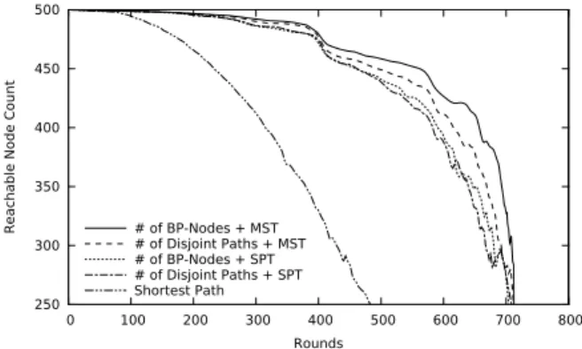
Fig. 2. Number of Rounds Passed vs. Number of Nodes Reachable from the Sink (Mains-Powered Node Ratio: 20%)
Figure 2 depicts the number of reachable nodes compared to the number of rounds. In the simulations, the backbone approach exhibited a significant improvement over shortest path algorithm. Note that the network lifetime until 20% of the nodes (i.e. 100 nodes) become unreachable for the # of BP-Nodes+ MST case was more than twice as long as the shortest path case. Also note that, MST performed better than SPT as the spanning tree algorithm and # of BP-Nodes performed better than # of Disjoint Paths as the cost function, as far as the network lifetime is considered.
0 0.5 1 1.5 2 2.5 3 0 100 200 300 400 500 600 700 800
Average Energy Con
sumption per Round
Rounds # of BP-Nodes + MST # of Disjoint Paths + MST # of BP-Nodes + SPT # of Disjoint Paths + SPT Shortest Path
Fig. 3. Number of Rounds Passed vs. Average Energy Consumption per Round (Mains-Powered Node Ratio: 20%)
Figure 3 presents average energy consumption of the battery-powered nodes during their lifetime. The backbone approach had an average energy consumption of around 1.5 units. Considering that each node must transmit exactly once at each round and one packet transmission consumed 1.4 units of energy in the simulations, the packets were mostly relayed by mains-powered nodes. As the rounds increased, the average energy consumption decreased for the shortest path case. The reason was probably the increase in the ratio of mains-powered nodes among the reachable nodes, which in turn decreased the burden on the remaining battery-powered nodes.
In the proposed approach, since the packets are relayed through a backbone with certain restrictions such as including all the mains-powered nodes, suboptimal results are expected as far as the average path length to the sink is considered. As
0 5 10 15 20 0 100 200 300 400 500 600 700 800
Average Path Length
(hops) Rounds # of BP-Nodes + MST # of Disjoint Paths + MST # of BP-Nodes + SPT # of Disjoint Paths + SPT Shortest Path
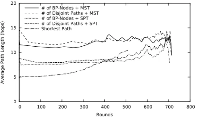
Fig. 4. Number of Rounds Passed vs. Average Path Length to the Sink (Mains-Powered Node Ratio: 20%)
depicted in Figure 4, the average path lengths were doubled on the average in MST cases compared to the shortest path case, which ensures that each node is connected to the sink via the shortest possible path. On the other hand in the SPT cases, the average path length was at most 40% longer compared to the shortest path case. Note that for the shortest path case after around 250 rounds, which corresponds to about 50 (i.e. 10%) unreachable nodes, the average path length exhibited a noticeable increase and eventually exceeded the SPT cases. This was probably due to the battery-powered node failures at critical locations, which led to longer paths.
300 350 400 450 500 550 600 650 700 750 5 10 15 20 25 30 35 40 Lifetime (Rounds)
Mains-Powered Node Ratio (%) # of BP-Nodes + MST # of Disjoint Paths + MST # of BP-Nodes + SPT # of Disjoint Paths + SPT Shortest Path Upper Bound
Fig. 5. Mains-Powered Node Ratio vs. Lifetime
Finally in Figure 5, effect of mains-powered node ratio on the performance of the algorithms is presented. The back-bone approach outperformed the shortest path algorithm and stabilized around 715 rounds, which is the theoretical upper bound considering battery-powered nodes initially had 1000 units of energy and each transmission consumed 1.4 units of it. For the 40% mains-powered node ratio, all the algorithms based on the proposed approach had exactly 715 rounds of lifetime, meaning that the backbone was completely composed of mains-powered nodes, for the node density preferred in the simulations (500 randomly distributed nodes in an area of 500m by 500m). As the mains-powered node ratio increased, shortest path case exhibited longer lifetime, which was the result of coincidental benefit obtained from mains-powered nodes.
V. CONCLUSIONS
In this paper, we proposed an approach and presented a set of algorithms based on this approach that are able to increase the lifetime of WSNs. In order to achieve this, a backbone is formed to relay the data packets. The backbone consists of mains-powered nodes which are assumed to coexist with battery-powered devices.
Although the MST cases achieved longer lifetimes in the simulations, SPT cases had a very close performance with much better average shortest path values. Since SPT also has a less complex distributed implementation, we would like to further study it. Other algorithms, with different primary purposes, based on the proposed approach can also be studied as a future work. In the proposed algorithms, all the nodes are kept in idle mode and the simulation results are obtained accordingly. Putting non-backbone nodes into sleep mode can be considered as a way to extend the lifetime of the network and benefits of such a scheme can be analyzed.
ACKNOWLEDGMENTS
The authors thank the European Commission for partially supporting this work through the FP7 framework project NEWCOM++, Network of Excellence in Wireless COMmu-nications++, Contract no. 216715.
REFERENCES
[1] D. Simplot-Ryl, I. Stojmenovic, and J. Wu, Handbook of Sensor Net-works, ser. Wiley Series on Parallel and Distributed Computing. Wiley, 2005, ch. 11. Energy-Efficient Backbone Construction, Broadcasting, and Area Coverage in Sensor Networks, pp. 343–380.
[2] B. Das, R. Sivakumar, and V. Bharghavan, “Routing in ad hoc networks using a spine,” Sixth International Conference on Computer Communi-cations and Networks (ICCCN’97), p. 34, 1997.
[3] B. Chen, K. Jamieson, H. Balakrishnan, and R. Morris, “Span: an energy-efficient coordination algorithm for topology maintenance in ad hoc wireless networks,” Wirel. Netw., vol. 8, no. 5, pp. 481–494, 2002. [4] A. Boukerche, X. Cheng, and J. Linus, “Energy-aware data-centric routing in microsensor networks,” in MSWIM ’03: Proceedings of the 6th ACM International Workshop on Modeling Analysis and Simulation of Wireless and Mobile Systems. New York, NY, USA: ACM, 2003, pp. 42–49.
[5] A. Cerpa and D. Estrin, “Ascent: Adaptive self-configuring sensor networks topologies,” IEEE Transactions on Mobile Computing, vol. 3, no. 3, pp. 272–285, 2004.
[6] Y. Xu, J. Heidemann, and D. Estrin, “Geography-informed energy conservation for ad hoc routing,” in MobiCom ’01: Proceedings of the 7th Annual International Conference on Mobile Computing and Networking. New York, NY, USA: ACM, 2001, pp. 70–84. [7] P. Santi and J. Simon, “Silence is golden with high probability:
Main-taining a connected backbone in wireless sensor networks,” in EWSN, 2004, pp. 106–121.
[8] F. Dai and J. Wu, “On constructing k-connected k-dominating set in wireless ad hoc and sensor networks,” Journal of Parallel and Distributed Computing, vol. 66, no. 7, pp. 947–958, 2006.
[9] A. Kashyap, S. Khuller, and M. A. Shayman, “Relay placement for higher order connectivity in wireless sensor networks,” in INFOCOM, 2006.
[10] T. Camilo, J. S. Silva, A. Rodrigues, and F. Boavida, “Gensen: A topology generator for real wireless sensor networks deployment,” in 5th IFIP Workshop on Software Technologies for Future Embedded and Ubiquitous Systems, 2007.
[11] M. Stemm and R. H. Katz, “Measuring and reducing energy consump-tion of network interfaces in hand-held devices,” IEICE Transacconsump-tions on Communications, vol. E80-B, no. 8, pp. 1125–1131, August 1997.