©BEYKENT UNIVERSITY
3-D FEM STRESS ANALYSIS OF AN EMPRESS 2
ALL-CERAMIC CROWN ON A MAXILLARY
CENTRAL INCISOR TOOTH BY USING FEM
Yeliz PEKBEY*, Binnur Gören KIRAL**
* Ege University, Faculty of Engineering, Department of Mechanical Engineering, 35100, Bornova, Izmir, Turkey ([email protected]) ** Dokuz Eylul University, Faculty of Engineering, Department of Mechanical
Engineering, 35100, Bornova, Izmir, Turkey ([email protected]) Received: 12 January 2007, Revised: 22 March 2007, Accepted: 12 November 2007
ABSTRACT
The study aims to investigate the effect of the shape of prepared tooth on the strength characteristics of the crowned tooth using the 3-D Finite Element Method (FEM). The analyses are carried out on the maxillary central incisor. Prepared tooth and crowned tooth models are scanned in a 3-dimensional Coordinate Measuring Machine (3-D CMM) in order to obtain the proper dimensions. Scanned contours obtained by the 3-D C M M are exported into the I-DEAS software. Two different models are developed in order to show the effect of geometry of the region near the tooth root, on the stress and strain distribution. These are shoulder and chamfer models. The models are composed of four different materials, namely; prepared tooth, luting cement (Variolink II), substructure (IPS Empress 2 Core), and Ingot (IPS Empress 2 Layer). The effects of the loading direction on the stress and strain distribution of the crowned tooth are also investigated. The results show that shape of the prepared tooth affects the stress distribution in the crowned tooth. Chamfer model is more suitable than shoulder model.
Keywords: Finite Element Method, Stress Analysis, Dentistry, Maxillary
EMPRESS 2 SERAMİK KAPLAMALI MAXİLER
KESİCİ ÖN DİŞ ÜZERİNDE SONLU
ELEMANLAR YÖNTEMİ İLE GERİLME
ANALİZİ
ÖZET
Bu çalışmada, kaplama uygulanmış bir dişin, uygulanan kuvvetler etkisi altında, dayanıklılığı ile bu kuvvetlerin yaratmış olduğu gerilme dağılımları incelenmiştir. Analizler, maksiller kesici ön diş üzerinde, 3 boyutlu sonlu eleman modeli oluşturularak yapılmıştır. İlk olarak kesilmiş ve kaplama uygulanmış diş modelleri, 3 boyutlu ölçüm cihazında taranarak (3-D CMM), gerçeğe uygun diş geometrisi oluşturulmuştur. Daha sonra, bu taramadan elde edilen konturlar, I-DEAS sonlu elemanlar paket programına aktarılarak, katı model oluşturulmuştur. I-DEAS sonlu elemanlar paket programında, kesilmiş dişin basamak şekline bağlı olarak, dik açılı (shoulder) ve geniş açılı (chamfer) olmak üzere 2 model hazırlanmıştır. Oluşturulan katı diş modeli, kesilmiş diş, yapıştırıcı (Variolink II) ve kaplama tabakalarından (IPS Empress 2 Core ve IPS Empress 2 Layer) meydana gelmektedir. Ayrıca, kuvvet doğrultuları değiştirilerek, kaplama uygulanmış bir dişin gerilme ve şekil değiştirmesi incelenmiştir. Kesik dişin basamak şekline bağlı olarak, kaplamalı dişin gerilme dağılımının değiştiği gözlemlenmiştir. Gerilme ve şekil değiştirme açısından, kesik dişin geniş açılı olduğu diş modeli, dik açılı olduğu modele göre daha uygun olduğu görülmüştür.
Anahtar Kelimeler: Sonlu Eleman Yöntemi, Gerilme Analizi, Diş Hekimliği,
Maksiller Kesici Ön Diş, IPS Empress 2.
1. INTRODUCTION
In recent years, increasing demand for aesthetics in dentistry resulted in the development of restorative materials. Crowns are types of dental restoration that cover all or the greater part of a tooth with a layer of metal or ceramic or both, and are cemented permanently in place to become the new outer layer of the tooth. The need for such a restoration is determined by the extent of the ravages by dental carries (decay) and the need to rehabilitate the occlusion of the jaws [1]. There are two main things to consider when choosing a crown: Appearance and durability. For the front of the mouth, where esthetics is important, porcelain crowns are usually the best choice. Many patients prefer all porcelain crowns to metal ceramic crowns due to their esthetics, biocompatibility and chemical durability [2]. But all ceramic restorations have
a history of being brittle fracture. Strong ceramic materials have been developed to overcome brittle fracture.
There are number of factors to contribute to crown performance. It is important suitable understanding of the variables affecting the mechanical behavior of crowned tooth. Knowledge of factors, which affect stress and its distribution, is of importance to the successful production of durable ceramic restorations. Both experimental and mathematical approaches have been used to investigate factors of crown performance [3, 4, 5, 6, 7, 8]. Experimental analyses are time consuming and expensive, making it difficult to explore of variables. Therefore, the crowned tooth can be studied by via a simulation in a computerized model. The finite element analysis seems to be a proper tool for such an evaluation. Finite element analysis has been used in dentistry to investigate a wide range of topics, such as the structure of teeth, biomaterials and restorations, dental implants and root canals [9]. The finite element analysis (FEA) is a reliable and useful method for examining the stress-strain distribution in complex geometries. Dental sciences have been using the FEA widespread, recently. Finite element stress analysis is especially a helpful method for examining the stress distribution in teeth. Although numerical results can easily be acquired in 2-dimensional modeling, there are some faults: The geometrical shape of the human tooth is highly irregular, such that, it cannot be shown in 2-dimensional space and existing loading cannot be pretended without taking the third dimension in consideration. In addition, the distribution of different materials of the crowned tooth structure does not display any symmetry. As a result, 3-dimensional modeling with the real dimensions is desirable in order to accomplish a reliable analysis [10].
The objective of this study was to evaluate the influence of the shape of the prepared tooth on the stress distribution in ceramic crowns using the 3-D Finite Element Method (FEM). The analyses were carried out on the maxillary central incisor. Two different models were developed in order to show the effect of geometry of the region near the tooth root, on the stress and strain distribution. These were shoulder and chamfer models. The models were composed of four different materials, namely; prepared tooth, luting cement (Variolink II), substructure (IPS Empress 2 Core), and Ingot (IPS Empress 2 Layer) [11]. The effects of the loading direction on the stress and strain distribution of the crowned tooth were also investigated. Four types of loading conditions were investigated to see the effects of the loading direction on the each layer and restored tooth. All numerical analyses were performed for linear static loading condition.
2. MATERIALS AND METHOD
In this study, a two-step procedure is followed to generate a 3-dimensional finite element model of a maxillary central incisor. Firstly, the prepared and crowned tooth models are scanned with a 3-dimensional coordinate measuring machine (3-D CMM). Secondly, a 3-dimensional finite element model is created by using the I-DEAS software. There are three primary considerations in the development of the 3-dimensional finite element model:
1. Model geometry 2. Material properties 3. Boundary conditions
2.1 Model geometry
Prepared and crowned tooth models are scanned by using the 3-Dimensional Coordinate Measuring Machine (3-D CMM) to obtain the geometries of the tooth models with a resolution of 0.0005 mm. 3-D CMM is a Mitutoyo EURO-CAPEX 9106 Machine. Measuring ranges of this machine are 900mm, 1000mm and 600mm along the X, Y, and Z-axes, respectively. The tooth models obtained as contour lines for prepared tooth and crowned tooth. In the second part of this section, the scanned contours are exported into I-DEAS (Integrated Design, Engineering and Analysis Software) Software, using the IGES format in order to constitute the finite element models.
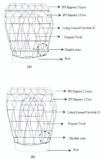
The finite element models investigated in this study are created for two types of models, namely chamfer and shoulder models, depending on the shape of the prepared tooth near the root. It is intended to see the effects of the shape of the prepared tooth on the stress and strain distributions and the strength of the tooth (Figure 3.a-b). The models are redefined and meshed with 10-node 3 degrees of freedom (DOF) tetrahedral elements, resulting in 140350 elements with 198729 nodes for the chamfer model and 140317 elements with 198697 nodes for the shoulder model. The crown tooth components can be modeled accurately with the tetrahedral elements. Since the stress distribution near the root comes out to be more critical, a larger number of elements were used for this region in the crowned tooth model. In the finite element model, the optimum element sizes used to obtain accurate results when the models were meshed (Figure 4).
2.2 Material properties
The crowned tooth consists of four components as shown in Figure 3: • Prepared tooth
• Substructure (IPS Empress 2 Core) • Ingot (IPS Empress 2 Layer) The following assumptions are made [12,13]:
a. The effect of the pulp is neglected since its Young' s modulus is very low (Table 1).
b. The influence of the peridontal ligament on the stresses in the crown is negligible because of its low thickness..
c. The materials are assumed to be isotropic and linearly elastic. The anisotropy of the crown and the tooth was not considered. However, because of the structure, the mechanical properties of tooth do vary with orientation and location
d. The bone is taken as rigid.
e. The distribution of the temperature during the processing of the crown is uniform. The modulus of elasticity and the Poisson ratio are constatnt because these properties are temperature dependent.
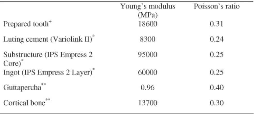
Table 1 presents the mechanical properties of the considered materials in this study.
In this study, IPS Empress 2 crown material is used as a restorative material. A new system for manufacturing porcelain crowns, called Empress 2, has developed a method of creating crowns that are almost indistinguishable from natural teeth. They are made out of porcelain without the metal support allowing for a natural translucent appearance. Of great current interest is the IPS Empress 2 crown for anterior teeth, because of its great beauty and translucency. The IPS Empress 2 system, which is based on moulding heated ceramic to reproduce accurate ceramic copies of wax models, has been around since 1990s'. This material does not require metal underneath to support and strengthen it. The results obtained from clinical research of this system are very promising. The IPS Empress 2 system is designed primarily for single unit restorations [14, 15].
Table 1. Material properties used in finite element models
Young's modulus Poisson's ratio (MPa)
Prepared tooth+ 18600 0.31
Luting cement (Variolink II)* 8300 0.24
Substructure (IPS Empress 2 95000 0.25
Core)*
Ingot (IPS Empress 2 Layer)* 60000 0.25
Guttapercha** 0.96 0.40
* The physical properties of each material were supplied by the companies. + [21]
** [22]
Variolink II (Ivoclar-Vivadent, Schaan, FL) is chosen as a luting material. The luting cement (Variolink II) thickness, between the restoration and the prepared tooth is taken as 0.025 mm. The first crown layer, namely IPS Empress 2 Layer is of 0.3 m m thickness, and is placed on the second crown layer, IPS Empress 2 Core. The lateral distance between these two layers ranged from 1 m m to 1.8 m m (Figure 2).
2.3 Boundary conditions:
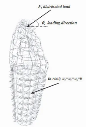
The loading direction angle is also considered to be of great importance. To simulate the in vivo situation, the different load directions are taken into consideration, namely 30o, 45o, 60o, and 90o [16, 17]. A calculation is done with bite forces as load. Both models are subjected to 200 N as distributed load, which is the maximum biting force [13, 18, 19]. The bite force is distributed uniformly on the points of the crown contact in occlusion perpendicular to the surface. The models are constrained in the root of the tooth as shown in Figure 4.
3. RESULTS
Knowledge of factors, which affect stress and its distribution, is of importance to the successful production of durable ceramic restorations. In this study, two different models are developed in order to show the effect of geometry on the
stress distribution. These are chamfer and shoulder models. Four types of loading conditions are investigated to see the effects of the loading direction on the each layer and restored tooth. All numerical analyses are performed for linear static loading condition.
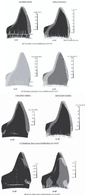
In this study, maximal principal stress, maximum shear stress and Von Mises equivalent stress are calculated. The calculated numeric data of stress and displacement on the each layer are visualized in graphics. Figures show the stress and strain distribution in terms of colored patterns. The values at the right hand side give the range of the values represented by that unique pattern. Figures 5 show the stress and strain distribution occurred in the tooth for various loading directions. As can be seen in the figures, the maximum stress occurs in the region where the load is applied independent of the loading direction in both models. This situation can be explained by the Saint-Venant's Principle. According to the Saint-Venant's Principle, the maximum stress greatly exceeds the average stress near the point of application of the load [20]. Figure 6-a shows the Von-Mises stress distribution in each layer. As shown in the figure, Von-Mises stress value is minimum in every layer when the force angle is 90o. Maximum stress occurs in IPS empress 2 core both for chamfer and shoulder model independently of the force angle. Maximum stress occurs at an angle of 30o about the horizontal axis, due to the moment caused by horizontal the component of the force about the tooth root.
Maximum principal stress distribution is seen in Figure 6-b. When this stress component is examined, it is seen that maximum stress occurs at an angle of an 30o for the chamfer model, but at an angle of 45o for the shoulder model. Maximum stress occurs in IPS Empress 2 Core as Von-Mises stress. When the force angle is 90o, IPS Empress 2 Layer at shoulder model is subjected to compression and the value of this compressive stress is 18.8 MPa. Maximum principal stress values in the dentin and luting cement (Variolink II) are relatively close to each other.
Figure 6-c shows the maximum shear stress distribution. As shown in the figure, maximum shear stress occurs in IPS Empress 2 Core as 48.8 and 48 MPa for chamfer and shoulder models, respectively. There is a similar tendency for the Von-Mises stress distribution. It can be concluded that stress components increase for shoulder model as the force angle decreases.
00
Figure 3. Components of (a) Model 1 and (b) Model 2
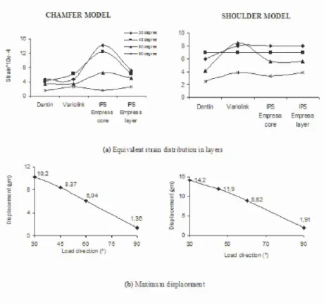
Equivalent strain distribution in each layer is seen in Figure 7-a. In contrast to the stress condition in the layer, maximum strain is in the luting cement (Variolink II ) and the strain value reaches to about 0.085% for shoulder model. But maximum strain occurs in the IPS Empress 2 Core for the chamfer model and the strain value reaches to about 0.145%. Minimum strain occurs at angle of 90o.
F; distributed load
Figure 4. Boundary conditions
Figure 7-b illustrates the effect of the force angle on the displacement of tooth. Maximum displacement occurs in the region where the force is applied. As seen from the figure, displacement increases as the force angle decreases. Maximum displacements are about 10 |im and 1 |im for 30o and 90o, respectively at the chamfer model and about 14 | m and 2 | m at the shoulder model.
Figures 8.a-d show the effects of the shape of the prepared tooth on the stress-strain distribution occured in the layers. Fig. 8-a shows the comparison of Von-Mises stress distribution. This figure is drawn for 30o in the critical case where maximum Mises stress occurs. As shown in the figure, the Von-Mises stress value in the shoulder model is greater than that in chamfer model when the IPS empress 2 Core is considered. However, Von-Mises stress in all layers of shoulder model is higher than that of the chamfer model.
The comparison of the maximum principal stresses can be seen in Figure 8-b. The Figure accounts for a force angle of 45o. These stress component values in
all layers of shoulder model are relatively higher due to the stress concentration zone. Stress concentration is caused by geometrical discontinues in this model.
Figure 8-c compares the maximum shear stress distribution for the two models. This figure is drawn for 30o. Similar results are obtained as in the case of maximum principal stress.
Equivalent strain distribution in each layer is presented in Fig. 8-d. This figure is drawn for 60o because the maximum strain occurs in loading case at this angle. Strain values are greater in dentin, Variolink II and IPS Empress 2 layer of shoulder model than those of the chamfer model. Maximum strain is measured in the IPS Empress 2 Core of the chamfer model as in the Von-Mises stress.
4. DISCUSSION
Dental biomechanics could be investigated more easily and more thoroughly by finite element analysis. Finite element technique is a powerful tool for biomechanical research. Failure modes are identified with the finite element method. The validity of finite element results must be compared with other engineering calculations or experimental results. The load needed to fracture crowns for shoulder and chamfer models could be found clinical investigation. Then, the results obtained could be compared with each other.
Crown performance is dependent many variables which can be controlled by the clinician in designing the crown system and patient dependent variables such as the crown material, luting cement type, amount of tooth reduction, load position remaining tooth structure. Not surprisingly, the choice of crown material and crown thickness has a great influence on the stress distribution. Interactions between variables can influence strength characteristic of crowned tooth. Perhaps because doing so would indicate evaluation of a large number of specimens. High cost of large numbers of experimental specimens is eliminated using finite element method. In this study, three-dimensional models were constructed to more closely simulate a crowned tooth. Theoretically the best finite element model would be a three dimensional model, which would accurately describe the three dimensional geometry of the prepared tooth and crowned tooth. In this study, it was assumed that the interface between the cement layer and other structures had no gap in the modeling the cement layer. If the modeling of the thin layer of cement was omitted, the actual stress values can be affected considerably. A three dimensional model allows for division into finer meshes.
CHAMFER MODEL SHOULDER M ODEL
9=3(P 6=30» Stress concentration zone
a) Von-Mises stress distributions for 6=30»
&=45' 6=45»
b) Maximum principal stress distributions for 9=45°
CHAMFER MODEL SHOULDER MODEL
Figure 5. Stress and strain distribution for different force angle at the chamfer and
CHAMFER MODEL Dentin Vafbliri< Errpress Errpress core layer SHOULDER M O D I ! IRS Empress IRS Errpress layer
(a) Von-Mises stress in layers
v 90 i £L 5 50 -I 1= 33 • J 23-£ 10
-Vsrblirk IRS IPS
Errpress Errpress core layer
Dentin Var ¡dirk IPS
Ehrpr es s Emptes s
core lay e
(b) Maximum principal stress in layers
Vaj-ioinfi IPS IPS Empress Errpress
core layer
IPS IPS Errpress Errpress
care layer
(e) Maximum shear stress in layers
Figure 6. Comparison of the different stress components in chamfer and shoulder
Figure 7. Comparison of the deformations in chamfer and shoulder model
This study focused on effect of the shape of prepared tooth on the strength characteristics of the crowned tooth. For this investigation, Empress 2 was chosen as crown material. However many variables was not considered. These variables may be critical in the design of new material. Future investigations need to geometry of actual tooth anatomy, failure damages, flaw density, crown material and thickness and load position.
5. CONCLUSIONS
Within the results of this study, the following conclusions are drawn:
> Maximum Von-Mises stress occurs in IPS Empress 2 Core both chamfer and shoulder model irrespective of the force angle. Maximum Von-Mises stress occurs at an angle of 30o about the horizontal axis, due to the moment caused by horizontal component of the force about the tooth root.
a) E = 120 m 8 80 CO . İ Ü 4 0 s 5 3 b)
ra
c_ S SO -, i5J -Iii 40 -Q. O 20 -CL Fİİ n -ire İRS Bmprss Enpress core layer IPS Enpress core IPS Ejnrpress layer d) eo « 20 D i ^-D=ntln VsfinJink IPS IFS
Eures i Enrpress
cor = lays
DEntir Vari^lrk FS IPS
Bmpfe i Bipr^i
c cr€ lay-et
> Maximum principal stress occurs in IPS Empress 2 Core as Von-Mises stress.
> There is a similar tendency in the maximum shear stress distribution as in Von-Mises stress distribution.
> Maximum strain occurs in the loading case at 60o. Strain values are greater in dentin, Variolink II and IPS Empress 2 Layer of shoulder model than those of the chamfer model.
This study demonstrated the relatively significant stresses that were involved in the chamfer and shoulder models. The results obtained by the Finite Element Analyses present that stress values increase when the loading angle decreases. In addition, the shape of the prepared tooth is an important factor in the stress distribution. Higher stresses were recorded with shoulder design compared to the chamfer design. It can be concluded that chamfer model should better be preferred for a good crowned tooth design.
For the interpretation of the results of this study one has to consider that clinically placed crowns might differ meaningful from the FEA models. In FEA models are not usually really representations of the structure because of assumptions. In fact, the physical characteristics of tissues vary from site to site and from individual to individual. The dimensions of natural restored tooth and mechanical constraints may change. Despite these limitations, the present study may be regarded meaningful representations of clinical trends.
As to clinical significance, the result of the present study would allow clinicians to make an informed choice from geometry of the region near the tooth root.
Acknowledgements
The authors want to thank to Prof. Dr. Mubin Ulusoy and Dt. Bilkay Karaman (Ege University, Dept. of Prosthetic Dentistry) for their helps and supports.
REFERENCES
[1] www.dentalfox.com
[2] DeHoff, P.H., Anusavice, K., and Gotzen, N.; Viscoelastic finite element analysis of an all-ceramic fixed partial denture, Journal of Biomechanics (2006), 39, 40-48. [3] Jager, A.D., Pallav, P., and Feilzer A.J.; The influence of design parameters on the
FEA-determined stress distribution in CAD-CAM produced all-ceramic dental crowns, Dental Materials(2005), 21, 242-251.
[4] Jager, A.D., Kler, M., and Zel, J.M.; The influence of different core material on the FEA-determined stress distribution in dental crowns, Dental Materials (2006), 22, 234-242.
[5] Lanza, A., Aversa, R., Rengo, S., Apicella, D.,and Apicella, A.; 3D FEA of cemented steel, glass and carbon posts in a maxillary incisor, Dental Materials (2005), 21, 709-715.
[6] Rekow, E. D., Harsono, M., Janal, M., Thompson, P., and Zhang, G., Factorial analysis of variables influencing stress in all-ceramic crowns, Dental Materials(2006), 22, 125-132.
[7] Sorrentino, R., Aversa, R., Ferro, V., Auriemma, T., Zarone, F., Ferrai, M., and Apicella, A.; Three dimensional finite element analysis of strain and stress distributions in endodondically treated maxillary central incisors restored with different post, core and crown materials, Dental Materials(2006),Article in press.
[8] Zarone, F., Sorrentino, R., Apicella, D., Valentino, B., Ferrari M., Aversa, R., and Apicella, A.; Evaluation of the biomechanical behaviour of maxillary central incisors restored by means of endocrowns compared to a natural tooth: A 3D static linear finite element analysis, Dental Materials (2006), 22, 1035-1044. [9] Rudolph, D. J., Willes, M. G., and Sameshima, G. T.; A finite element model of
apical force distribution from orthodontic tooth movement, Angle Orthodontist (2001), 71, 127-131.
[10] Aykul, H., Toparlı, M., and Dalkız, M.; A calculation of stress distribution in metal-porcelain crowns by using three-dimensional finite element method, The Journal of Oral Rehabilitation (2002), 29, 381-386.
[11] Pekbey, Y.; Stress analyses of a single crowned tooth with different materials, M.Sc. Thesis. Dokuz Eylul University (2002), Izmir, Turkey.
[12] Ausiello, P., Apicella, A., Davidson, C.L., and Rengo, S.; 3D-finite element analyses of cusp movements in a human upper premolar, restored with adhesive resin-based composites, Journal of Biomechanics (2001), 34, 1269-1277. [13] Yaman, S.D., Şahin, M., and Aydın, C.; Finite element analysis of strength
characteristics of various resin based restorative materials in Class V cavities. Journal of Oral Rehabilitation (2003), 30, 630-641.
[14] Neiva, G., Yaman, P., Dennison, J., Razzog, M. E., and Lang, B. R.; Resistance to fracture of three all-ceramic systems, Journal of Esthetic Dentistry (1998), 10(2), 60-66.
[15] Tidehag, P., and Gunne, J.; A 2-year clinical follow-up study of IPS Empress ceramic inlays, The International Journal of Prosthodontics (1994), 8 (5), 456-460.
[16] Nakamura, T., Imanishi, A., Kashima, H., Ohyama, T., and Ishigaki, S.; Stress analysis of metal-free polymer crowns using the three-dimensional finite element method The International Journal of Prosthodontics (2001), 14,401-405.
[17] Troedson, M., and Derand, T.; Effect of margin design, cement polymerization, and angle of loading on stress in porcelain veneers, The Journal of Prosthetic Dentistry (1999), 82 (5), 518-524.
[18] Hwang, W.J., and Yang, J.; Fracture strength of copy-milled and conventional In-Ceram crowns, Journal of Oral Rehabilitation (2001), 28, 678-683.
[19] Arabaci, Z.; An investigation of stress effects in human tooth crowned with various materials by using finite element method, M.Sc. Thesis. Dokuz Eylul University (2003), Izmir, Turkey.
[20] Ugural, A.C., and Fenster, S.K.; Advanced Strength and Applied Elasticity. 3rd Edition, Prentice-Hall Inc. New Jersey (1995).
[21] Farah, J. W., Dennison, J. B., and Powers, J. M.; Effects of designing on stress distribution of intracoronal gold restorations, Journal of American Dental Association (1997), 94,1151.
[22] Joshi, S., Mukherjee, A., Kheur, M., and Mehta, A.; Mechanical performance of endodontically treated teeth, Finite element analysis and design (2001), 37, 587-601.
[23] Ash, M.M.; Wheeler's Atlas of tooth form, W. B. Saunders Company, USA (1984).