Dergi web sayfası:
www.agri.ankara.edu.tr/dergi www.agri.ankara.edu.tr/journalJournal homepage:
TARIM BİLİMLERİ DERGİSİ
—
JOURNAL OF AGRICUL
TURAL SCIENCES
22 (2016) 444-454
Comparison of Energy Efficiencies of a Small Centrifugal Pump at
Constant and Variable Speed Operations
Selçuk ARSLANa, Alaa Abdulradha SAHİBb
aUludag University, Faculty of Agriculture, Department of Biosystems Engineering, Bursa, TURKEY
bKahramanmaras Sutcu Imam University, Institute for Graduate Studies in Science and Technology, Department of Bioengineering and
Sciences, Kahramanmaras, TURKEY ARTICLE INFO
Research Article
Corresponding Author: Selçuk ARSLAN, E-mail: [email protected], Tel: +90 (224) 461 16 06 Received: 02 March 2015, Received in Revised Form: 11 June 2015, Accepted: 11 June 2015
ABSTRACT
The objective of this study was to compare the energy efficiencies of flow rate valves used in different lines and variable speed drive (VSD) in a small centrifugal pump irrigation system. The tests were done by using an outlet valve, inlet valve, by-pass valve, and VSD. The study included four replications of constant speed and variable speed experiments, and three replications of constant pressure experiments. In each test, power consumption, inlet pressure, and outlet pressure were measured at different flow rates. During the constant speed tests at about the operating point, by-pass valve saved energy up to 66% and 5% compared to the outlet valve and inlet valve, respectively. Reducing the flow rate by 20% resulted in 7% less energy consumption with the use of both the by-pass valve and the inlet valve, and 19% more energy consumption with the outlet valve. The use of VSD showed profound advantage over the valves used in constant speed tests, with 41%, 44%, and 80% less energy demand compared to the by-pass, inlet, and outlet valve, respectively. Also, VSD and by-pass valves were compared in constant pressure operations. VSD offered 2 to 37% less energy consumption at pressures from 4.0 bar to 2.5 bar. The savings were less at high flow rates and quickly increased as the flow rate need decreased. The low system efficiency found in constant speed tests suggested that the pump was not appropriate for the hydraulic system used in low pressure applications. According to constant pressure tests, the system efficiency for VSD (26-29.1%) was greater than that of the by-pass valve (21.3-25.5%). In conclusion, the VSD was the most energy efficient method and suggested significant energy savings in small powered pump systems.
Keywords: Centrifugal pump; Irrigation; Power consumption; Energy efficiency; Variable speed drive
Küçük Bir Santrifüj Pompanın Sabit ve Değişken Hızlı Çalışma
Koşullarında Enerji Etkinliğinin Karşılaştırılması
ESER BİLGİSİ Araştırma Makalesi
Sorumlu Yazar: Selçuk ARSLAN, E-posta: [email protected], Tel: +90 (224) 461 16 06 Geliş Tarihi: 02 Mart 2015, Düzeltmelerin Gelişi: 11 Haziran 2015, Kabul: 11 Haziran 2015
1. Introduction
Different reasons can motivate a farmer to vary the flow rate to irrigate plants in specific fields. The need to vary the flow rate or pressure may arise from irrigating different field or field segment sizes using the same pump station. When the same pump is to be used in different fields, the static head may differ due to variations in topography. In this type of operation the flow rate needs to be maintained while pressure head varies. Warmer days during the irrigation season may require more water than the early growth stages of the plants. And in this type of operation, the pressure should be constant whereas flow rate varies. Since many fields have varying elevations and different sizes with multiple blocks to be treated, irrigation systems do not require constant pressures (ITRC 2011) or flow rates.
In automated systems incorporating moisture sensors to manage irrigation, the flow rate needs to be variable, too. Variable rate irrigation systems are used to apply different amounts of water to different zones in the fields (LaRue 2011) and may be used with various sensors with integrated wireless communication systems as well (Coates & Brown 2005; Han et al 2009). In such systems, the flow rate adjustment needs to be done by varying
the pump speed automatically. Using valves is the common method of varying the flow rate in small scale irrigation systems. In most applications, flow rate control is done by using a valve either on the suction line, pressure line, or by-pass line without using the speed control of the pump impeller.
Although the modernization of irrigation techniques improves water use efficiency, the pressurized pipes result in substantial energy use in agriculture, increasing the concern for energy savings and sustainability (Rocamora et al 2013). For instance in drip irrigation water efficiency, evaporation, and runoff are minimized and water efficiency may be up to 80 to 90% (Provenzano 2007). When pumping station efficiency is considered, however, there seems to be opportunities for improving the overall energy efficiency during irrigation. In central California, data from 15000 electric irrigation pumps showed that great number of the pumps operate inefficiently (Urrestarazu & Burt 2012). Thus, official administrations promote initiatives to improve energy efficiency in irrigated agriculture, and researchers are opt to develop different tools to achieve more energy efficient delivery of the irrigation water (Rocamora et al 2013). In some countries, agricultural energy conservation ÖZET
Bu çalışmanın amacı, küçük bir santrifüj pompanın kullanıldığı sulama sisteminde farklı hatlarda kullanılan debi ayar vanalarının ve değişken hızlı sürücü (DHS) kullanımının enerji etkinliğinin karşılaştırılmasıdır. Testler; emme vanası, basma vanası, by-pass vanası ve değişken hız kontrolü kullanılarak gerçekleştirilmiştir. Denemeler; sabit debi ve değişken hız şartlarında dört tekrarlı, sabit basınç çalışma koşullarında üç tekrarlı yapılmıştır. Her bir testte, farklı debilerde güç tüketimi, emme basıncı ve çıkış basınçları ölçülmüştür. İşletme noktasındaki sabit hız testlerinde by-pass vanası, çıkış vanasına ve giriş vanasına göre sırasıyla % 66 ve % 5 daha fazla enerji kazancı sağlamıştır. Debinin % 20 azaltılması, by-pass ve giriş vanası kullanıldığında enerji tüketimini % 7 azaltırken çıkış vanasında % 19 artırmıştır. DHS kullanımı; sabit hız testlerinde kullanılan by-pass, giriş ve çıkış vanalarına göre % 41, % 44 ve % 80 daha az enerji kullanımıyla çok önemli avantaj sağlamıştır. Ayrıca, DHS ile by-pass vanası sabit basınç testleri ile karşılaştırılmıştır. DHS 4.0 bar ile 2.5 bar arasında % 2 ile % 37 arasında enerji kazancı sağlamıştır. Enerji kazancı, yüksek debilerde daha az iken debi gereksinimi düştükçe kazanç hızla artmıştır. Sabit devir testlerinde bulunan düşük sistem verimi, kullanılan pompa ve hidrolik sistemin küçük basınçlı çalışmalar için uygun olmadığını göstermiştir. Sabit basınç testlerine göre, DHS’nün sistem verimi (% 26-29.1), by-pass vanasından (% 21.3-25.5) daha yüksektir. Sonuç olarak, DHS enerji yönüyle en etkin yöntemdir ve küçük debili sistemlerde önemli oranda enerji kazancı sağlayabilmektedir.
Anahtar Kelimeler: Santrifüj pompa; Sulama; Güç tüketimi; Enerji etkinliği; Değişken hız kontrolü
programs primarily focus on improving the energy efficiency of the pumping plants (ITRC 2011).
Pumping costs can be minimized by focusing on areas such as irrigation scheduling, application efficiency, efficiency of the pumping plant, and the pressure required for the system (Martin et al 2010). The main areas for energy conservation regarding the pumping station include controlling the flow rate by speed variation, eliminating flow control valve, and eliminating by-pass control (UNEP 2006). However, using the flow rate valves has been the most common method of varying the flow rate and the majority of today’s farmers use a flow rate valve installed either at the outlet (discharge) line or at the inlet (suction) line to vary the flow rate. In most countries, only a few percentages of the farmers practice the use of by-pass valves in irrigated agriculture and most pumping stations lack adjustable speed drives.
When energy consumption is considered, the best method of reducing energy consumption is the variable speed control of the pumps to meet varying demands since a slight reduction in speed can result in a significant reduction in input power (NRCS 2010). The improvement of pumping system performance depends on VSD (Sobhy et al 2011). Energy savings could be up to 35% by installing VSDs to pumping stations (Barutçu et al 2007; Lamaddalena & Khila 2012). Instead of using a valve to reduce the flow rate, reducing the pump impeller speed by 20% can reduce input power requirements by approximately 50% under certain conditions (Boyadjis 2004). Power demand from water pumps in big pumping stations may also be dropped by 40%. Reduction in the energy consumption in irrigation networks is also possible through functional programming and scheduling (Carrillo Cobo et al 2011).
The general objective of this study was to determine the energy efficiency of a small centrifugal pump under different operating conditions. The specific aim was to conduct constant speed, variable speed, and constant pressure experiments to determine the differences in the energy consumptions among different methods of varying the flow rate, including
the use of an outlet flow rate valve, inlet flow rate valve, by-pass valve, and VSD (Sahib 2014).
2. Material and Methods
2.1. Material
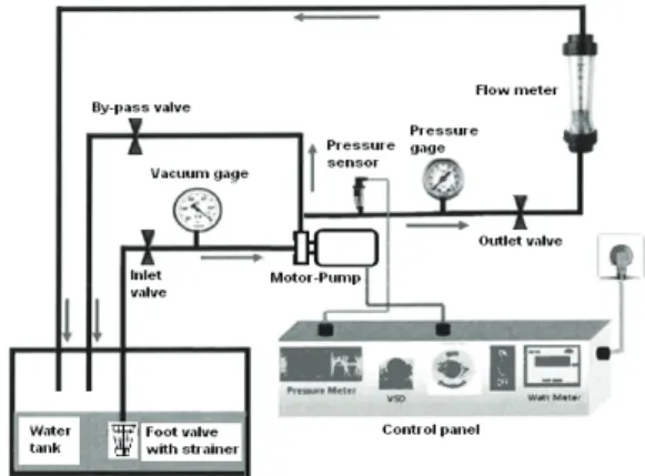
The experiments were conducted on a centrifugal pump test bench (Figure 1). The test system includes a water tank, foot valve with suction strainer, vacuum meter, inlet flow rate valve, a centrifugal pump, check valve, flow rate valve, an analog manometer, an outlet pressure sensor, inline flow meter (rotameter), and a control panel consisting of a wattmeter to measure the power consumption. Measurement ranges and the resolutions of the manometer (Aterma En837-1), pressure sensor (Gems 0-6 bars G) , inline flow meter (LZS-32), and the wattmeter were 0-6 bar with 0.1 bar, 0-6 bar with 0.01 bar, 0.6-6 m3 h-1 with 0.2 m3
h-1, and 0-9999 W with 1 W, respectively. Random
measurement error was not more than 0.05 bar and 0.1 m3 h-1 respectively, for the manometer/vacuummeter
and the inline flow meter.
Figure 1- Schematic of the centrifugal pump system used in the study
Şekil 1- Araştırmada kullanılan santrifüj pompa sisteminin şematik görünümü
Hm-Q curve of the pump is given in Figure 2. The rotational speed of the pump is 2900 rpm with a maximum head of 70 m with a flow rate of 50 L min-1 (3.0 m3 h-1).
Figure 2- Flowrate-head curve of the pump used in the study (City Pump 2014)
Şekil 2- Araştırmada kullanılan pompanın debi-manometrik yükseklik eğrisi (City Pump 2014)
2.2. Methods
The tests were conducted under three categories: 1) Constant pump speed tests with the outlet valve,
inlet valve, and by-pass valve, 2) Variable speed tests with the VSD,
3) Constant pressure tests with the VSD and the pass valve.
In constant pump speed experiments, the tests started at the maximum pump speed and the flow rate was reduced from its maximum value of 3.0 m3 h-1 by 0.2 m3 h-1 decrement with each flow
regulating valve. During variable speed tests, the VSD was used to change the pump impeller speed from 2900 to 0 rpm, resulting in variable flow rates. Although the speed of the electrical motor can be estimated, it was not measured in this study, rather predetermined flow rates were supplied by fine tuning the potentiometer on the control panel to collect the relevant data. In some pumping applications, the pressure needs to be constant even if the flow rate needs to vary during the operation. For instance, in agricultural irrigation systems the pressure demand may be from 1.0 bar to 3.0 bar for drippers and from 2.0 bar to 4.0 bar or higher for sprinklers. Therefore, the tests in the third set of experiments relate to constant pressure operations with varying flow rates.
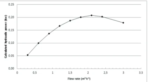
Constant and variable speed tests were replicated four times and constant pressure tests were repeated three times. Among the measured quantities, i.e. flow rate, inlet pressure, outlet pressure, and power consumption, only the flow rate and power consumption data were used in this paper. The averages of measured values were used for comparison purposes. The most energy efficient method was determined by comparing the power consumptions of different methods used for varying the flow rate. To do so, the hydraulic power delivered by the pump was calculated based on the data given in Figure 2. The efficiency curve was unknown, thus the hydraulic power curve was used to determine the flow rate at the operating point. The hydraulic power was calculated using the flow rate and head values of the pump provided by the manufacturer (Figure 3). The greatest power delivered by the pump was considered the best operating point, corresponding to about 2.2 m3 h-1. The test results were used to
compare the energy efficiencies for the operating point and also for about ±20% change in the flow rate, i.e. between 1.8 and 2.6 m3 h-1.
The system efficiencies were calculated and compared based on calculated hydraulic power and the measured total power needed for the constant speed, variable speed, and constant pressure operations.
Figure 3- Calculated hydraulic power based on flowrate-head curve of the pump used in the study Şekil 3- Araştırmada kullanılan pompanın debi-manometrik yükseklik eğrisine bağlı hesaplanan hidrolik güç değerleri
3. Results and Discussion
Systematic tests were conducted on a small powered irrigation pump to determine the energy efficient means of meeting the flow rate and pressure demands. The system had a small static lift (suction head of 0.6 m and discharge head of 0.85 m) along with a number of valves and elbows. Therefore, the measurements do not refer solely to the pump but to a small pumping station, consisting of some total static lift and losses due to the components used in the hydraulic system.
3.1. Constant pump speed tests
The power consumptions resulting from using an outlet valve, inlet valve, and by-pass valve to vary the flow rate were different. When the flow rate was reduced using the outlet valve, the discharge pressure of the pump increased remarkably, resulting in higher power consumptions at lower flow rates (Figure 4). The corresponding outlet and inlet pressures are shown in Table 1. The slope of the power consumption curve in Figure 4 suggested undesirable impact due to very rapid increase in the outlet pressure with decreasing flow rate.
With the use of the inlet valve to reduce the flow rate, the power consumption reduced gradually. However, the inlet vacuum pressure was somewhat high (-0.61 bar) even at the operating point and worsened (-0.70 bar) with a 20% decrease in the
flow rate, posing hazards regarding cavitations. Thus, in terms of suction line design, the inlet valve can be used to vary the flow rate, but only in a very limited range below the operating point. When energy consumption was considered, the inlet valve was advantageous compared to the outlet valve. The power consumptions were 1140 W and 409 W at the operating point, and 1354 W and 387 W for a 20% reduction in the flow rate, respectively for the outlet valve and the inlet valve. The inlet valve could be used safely at flow rates higher than the operating point since the vacuum demand kept decreasing accordingly (Table 1).
Table 1- Measured inlet and outlet pressures at different flow rates using flow regulating valves in different lines in the hydraulic system
Çizelge 1- Hidrolik sistemin farklı noktalarında debi ayar vanaları kullanılarak değişik debilerde ölçülen giriş ve çıkış basınçları
Flow rate
(m3 h-1) Outlet valve Inlet valve By-pass valve
Inlet pressure
(bar) Outlet pressure(bar) Inlet pressure(bar) Outlet pressure(bar) Inlet pressure(bar) Outlet pressure(bar)
3.0 -0.30 0.70 -0.30 0.70 -0.3 0.69 2.6 -0.23 3.46 -0.44 0.50 -0.3 0.55 2.2 -0.19 4.37 -0.61 0.33 -0.3 0.47 1.8 -0.12 4.96 -0.70 0.20 -0.3 0.25 1.4 1.0 -0.77-0.84 0.110.02 -0.3-0.3 0.130.05
Figure 4- The effect of outlet, inlet, and by-pass valves on the relationship between flow rate and power consumption in constant speed tests
Şekil 4- Sabit pompa hızında basma hattı, emme hattı ve by-pass vanalarının debi-güç tüketimi ilişkisine etkisi
Efficiency of a centrifugal pump usually decreases at a fast rate as the flow rate decreases. Additionally, electrical motor efficiency could reduce with increasing load on the motor. The back pressure on the pump due to the use of outlet valve could cause high loads on the electrical motor, drawing high current values resulting in a combined effect of low system efficiency. Therefore, the combined effect of low pump efficiency with low electrical motor efficiency should have resulted in excess power consumption during outlet valve adjustments, as shown in Figure 4.
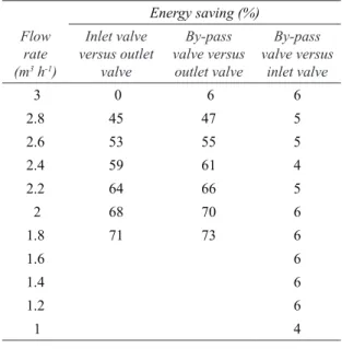
The least amount of power was consumed in the case of by-pass valve, compared to the outlet and inlet valves. The energy savings (%) were tabulated in Table 2 to compare the effect of the three valves. Compared to the outlet valve, the energy consumption at the operation point was 64% and 66% less in the inlet and by-pass valve tests, respectively. The energy efficiency increased further for 20% decrease in the flow rate.
Table 2- Per cent energy saving comparisons of flow rate valves in different lines at constant pump speed Çizelge 2- Sabit pompa hızında debi ayar vanalarının farklı noktalardaki yerleşiminin oransal enerji kazancı karşılaştırması Flow rate (m3 h-1) Energy saving (%) Inlet valve versus outlet valve By-pass valve versus outlet valve By-pass valve versus inlet valve 3 0 6 6 2.8 45 47 5 2.6 53 55 5 2.4 59 61 4 2.2 64 66 5 2 68 70 6 1.8 71 73 6 1.6 6 1.4 6 1.2 6 1 4
Table 2 demonstrates that compared to the operating point, the energy saving increased about 7% more, i.e.from 64% to 71% for 20% decrease in the flow rate using the inlet valve versus outlet valve. The additional saving in the case of by-pass valve was the same compared to the outlet valve.
The energy use for the inlet and by-pass valves seems to be similar in Figure 3, however by-pass valve was more energy efficient, about 4% to 6%, over the dynamic range of the flow rates tested (Table 2). Also, it was impracticable to reduce the flow rate using the inlet valve due to the rise in the suction pressure, from -0.6 to -0.7 bar. Therefore, even if the comparison is made only in terms of power consumption, the use of by-pass valve proves some advantage over the inlet valve. Since the by-pass valve did not increase the vacuum pressure (-0.3 bar) during the tests, it suggested a major advantage over the inlet valve.
Consequently, the location of a flow rate valve had a defining effect on energy efficiency. It was concluded that using an outlet valve was not an energy efficient method, which required the greatest power for operation. For a constant speed operation, i.e. when a VSD was not available on the pumping system, the best way of varying the flow rate was to use the by-pass valve. For a targeted flow rate, the outlet pressure need was a little lower with the inlet valve; however, the inlet pressure requirement was much higher. The overall effect of these two valves showed that the by-pass valve did not increase the vacuum pressure, minimized the potential suction line problems, decreased the outlet pressure, and needed the smallest energy requirement to vary the flow rate.
3.2. Variable pump speed tests
When all flow rate valves were open, decreasing the pump impeller speed from 2900 to 0 rpm reduced the power consumption due to the reduced major and minor losses in the hydraulic system (Figure 5). A gradual change was observed in power consumption in the VSD tests. The system had a small static lift, various valves, and elbows resulting in losses that affected the system behavior.
With no pressure demanding elements at the exit of the pipe system, the power consumption was about 100 W to 150 W at low flow rates. The power consumptions were 298 W, 230 W, and 177 W at flow rates of 2.6, 2.2, and 1.8 m3 h-1, respectively.
Reducing the flow rate by 20% provided 23.2% less energy compared to the operating point. The savings in energy were 5.5% and 6.1% for the inlet and the by-pass valve.
Figure 5- The effect of VSD on the relationship between flow rate and power consumption
Şekil 5- Değişken hız sürücüsünün debi-güç tüketimi ilişkisine etkisi
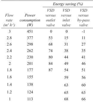
The energy use of VSD tests was compared to the constant speed tests (Table 3). Energy savings of VSD were 80%, 44%, and 41% compared to the outlet valve, inlet valve, and by-pass valve at 2.2 m3
h-1. Additional 7, 10, and 10% energy savings were
calculated in favor of VSD with 20% reduction in the flow rate. Clearly, the VSD increased the dynamic range of the flow rates that can be adjusted without increasing the power consumption. As exclaimed in the previous sub-section, the most favorable method was to use the by-pass valve in the absence of VSD. Integrating the VSD system into the pumping station reduced the energy use further compared to the by-pass valve.
It was concluded that among the use of VSD, outlet, inlet, and by-pass valves, the most energy efficient method to vary the flow rate was the use of VSD since the desired flow rate could be obtained with the smallest energy consumption.
3.3. Constant pressure tests
In some pumping operations, the flow rate may need to be varied while the pressure needs to be constant. To simulate such operation conditions two tests were conducted in this part of the study. The first test was conducted by using the VSD to obtain certain pressure values (4.0, 3.5, 3.0, and 2.5 bar) at varying flow rates. The flow rate was adjusted by using the VSD to achieve desired pressure head at the outlet.
The power consumption decreased as the flow rate was reduced at given outlet pressure settings (Figure 6). The power consumption changed at a slow rate at a given pressure setting as a result of varying the flow rate. The power consumption behaved accordingly as the pressure was reduced step by step from 4.0 bar to 2.5 bar at a given flow rate setting. For instance, at 4.0 bar the power consumption decreased from 1000 W to 760 W with Table 3- Energy savings of VSD compared to the flow rate valves used in different lines of the system Çizelge 3- Değişken hız kontrolünün sistemin farklı noktalarına yerleştirilen debi ayar vanalarına göre enerji kazancı Flow rate (m3 h-1) Power consumption (W) Energy saving (%) VSD versus outlet valve VSD versus inlet valve VSD versus by-pass valve 3 451 0 0 -1 2.8 377 53 15 11 2.6 298 68 31 27 2.4 262 74 38 35 2.2 230 80 44 41 2 201 84 49 46 1.8 177 87 54 51 1.6 155 59 56 1.4 138 63 60 1.2 124 65 63 1 113 68 66
the flow rate reduction. Similarly, at a flow rate of 2.2 m3 h-1, the power consumption reduced from 940
W to 550 W as the pressure demand reduced from 4.0 bar to 2.5 bar.
Figure 6- The effect of VSD on the relationship between flow rate and power consumption in constant pressure tests
Şekil 6- Sabit basınç testlerinde değişken hız sürücüsünün debi-güç tüketimi ilişkisine etkisi
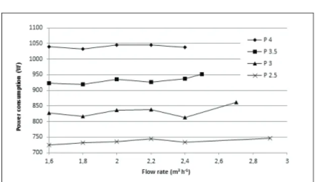
The second set of constant pressure experiments were conducted by adjusting the flow rate with the by-pass valve, instead of the VSD. The power consumption fluctuated and did not vary proportionally with the flow rate (Figure 7). It was interesting to note that the power consumption was almost the same at a given pressure setting. For instance, the average power consumption at 4.0 bar was 1039 W with the measured results ranging from 1033 W to 1045 W. This may be explained by the fact that the pump always operated at the maximum speed during the by-pass valve tests whereas the pump impeller speed was reduced step by step during the VSD tests.
The differences in the energy consumption between the VSD and by-pass valve corresponded to 2-27%, 5-30%, 3-35%, and 0-37%, respectively for 4.0, 3.5, 3.0, and 2.5 bar operations (Table 4). The energy consumption difference was low at high flow rates showing more opportunities to save energy as the flow rate needs to be lowered. Thus, the VSD was more advantageous compared to the by-pass valve for varying the flow rate at constant pressure applications as well.
According to literature, field experiments under different conditions resulted in 33% energy saving by using variable pump speed (Barutçu et al 2007) and power demand from the irrigation system dropped from 291 kW down to 175 kW, corresponding to 40% reduction in electric consumption for one pumping unit in a big pumping station (ABB 2013). In another study, installing VSDs to pumping stations resulted in 27% and 35% less energy consumptions in two different districts in an attempt to optimize energy consumption (Lamaddalena & Khila 2012). The energy savings were similar in the case of a small centrifugal pump, as shown in the current study. When there was a VSD in the system, energy savings at the operating point (2.2 m3 h-1) were 44% and 41% compared to
the inlet valve and the by-pass valve, respectively. Using the variable speed drive, 20% decrease in the flow rate further reduced the energy consumption by 10% compared to the operating point, making the VSD a very efficient means of flow rate regulation.
When the irrigation pump is not equipped with a VSD, an inlet valve could be used within a limited flow rate range, and a by-pass valve within a wider flow rate range compared to the use of an outlet valve. More than 60% of the energy could be saved at the operating point if a by-pass or inlet valve was used instead of an outlet valve. Furthermore, the energy saving of a by-pass valve was better (5%) than the inlet valve. Figure 7- The effect of by-pass valve on the relationship between flow rate and power consumption in constant pressures tests
Şekil 7- Sabit basınç testlerinde by-pass vanasının debi-güç tüketimi ilişkisine etkisi
Table 4- Energy saving comparisons between VSD and by-pass valve for constant pressure tests Çizelge 4- Sabit basınç testlerinde değişken hız kontrolü ile by-pass vanası arasında enerji kazancı karşılaştırması Outlet pressure (bar) Flow rate (m3 h-1) Power
consumption (W) Energy saving (%)
VSD By-pass valve VSD versus by-pass
4 2.4 1014 1038 2 2.2 936 1045 10 2 875 1045 16 1.8 812 1033 21 1.6 757 1040 27 3.5 2.6 950 952 0 2.4 887 937 5 2.2 818 926 12 2 738 936 21 1.8 689 920 25 1.6 651 924 30 3 2.8 838 861 3 2.4 734 814 10 2.2 688 838 18 2 616 836 26 1.8 575 817 30 1.6 540 828 35 2.5 3 758 746 -2 2.4 596 734 19 2.2 546 745 27 2 510 736 31 1.8 479 732 35 1.6 457 724 37
In the above discussion, the interpretation of the experimental power consumption values for the given operating conditions allowed to determine the least energy consuming flow rate control method. In a pumping system, the system efficiency is affected by both the input (total power consumed) and the output (hydraulic power). The use of outlet valve caused back pressures exerted on the pump impeller, which was the reason for observing high pressure values in the discharge line during constant pump speed tests. Accordingly, the hydraulic power of the pump was the highest for the outlet valve tests compared to the other
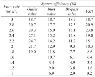
options. It seems misleading to note that the bigger hydraulic power obtained in outlet valve adjustments provided better system efficiencies (Table 5). The aim in these tests was to simulate unpressurized fluid flow and to supply the flow rate values with the minimum operational costs. For practical purposes, high pressure head was not needed but the ultimate effect of the outlet valve adjustment was to increase the power consumption profoundly compared to the other means of controlling the flow rate (Figure 4). When the inlet and outlet valves in constant speed tests were compared, the inlet valve was more efficient. This could be due to the fact that more energy is dissipated in order to pass the water through the pump and the by-pass line compared to the reduced mass flow through the pump in the case of inlet valve operation. When the inlet and by-pass valves were compared with the VSD, the system efficiency of VSD was higher and rapidly decreased with the reduction in the flow rate in all cases. Generally the system efficiency was low at constant and variable speed operations and were 14.1%, 11.2%, and 15.1% for the inlet valve, by-pass valve, and the VSD at 2.2 m3 h-1. These findings prove that the pump and the
hydraulic system do not match well for low pressure operations unless equipped with VSD.
Table 5- System efficiencies in constant and variable speed tests
Çizelge 5- Sabit ve değişken hız testlerinde sistem verimleri
Flow rate
(m3 h-1)
System efficiency (%) Outlet
valve valveInlet By-pass valve VSD
3 18.7 18.7 18.7 18.7 2.8 30.7 17.7 17.5 20.9 2.6 29.3 15.9 15.1 23.8 2.4 27.1 15.2 12.8 19.0 2.2 24.7 14.2 11.2 15.1 2 21.7 12.9 9.3 10.3 1.8 19.0 11.8 7.7 8.6 1.6 10.7 6.1 6.4 1.4 9.4 4.9 3.4 1.2 9.0 3.8 1.6 1 6.9 2.9 0.2
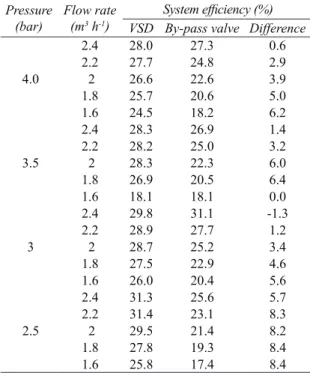
Constant pressure tests demonstrated better system efficiencies compared to the constant speed tests both for the by-pass valve and the VSD (Table 6). The calculated system efficiencies were roughly 20-27% and 25-30%, respectively for the by-pass valve and the VSD. More specifically, the system efficiency of the five different flow rates in Table 6 at 4.0, 3.5, 3.0, and 2.5 bar were 26.0-29.1% and 21.3-25.5%, respectively for the VSD and the by-pass valve. Eventually, the results were more favorable for the VSD operations and the degree of benefit in system efficiency depends on the pressure and flow rate demand. As expected, the system efficiency decreased with decreasing flow rate at a set value of outlet pressure. Based on the results and discussions, it may be argued that a constant speed pump cannot be operated over a wide flow rate ranges due to low efficiencies encountered as a result of changes in the flow rate. Therefore, in systems requiring wide dynamic flow rate ranges, it is best to install a VSD in the system.
Table 6- System efficiencies in use of the VSD and the by-pass valve in constant pressure tests
Çizelge 6- Sabit basınç testlerinde değişken hız sürücüsü ve by-pass vanası kullanımında sistem verimleri
Pressure
(bar) Flow rate (m3 h-1)
System efficiency (%) VSD By-pass valve Difference
2.4 28.0 27.3 0.6 2.2 27.7 24.8 2.9 4.0 2 26.6 22.6 3.9 1.8 25.7 20.6 5.0 1.6 24.5 18.2 6.2 2.4 28.3 26.9 1.4 2.2 28.2 25.0 3.2 3.5 2 28.3 22.3 6.0 1.8 26.9 20.5 6.4 1.6 18.1 18.1 0.0 2.4 29.8 31.1 -1.3 2.2 28.9 27.7 1.2 3 2 28.7 25.2 3.4 1.8 27.5 22.9 4.6 1.6 26.0 20.4 5.6 2.4 31.3 25.6 5.7 2.2 31.4 23.1 8.3 2.5 2 29.5 21.4 8.2 1.8 27.8 19.3 8.4 1.6 25.8 17.4 8.4
It was concluded that, the use of VSD should be the first preference followed by the use of a by-pass valve for varying the flow rate of a centrifugal pump. The use of a suction valve may be allowed for flow rates above the operating point but could be used very cautiously just below the operating point due mainly to rapidly increasing vacuum pressure in the suction line.
4. Conclusions
The followings could be summarized and concluded as result of this study. A small centrifugal pumping station was used to investigate the energy efficiencies of using flow rate valves in different lines and the VSD. When there was no VSD, the most energy efficient way to deliver different flow rates was to use the by-pass valve with 66% more energy saving than the outlet valve and 5% more than the inlet valve. The use of the inlet valve, albeit energy efficient compared to the outlet valve, could create suction line hazards. VSD provided the most energy efficient operations with 41% less energy consumption compared to the by-pass valve. As the flow rate demand of the irrigation system decreased, the VSD became even more efficient compared to the by-pass valve for regulating the flow rate. In constant pressure experiments, VSD provided 2% to 37% reductions in the energy consumption compared to the by-pass valve, depending on the pressure and flow rate demand. VSD technology should be favored because of its significant impact on increasing the energy efficiency in meeting different flow rate and pressure demands. If a VSD is not available, by-pass technique should be preferred over the inlet valve and outlet valve. The VSD provided better system efficiency compared to the by-pass valve during constant pressure operations, respectively with 26-29.1% and 21.3-25.5%.
References
ABB (2013). Case: Riecorfarming. 3AUA0000152416 REV A EN 15.11.2013. http://www.abb.com/drivespartners, pp. 1-4 (Access Date: 15 November 2013)
Barutçu F, Lamaddalena N & Fratino U (2007). Energy saving for a pumping station serving an on-demand
irrigation system: A study case. In: Water Saving in
Mediterranean Agriculture and Future Research Needs, eds. Lamaddalena N., Bogliotti C., Todorovic
M., Scardigno A. 56(1): 367-379
Boyadjis P (2004). Detecting a hidden lateral rotor natural frequency in a sewage pump, www. Pump-Zone.com, Pumps & Systems
Carrillo Cobo M T, Rodriquez Diaz J A, Montesinos P, Lopez Luque R & Camacho Poyato E (2011). Low energy consumption seasonal calendar for sectoring operation in pressurized irrigation networks.
Irrigation Science 29: 157-169
City Pump (2014). City Pumps. http://www.citypumps.it/ enter_gb.html (Access Date: 04 April 2014)
Coates R & Brown P (2005). Precision irrigation and fertilization in orchards. In: 2005 Annual International
Meeting, ASAE Paper Number: 052214, 17-20 July,
Tampa, Florida, pp. 1-16
Han Y J, Khalilian A, Owino T O, Farahani H J & Moore S (2009). Development of Clemson variable-rate lateral irrigation system. Computers and Electronics
in Agriculture 68(1): 108-113
ITRC (2011). Irrigation system components and potentials for energy conservation. Irrigation Training Research Center, California Energy Commission, Public Interest Energy Research (PIER) Program, ICTR Report No. R 11-003, pp. 32. http://www.ictr.org/ reports/components.html (Access Date: 27 July 2014) Lamaddalena N & Khila S (2012). Energy saving with
variable speed pumps in on-demand irrigation systems. Irrigation Science 30(2): 157-166
LaRue J L (2011). Variable rate irrigation 2010 field results for Center Plains Conference. In: Proceedings of the
23rd Annual Central Plains Irrigation Conference,
Burlington, CO., February 22-23, Available from CPIA, 760 N. Thompson, Colby, Kansas, pp. 135-143
Martin D L, Kranz W L, Dorn T W, Melvin S R & Corr A J (2010). Reducing the cost of pumping irrigation water. In: Proceedings of the 23rd Annual Central Plains
Irrigation Conference, Burlington, CO., February
22-23, Available from CPIA, 760 N. Thompson, Colby, Kansas, pp. 41-50
NRCS (2010). Variable Speed Drive (VSD) for irrigation pumping. Natural Resources Conservation Service, Engineering Technical Note No. MT-14, Montana, US, pp. 1-36
Provenzano G (2007). Using HYDRUS-2D simulation model to evaluate wetted soil volume in subsurface drip irrigation systems. Journal of Irrigation and
Drainage Engineering 133(4): 342-349
Rocamora C, Vera C & Abadia R (2013). Strategy for efficient energy management to solve energy problems in modernized irrigation: Analysis of the Spanish case. Irrigation Science 31: 1139-1158
Sahib A A (2014). Comparison of Energy Efficiencies of Constant and Variable Flow Rate Operations with a Small Scale Irrigation Pump. MSc Thesis, Kahramanmaras Sutcu İmam University Institute for Graduate Studies in Science and Technology, Kahramanmaraş, Turkey
Sobhy M G, Samir M A & Dalia M E (2011). Dynamic performance application of a variable speed centrifugal pump, In: Fifteenth International Water
Technology Conference, IWTC 15 2011, Alexandria,
Egypt
UNEP (2006). Electrical Energy Equipment: Pumps and Pumping Systems. In: Energy Efficiency
Guide for Industry in Asia. United Nations
Environment Programme. pp. 1-19. http://www. energyefficiencyasia.org (Access Date: 18 June 2014) Urrestarazu L P & Burt C M (2012). Characterization of
pumps for irrigation in central California: Potential energy savings. Journal of Irrigation and Drainage