PRODUCTION AND STRUCTURAL ANALYSIS OF Ti3AlC2/Ti3C2 INCORPORATED EPOXY COMPOSITES
1,2Derya KAPUSUZ
1Gaziantep University, Department of Metallurgical and Materials Engineering, 27310, Gaziantep, TURKEY 2Drexel University, Department of Materials Science and Engineering, 19104, Philadelphia, USA
(Geliş/Received: 13.01.2019; Kabul/Accepted in Revised Form: 11.03.2019)
ABSTRACT: Epoxy resins have been extensively used in a wide range of industrial applications owing to their superior properties like good electrical insulation, adhesiveness and high mechanical strength. They have moderate viscosity and curing temperatures lower than 200 °C, thus have been ideal candidates for protective coatings in electronic, aerospace and marine industries. In order to combine superior properties of epoxy with enhanced mechanical strength for bulk, structural applications, various nanomaterials including clays and graphite have been incorporated into epoxy resins. However, sufficient level of enhancement in mechanical strength and thermal resistance could not be provided due to excessive agglomeration of nanosized particles. Agglomeration limited the wettability of particles by the monomer, leading to decreased polymerization efficiency at the polymer-reinforcer interface. In this study, the aluminum layer in Ti3AlC2 (MAX (312); ternary carbides), was chemically etched leaving a layered structure possessing graphene-like electrical conductivity (Ti3C2) with good mechanical strength. Both, MAX and MXene were incorporated into epoxy monomer at identical ratios. The incorporation of Ti3C2 layers resulted in disappearance of (002) peak in XRD analysis. This indicated the delamination of MXene layers inside epoxy matrix. The glass transition temperature (Tg) of epoxy shifted from 175 to 180 C and 183 C by 4 wt. % incorporation of MAX and MXene respectively. The microhardness increased from 18.9
1.8 to 27.5 5 when 4 wt. % MXene, and to 20.6 2.9 when 4 wt. % MAX incorporated. This study indicates that it is possible to produce highly reinforced MXene/epoxy composites and use them in structural applications while the agglomeration is prevented.
Key Words: Layered carbide, epoxy, MAX, MXene, composite
Ti3AlC2/Ti3C2 Katkılanmış Epoksi Kompozitlerinin Üretimi
ÖZ: Epoksi reçineler, iyi elektrik yalıtımı, yüksek yapışkanlık ve mekanik mukavemet gibi üstün özellikleri sayesinde endüstride geniş bir uygulama yelpazesinde yaygın olarak kullanılmaktadır. Orta derecede viskoziteye ve 200 °C' nin altında kür sıcaklığına sahiptirler. Böylece elektronik, havacılık ve denizcilik endüstrilerinde koruyucu kaplamalar için ideal adaylardır. Epoksinin üstün özelliklerini yüksek mekanik mukavemet ile birleştirerek yapısal uygulamalarda kullanabilmek için killer ve grafit gibi çeşitli nanomalzemeler ile desteklenmiştir. Bununla birlikte, nano-boyutlu yapıların aşırı topaklanması nedeniyle mekanik özellikler ve ısıl dayanımında yeterli artış sağlanamamıştır. Topaklanma parçacıkların monomer tarafından ıslatılabilirliğini sınırlandırarak polimer matris ile destek parçacıkları ara yüzünde polimerleşme verimini düşürmüştür. Bu çalışmada, Ti3AlC2 (MAX 312) yapısında bulunan alüminyum (Al) tabakası dağlanarak grafen benzeri iletkenliğe sahip 2-boyutlu Ti3C2 tabakaları (MXene) elde edilmiştir. Her iki yapı, MAX ve MXene, eşit oranlarda epoksi monomerine katkılanarak polimerleştirilmiştir. mL- (çok tabakalı) MXene katkılanan numunelerin XRD analizlerinde (002) pikinin kaybolduğu görülmüştür. Bu durum, MXene tabakalarının delamine olduğunun göstergesidir. Ağ. %4 oranında MAX ve MXene katkılandığında epoksinin cam geçiş sıcaklığı (Tg) 173 C'den sırasıyla 180 ve
183 C’ye yükselmiştir. Ağ. %4 oranında MXene katkılandığında epoksi mikrosertliği 18,9 1,8 HV’den 27,5 5 HV’e, Ağ. %4 oranında MAX katkılandığında ise 20,6 2,9 HV’e yükselmiştir. Bu çalışma topaklanmanın önlenerek, yüksek katkılı MXene/epoksi kompozitlerinin üretilebileceğini ve yapısal uygulamalarda kullanılabileceğini göstermektedir.
Anahtar Kelimeler: Tabakalı karbür, epoksi, MAX, MXene, kompozit
INTRODUCTION
Epoxy resins are thermosetting polymers which contain two or more epoxide groups in their structure (Jin, Li, and Park 2015; May 1987). They can be produced via heat or light curing reactions using a broad range of curing agents (Jin, Li, and Park 2015). Until recently, owing to their low cost, ease of processability, adhesiveness, electrical insulation and thermal resistance, they have been used in various industrial applications including production of hardware components like integrated circuits, transistors or capacitors and as general-purpose protective coatings or structural glues in automotive, aerospace and marine applications (Liu et al. 2018; Wang et al. 2016).
Incorporation of inorganic particles such as nanoparticles, fibers, nano-clays and graphene toughened epoxy resins by particle bridging, crack path deflection and pinning mechanisms (Kumar and Roy 2018; Wang, Jin, and Song 2013; Li et al. 2017; Poonpipat et al. 2017; Yousri, Abdellatif, and Bassioni 2018). However, as the content of reinforcing fillers increased to enhance mechanical properties further, dispersion problems arose. Researchers showed that small amount of nano fillers could provide similar mechanical strength to that of conventional micro/macro fillers (usually required >10 wt. %) provided at higher ratios (Yousri, Abdellatif, and Bassioni 2018). Then by incorporating nanofillers, larger amount of particle surfaces could be wet by the epoxy monomer, leading to decrease in cured polymer chain mobility under stress. Accordingly, the thermomechanical properties were notably enhanced.
Among various nanofillers, influence of incorporating clays (Laouchedi, Bezzazi, and Aribi 2017) and carbonaceous materials (Choi 2013) (carbon fibers, graphite, graphene layers, etc.) into epoxy matrix were one step ahead. As clay layers were incorporated, they were dispersed in the matrix and monomer could wet the surfaces between the layers. The incorporation of clay (i.2 montmorillonite) layer stacks (intercalative) limited the mobility of polymer chains and led to increase in thermomechanical performance, dimensional stability, toughness and stiffness (Souza et al. 2014). Carbon fibers with high strength were incorporated into epoxy and composites were usually used more extensively in structural applications due to their superior specific stiffness and strength properties (Choi 2013). However, the entanglement of fibers, thereby aggregation in the matrix was a notable problem that needed to be addressed. Carbon nanotubes, having a nanoscale morphology combined with good conductivity, were also used for the reinforcement of epoxy. Similarly, they showed low dispersibility and weak mechanical interlock at the tube-epoxy matrix interface (Sowichai et al. 2012; Prolongo et al. 2013). Graphene, atomically thin layers of carbon, has superior surface area (2630 m2/g) and thermal conductivity (5000 W/m*s) (Rao et al. 2009; Kausar, Anwar, and Muhammad 2016). Owing to its good thermomechanical performance, epoxy/graphene composites were also produced. However, graphene layers started to aggregate in epoxy after 2 wt. % incorporation. It has been stated by many researchers that it is not possible to disperse graphene platelets in polymers including epoxy, without applying chemical functionalizations (Xu et al. 2012; Atif, Shyha, and Inam 2016; Radovic et al. 2011). In this regard, the need for epoxy nanofillers which allow for high loading percentages without agglomeration and provide clay morphology with carbon-like properties was undeniable.
MAX phases (Mn+1AXn, n=1,2 or 3) are a large family of layered, hexagonal early-transition-metal carbides/nitrides, in which M denotes for an early transition metal, A for an A-group (13 and 14) element and X for carbon (C) or nitrogen (N). MAX phases are ideal fillers for developing mechanically strong structural polymer matrix composites. They are elastically stiff and electrically and thermally conductive. They combine ease of machinability with excellent mechanical properties, especially at high temperatures
(>1000 °C) MXenes, on the other hand, are a large family 2 dimensional (2D) carbides/nitrides which are derived from MAX phases through wet chemical etching of A layer (Anasori, Lukatskaya, and Gogotsi 2017). They possess excellent electrical conductivity, a clay-like texture when intercalated with water and small ions, opening the door for a wide range of applications including molecular delivery and structural composites (Barsoum, 2013).
MXenes exhibit graphene-like electrical performance and layered morphology like clays, allowing to combine advantageous properties of graphene and clays. Compared to graphene, they offer wider range of properties on account of their surface terminations formed during or after etching. When incorporated in epoxy and well-dispersed, -OH, -O, -F terminations (Tx) can provide different properties and/or a strong mechanical interlock at the matrix-filler interface simultaneously. As the most commonly investigated MXene, Ti3C2-(Tx), has proven its electrical performance comparable to graphene, which is strongly related to its surface terminations (Anasori, Lukatskaya, and Gogotsi 2017).
Many critical questions related to epoxy-filler interface are required to be answered. Comparing the interface behavior of a strong carbide material at bulk and layered morphologies can be the first step to understand the influence of interface morphology on structure and to deliver enhanced thermomechanical behavior (Zaman et al. 2015). In this respect, this study involves the production of Ti3C2 MXenes through well-known lithium fluoride/hydrogen chloride (LiF/HCl) etching procedure from MAX phases. As-prepared etched powders were composed of Ti-C octahedral layers which were held into each other from one side, forming an accordion-like shape. This type of structure was referred to “multi-layered” (mL-) Ti3C2. mL-Ti3C2 particles were incorporated into epoxy matrix, structural properties, thermomechanical behavior and hardness of the composites were tested and compared with neat and Ti3AlC2 (MAX) incorporated epoxy.
This study is the first report to investigate and compare the microstructure and thermomechanical properties of Ti3AlC2 and Ti3C2Tx incorporated epoxy composites. It shows that viscous epoxy resins can be reinforced with mL- Ti3C2Tx and form exfoliated composites without agglomeration of the Ti3C2Tx layers in the epoxy matrix. Moreover, a scalable method combining mL-MXene washing, filtering and drying is reported for the first time in literature. The total time used for 2 g of MAX was 40 min at the longest, whereas it takes 100-120 min when centrifugal washing was performed.
MATERIALS AND METHODS Synthesis of Ti3AlC2 (MAX)
The typical route for the production of Ti3AlC2 particles were described previously (Ghidiu et al. 2014) (Naguib et al. 2011). Typically, commercially provided Ti2AlC and TiC powders were dry-mixed at stoichiometric ratio (1:1, molar) for 24 h using ball mills. After that, this powder mixture was sintered at 1350°C for 2 h under argon atmosphere. The sintered bulk sample was crushed, powdered and sieved to 200 mesh.
Etching of Ti3AlC2
In MAX phases, M-A bonds are chemically more reactive than M-X bonds, so that it is possible to leach Al layers between Ti-C layers (Poonpipat et al. 2017). For selective etching of Al layers, a well-understood etching method of MAX phases was followed (Ghidiu et al. 2014). Ti3AlC2 particles were poured into a LiF (Alfa Aesar) dissolved acidic aqueous solution. Typical etching solution contained 20 mL of aqueous HCl (6M). As LiF powders were dissolved completely in the acidic solution, Ti3AlC2 particles were added. The LiF: Ti3AlC2 molar ratio was kept as 1:5. The solution was stirred at ambient conditions (25±3 °C, 1 atm). Then, etching reaction was performed at 40 °C for 24 h under continuous stirring at 500 rpm. After the reaction was complete, the etched powders were separated from the acidic solution and washed using a vacuum-operated Buchner funnel system. In a typical washing procedure, 20 mL of etched solution was poured onto the filter paper (0.22 µm) placed in the Buchner funnel. First, the acidic liquid was separated from particles by vacuuming. The precipitates were collected on the filter
paper inside the funnel. Then, 250 mL of distilled water was poured inside the funnel in 50 mL volumetric parts (5x) and each 50 mL solution was refiltered for 5 min. Then, identical procedure was repeated for 100 mL of ethanol (99 %, 2x). After washing was completed, particles were vacuum-filtered until the supernatant pH reached 7.0 (≈20 min) and completely dried. Then, the particles were kept under vacuum until use. Using this simple, funnel washing strategy eliminated the centrifuging step and provided faster washing and separation of precipitated mL-Ti3C2Tx directly from the remaining acid solution and unwanted by-products.
Production of Ti3AlC2/mL-Ti3C2 Embedded Epoxy Composites
In a typical composite preparation procedure, certain amounts of Ti3AlC2 and Ti3C2 particles (Table 1) were added into 8 g of EPON 828® and mixed in a centrifugal mixer (Thinky® ARE-250) for 10 min at 2000 rpm, followed by 5 min of degassing. After homogeneous mixture was obtained, 2.24 g of PACM® (Amicure, bis-(p-aminocyclohexyl) methane) was added into the mixture and further mixed for 20 min at 2000 rpm, without degassing. The mixture was then transferred to the rubber mold and cured at 95 °C for 2 h, post cured at 160 °C for 2 h. Heat curing was performed under atmospheric conditions.
Characterization and Testing
Powder X-ray diffraction (XRD) analysis was performed on Ti3AlC2 and Ti3C2 particles and on MAX/MXene composite formulations given in Table 1. Prior to analysis, composites were ground to 200 mesh powders. XRD analyses were carried out by Rigaku X-ray diffractometer (Rigaku SmartLab®, Drexel University) in Bragg-Brentano mode using monochromatic Cu K-alpha rays (1.54056°A). The scan step was 0.04°/s and the powders were scanned at 2 theta of 5-65° at 1 s/° resolution.
Ti3AlC2, Ti3C2 particles and cross section surfaces of Ti3AlC2/Ti3C2 embedded epoxy composites were analyzed using scanning electron microscope (SEM, Zeiss Supra 50VP ®with EDS (Oxford), Drexel University). The operating voltage was 10 kV and samples were coated with 10 nm of platinum before analysis.
Thermomechanical strength of the Ti3AlC2/Ti3C2 embedded epoxy composites was tested using single cantilever measurement DMA system (TA Instruments®, Drexel University) with a heating rate of 5°C/min. Each sample was heated up to 300 °C.
A Vickers microhardness tester (AOB Test Systems®, Gaziantep University) was used to evaluate hardness of composites. Prior to tests, the surfaces were manually ground using 600 and 1000 grit SiC papers. In each test, 40 measurements were performed on top and bottom surfaces (20 per each surface) using 1 kg load with 10 s dwell time.
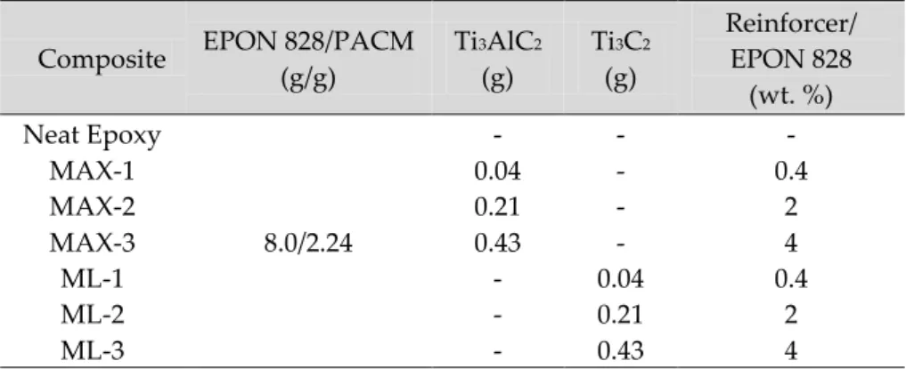
Table 1. MAX and mL-MXene reinforced composite formulations Composite EPON 828/PACM
(g/g) Ti3AlC2 (g) Ti3C2 (g) Reinforcer/ EPON 828 (wt. %) Neat Epoxy 8.0/2.24 - - - MAX-1 0.04 - 0.4 MAX-2 0.21 - 2 MAX-3 0.43 - 4 ML-1 - 0.04 0.4 ML-2 - 0.21 2 ML-3 - 0.43 4
RESULTS AND DISCUSSION
Structural Analysis of MAX and MXene
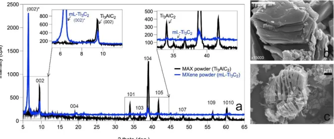
In Figure 1a, XRD pattern of Ti3AlC2 (before etching, MAX) is shown with that of mL-Ti3C2 particles (after etching, mL-MXene). Ti3AlC2 and mL-Ti3C2 morphologies are shown in Figure 1b-c. Ti3AlC2 (MAX) exhibited typical diffraction peaks at 9.52, 19.00, 34.12, 35.03, 36.72, 38.98, 41.66, 48.41, 56.41 and 60.80 corresponding to (002), (004), (101), (102), (103), (104), (105), (107), (109) and (1010) crystallographic planes, respectively (JCPDS #01-074-8806). After etching of the Al layers from the MAX structure, almost all of the (h0l) peaks disappeared as also observed by the previous researchers (Ghidiu et al. 2014). The intensity of (00l) peaks diminished/disappeared and a new, intense peak at 6.53 formed. Ti3AlC2 is composed of Al layers, which are sandwiched between the octahedral Ti3C2 layers. The diffraction of crystalline (00l) planes in the XRD pattern corresponds to the presence of these octahedral layers. As Al layers in MAX phase were eliminated by etching, the interplanar (d-) spacing between Ti3C2 layers increased, leaving an accordion-like morphology as shown in Figure 1c. This separation of layers is reflected to the XRD pattern as shifting of the (00l) peaks to smaller degrees in compliance with the Bragg’s Law, which states that the diffraction angle decreases by the increase in the d-spacing. This shifting is clearly observed in (002) plane. The newly formed peak at 6.53 is the shifted (002) peak after etching (referred as (002)*). The calculated “c” lattice parameter was 2.74 nm, which was identical to the one obtained by previously performed centrifugal washing (Ghidiu et. al. 2014). Considering an equivalent amount of increase must occur in interplanar spacing between (004) planes based on crystallographic principles, a shifted, less intense (004) peak was expected to present at angles smaller than 5. The positions of the remaining (h0l) peaks (i.e. (104)) on the other hand, were not shifted since they correspond to the inner crystal structure of octahedral layers.
In this etching and washing procedure that uses the Buchner Funnel, most of the (h0l) peaks were eliminated indicating that the procedure was an effective washing procedure to remove unreacted (or unetched) MAX from the solution. This study shows for the first time that funnel filtering is a time-efficient technique for high capacity-MXene washing and drying per unit time. In a completely etched structure, the (002) peak at 9.52 completely disappears (Ghidiu et al. 2014). Then, the presence of a small non-shifted (002) together with (104) peak after etching, indicate that Buchner funnel washing was effective on elimination of etched Al products from mL-MXene, but more prolonged time of reaction was required for complete etching of Al layers when MAX-to-LiF molar ratio of 1:5 is used. In the conventional washing procedure, the total time for washing, filtering and centrifuging to get dry mL-MXene was approximately 100 min. In the current study, using the Buchner funnel, etched MXene solution (containing unreacted LiF and by-products) could be washed, filtered and dried totally in 40 min. Moreover, the method can provide control of d-spacing (002) by intercalating more/less water between the layers during washing in the funnel. Controlling the d-spacing by changing the washing parameters can allow for delivery of various molecules within MXenes. The method prevented powder losses which occur in the conventional method upon solution transfer from tube to disposal during centrifugation.
Figure 1 a) XRD patterns of Ti3AlC2 (before etching)and Ti3C2 (after etching), and SEM images of b) Ti3AlC2 and c) Ti3C2 particles. Inset XRD patterns show the zoomed versions of the patterns in 2-theta of 5-12° range (left) indicating the shifting of the (002) from 9.52° to 6.53° ((002)*), and in 2-theta of 33-45°
range (right) indicating the disappearance of (h0l) peaks. Structural Analysis of the Composites
As shown in Figure 1b-c, the MAX particles are bulk, chunky particles containing Al between Ti3C2 layers, whereas mL-Ti3C2 particles are accordion-like structures in which the layers are attached to each other on one side, containing large spaces in between. Incorporating these materials separately into epoxy monomer using an identical procedure can reveal the efficiency of epoxy chain and the Ti3C2 layer interaction at the interface and final composite properties can be analyzed comparably.
There are two important structural concerns about layered composites in literature, which are the delamination and the agglomeration of the fillers. Delamination on one hand, can provide strong mechanical interlock leading to enhanced degree of mechanical strength only when the agglomeration is avoided. Agglomeration is the reason behind the reinforcement threshold that is observed in most nanocomposite formulations. Due to increased level of agglomeration of nano-fillers in the matrix, the mechanical properties could be enhanced only up to a specific limit, unless chemically functionalized(Srivastava and Pandey 2019) (Ma et al. 2010).
XRD is an efficient tool to determine the delamination degree of layered fillers in polymer matrices. Normally, the disappearance of characteristic diffraction peaks of layers in the composite XRD pattern can demonstrate whether the layers are fully exfoliated in the matrix or not. In this study, the increased d-spacing (i.e. d002) after Al layer etching provides as extra spacing for monomer wetting, thereby a strong mechanical interlock at the cured filler-polymer matrix interface is expected. Epoxy resins are amorphous; there should be no peaks present in their XRD pattern except for the wide hump that is characteristic for an amorphous structure. The XRD peaks of filler can then be easily distinguished in the composite XRD and the position of the (00l) peaks can disclose intercalation behavior of monomer between the spaces (further shifting to lower degrees) and complete delamination of the octahedral layers (disappearance of (00l)). In Figure 2a-g, the XRD patterns of the composites are shown with respect to that of neat epoxy.
Figure 2. XRD patterns of MAX (MAX1/3) and MXene composites (ML1/3) compared to neat epoxy; a) Neat epoxy b) MAX1, c) MAX2, d) MAX3, e) ML1, f) ML2, g) ML3 and Schematic representation of h)
Epoxy/MAX, i) Epoxy/MXene composite structures.
Neat epoxy resin (Figure 2a) showed a wide diffraction peak with a maximum around 18 due to the scattering of cured epoxy molecules revealing its completely amorphous nature. Ti3AlC2 and mL-Ti3C2 particles were incorporated into epoxy at 0.4, 2 and 4 wt. % (Table 1). When Ti3AlC2 particles were incorporated at 0.4 and 2 wt. % (MAX1-2; Figure 2b-c), the peak at 9.52 which is attributed to the (002) plane of unetched MAX, was slightly present and the amorphous hump of epoxy was lost. As mentioned before, composites were ground into submicron powders prior to XRD analysis. The presence of a broadened (002) peak of Ti3AlC2 suggests that the Ti3AlC2 particles (as composites were ground into -200 mesh powders) were coated with a thin layer of epoxy, such that the diffraction could occur majorly from disorted (002) cystallographic planes. As the reinforcement was increased to 4 wt. % (MAX3; Figure 2d), the (002) peak of Ti3AlC2 particles disappeared, only a small (006) peak (at 27.42;) was recognized with the epoxy hump. The increase in scattering of X-rays from epoxy suggests that surfaces of the octahedral layers of MAX were chemically attracted to epoxy chains. Epoxy-Ti3AlC2 surface attraction (surface was made up of octahedral Ti3C2 layers) was an expected as yet uncleared result in literature since Ti3C2 layers were previously shown to functionalized with -O, -OH, -F surface terminations (Anasori, Lukatskaya, and Gogotsi 2017). It should and will be analyzed with an appropriate experimental set up in future studies. As the reinforcement increased, more epoxy reacted with, and covered the distorted Ti3C2 layersurfaces leading to thickening of the epoxy layer on the layer surfaces and increased the intensity of the amorphous hump (Figure 2h). Two conclusions can be drawn from these XRD results. First, MAX particles were neither broken nor delaminated inside the amorphous matrix at any ratio. Secondly, increasing the amount of Ti3AlC2 increased the epoxy wetting in the epoxy/MAX composites.
For mL-Ti3C2 incorporated composites (Figure 2e-g), at all ratios of incorporation, only the amorphous hump was present; neither the (002)* peak of Ti3C2 (at 6.53°) nor the (002) peak of unetched Ti3AlC2 (at 9.52) were not seen. Note that (006) peak was not observable in the XRD pattern of the mL- Ti3C2 before incorporation into epoxy because of its very small relative intensity. But a slight (006) peak at its original position was present at ML3 composite again indicating a neglectable amount of unreacted MAX in the matrix. These XRD patterns clearly demonstrate that ML1/3 composites are exfoliated composites rather than intercalated. As the interlayer spacing of (00l) surfaces are filled with epoxy in intercalated composites, the broad amorphous peak as well as (00l) peak with lowered intensity can be seen in the XRD spectra. But, if the layers are separated completely as in this case; namely exfoliation or delamination, (002)* peak is lost and only epoxy peak present, since all the layers are separated and covered with a thick layer of epoxy (Figure 2i).
XRD analysis revealed the delamination of mL- Ti3C2 layers during composite processing. The interlocking efficiency between the epoxy monomer and the Ti3AlC2 and mL-Ti3C2 layers were analyzed by DMA analysis. In Figure 3, the storage modulus (G’), loss modulus (G’’) and tan delta (, loss factor)
of composites are compared with neat epoxy, as a function of temperature. The interlocking degree between the filler surfaces and the polymer is directly related to the crosslinking efficiency, which can be investigated by comparing G’, G’’, tan and the Tg value. The G’ is the parameter to indicate the ability of the polymer to store deformation energy in an elastic manner. The higher the crosslinking, the higher is the G’. G’’ on the other hand, is a measure of energy dissipated as heat, attributed to the viscous behavior of the polymer. Tan delta (), loss factor, is the ratio of G’’ to G’. A high tan value indicates that the polymer has a high, nonelastic strain component, while a low value indicates a structure which is more elastic. Tg is the maxima of the temperature range, where the polymer structure changes from rigid to a rubbery state (Ehrenstein, Riedel, and Trawiel 2012). Tg is directly influenced by the polymer chain mobility and the crosslinking density. As the epoxy chain movement is restricted (e.g. by fillers), the crosslinking density decreases. In a polymeric network where crosslinking density is low, it is easier to change from a solid to rubbery state (Ehrenstein, Riedel, and Trawiel 2012).
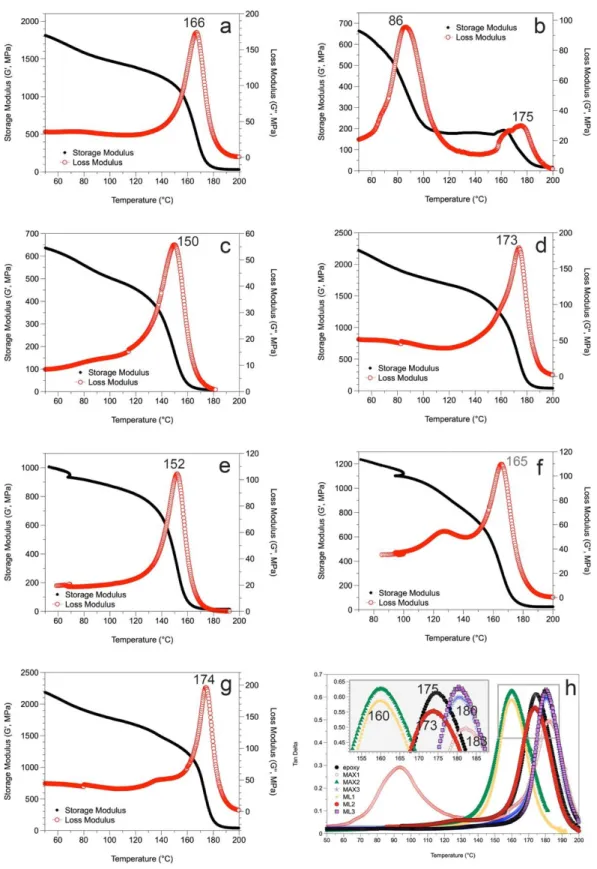
In this study, low-temperature G’ (i.e. 50 °C; G’50) of composites was compared with neat epoxy. The G’50 of epoxy was 1800 MPa. G’50 of MAX1-3 composites were 655, 648 and 2200 MPa, respectively (Figure 3a-d). Only when 4 wt. % Ti3AlC2 particles were incorporated, the G’; the capacity of the composite to support mechanical loads with recoverable viscoelastic deformation, increased. This increase in G’ from 1800 to 2200 MPa with 4 wt. % Ti3AlC2 incorporation was probably due to the interfacial interactions between octahedral layer surfaces of Ti3AlC2 and epoxy chains, which inturn restricted the movement of the local epoxy chains around the layers. The negative effect of Ti3AlC2 incorporation (MAX1,2) at low ratios was due to the agglomeration of Ti3AlC2 particles in some regions of the matrix. The difference in the regional movement in the matrix, the phase separation, was evident from the two peaks occurred in the G’’ (Figure 3b, at 86 and 175 °C). The agglomerated volume of particles inhibited complete wetting of particles by the epoxy monomer. In these regions, presence of MAX particles were dominant; epoxy chains could not crosslink and were highly mobile, thereby the G’ decreased (G’’ increased) remarkably. This result was also supported by the XRD patterns of MAX1 and 2, in which diffraction from the distorted Ti3AlC2 surfaces (00l) was dominant over amorphous epoxy hump. As Ti3AlC2 content was increased further (MAX2), this phase separation started to disappear and at 4 wt. % incorporaton (MAX3), the structure became highly crosslinked.
G’50 value of MXene composites (ML1-3) were 1000, 1205, 2200 MPa, respectively. Similar to MAX composites, only when 4 wt. % mL-Ti3C2 was reinforced, the G’ value increased remarkably compared to neat epoxy. The value of G’ at 4 wt. % of MAX and MXene incorporation was equivalent (2200 MPa), pointing out that unmodified Ti3C2 surfaces in MAX was equivalently reactive upon epoxy interaction to the (-O, -OH, -F) terminated Ti3C2 surfaces, which is formed after etching.
As mentioned before, Tg is a direct indication of the degree of crosslinking in a polymer. It is reliable to measure Tg from tan (Souza et al. 2014). It has been stated that rigid fillers increase the G’ of the polymer and shift Tg to higher temperatures by restricting the movement of the chains (Kaya, Tanoğlu, and Okur 2008; Kausar, Anwar, and Muhammad 2016; Choi 2013; Rao et al. 2009). As the polymer chain movement is restricted, the polymer would be more stable against fracture. Thereby, incorporation of rigid MAX and MXene fillers increased the G’ of the polymer and shifted Tg to higher temperatures by restricting the movement of the epoxy chains. By incorporating 0.4, 2 and 4 wt. % Ti3AlC2 to epoxy, Tg decreased from 175 °C to 90 °C then increased to 160 °C and 180 °C, respectively. By incorporating 0.4, 2 and 4 wt. % mL-Ti3C2 to epoxy, Tg decreased from 175 °C to 160 °C then increased to 173 °C and 180 °C, respectively. Segmental movement of the epoxy chains were restricted in filler accumulated regions, causing the formation of two distinct peaks in the G’’. However, mL-MXenes were distributed more homogeneously in the structure, which is why a second Tg peak was not observed in ML1 composite compared to the identical incorporation of Ti3AlC2 (MAX1).
Figure 3. a-g) Storage modulus (G’) and Loss modulus (G’’) variation of a) neat epoxy, b) MAX1, c) MAX2, d) MAX3, e) ML1, f) ML2 and g) ML3 composites and h) Tan delta () variation in Ti3AlC2
(MAX-1/3) and mL-Ti3C2 (ML-1/3) -epoxy composites as a function of temperature.
In summary, epoxy was reinforced with mL-Ti3C2 (MXene) at 0.4, 2, and 4 wt. % and the cured composite structure was compared to epoxy reinforced with Ti3AlC2 (MAX) at identical ratios. In MAX
structure, the interplanar spacing between the octahedral Ti3C2 layers were filled with Al, so that the epoxy could not wet between the layers. But in MXene composites, the layers were exfoliated during processing leading to good dispersion inside the monomer and could be filled with epoxy providing a homogeneous microstructure, which was deducted from the absence of segmental differences in epoxy chain movement during heating of MXene composites. XRD analysis showed that the MXene layers were delaminated during processing, possibly due to harsh high-shear mixing conditions. Tg of epoxy shifted from 175 to 180 and 183 C by 4 wt. % incorporation of MAX and mL-MXene. To get these enhanced structural properties, neither MAX, nor MXene particles were chemically treated, showing the potential of MXene composites to serve as alternative materials to currently used structural composites in the industry. Morphology and Microhardness of the Composite Surfaces
Until recently, the best candidate for reinforcing polymers have been recognized as the clays with nano layer thicknesses and graphene. However, it has been shown that the surfaces of both clay layers and graphene must be chemically modified before incorporation, since they stack face to face in the agglomerated tactoids making them incompatible with hydrophobic polymers (Zabihi et al. 2018). Results in this study showed that MAX and MXenes can be incorporated into epoxy and be well-dispersed without chemical treatment, probably owing to the interactions of Ti3C2 surfaces with epoxy chains. In Figure 4a-c, the representative SEM micrographs of the composites are shown.
Figure 4. SEM micrographs of a,b) MAX3, c) ML3 composites d) Vickers microhardness of MAX1-3 and ML1-3 composites
The SEM image of the bulk MAX3 composite in Figure 4a, reveals that the large, agglomerated chunks of Ti3AlC2 are well-dispersed inside the epoxy matrix. The size of the agglomerates were roughly larger than 10 µm. XRD analysis revealed that, when ground into particles, the X-rays were majorly diffracted from the epoxy at 4 wt. % incorporation. This means that the epoxy chains covered and strongly bound to the Ti3AlC2 particles as illustrated in Figure 2b. In Figure 4b, one of the agglomerates inside a crack is clearly observed. Despite the fact that large aggomerates are stress concentrators thereby critically harmful
for the mechanical properties upon crack propagation, they can act as crack deflection or bridging particles upon plastic deformation up to certain degree of reinforcement. In Figure 4d, this positive effect of MAX incorporation on surface hardness of epoxy is obvious. At low reinforcement (0.4 wt. %), the Vickers microhardness was not influenced remarkably. Two different Tg values obtained by DMA analysis indicated a phase separation inside this composite matrix. Since the ratio of MAX particles was low, the major portion of the hardness was influenced by the epoxy matrix. The microhardness of neat epoxy was 18.9 ± 1.85 HV. Because of the segmental differences in the composite structure, hardness decreased to 17.9 ± 1.68 HV at 0.4 wt. % Ti3AlC2 content. As the MAX content increased to 2 wt. %, the microhardness value increased (MAX1) to 20.85 ± 4.71 HV (MAX2). As the reinforcement was increased further to 4 wt. %, hardness did not increase further ; average hardness was identical with a lower standard deviation (20.65 ± 2.96 HV). A narrower deviation from the average is a sign of enhanced homogeneity in dispersion of the particles in the matrix, which was clear in Figure 4a.
In Figure 4c, the SEM image of the bulk ML3 composite is shown. The white areas are the cross sections of the Ti3C2 layers. As the figure shows it clearly, the mL-Ti3C2 layers were almost completely exfoliated (delaminated) upon composite processing, probably during high-shear mixing. Exfoliation was also indicated by the XRD analysis; from the disappearance of the (002) peak corresponding to the interplanar spacing between the (002) octahedral multilayers. The peak is expected to shift to lower degrees as the space between the layers is filled with epoxy. But, if the layers are completely seperated, the peak signal is completely lost like in ML3 composite in Figure 4c. As the Figure 4c shows, the composite microstructure was relatively homogeneous, the exfoliated layers were well-dispersed. This homogeneous structure influenced microhardness remarkably. The microhardness of epoxy first did not change (18.8 ± 1.70 HV) then incresed to 23.25 ± 4.65 HV and 27.45 ± 5.05 HV, by 0.4, 2 and 4 wt. % mL-Ti3C2 addition, respectively. The incorporation of Ti3C2 layers enhanced the resistance of the epoxy surface to mechanical loading. CONCLUSIONS
This study was performed to show the potential use of MXenes as epoxy reinforcer for structural applications that necessitate good mechanical properties without sacrificing from advantageous properties of epoxy. Results demonstrated that both MAX and MXene particles could be incorporated up to 4 wt. % and interlocked with epoxy chains at the interface without necessitating of the MAX/MXene chemical functionalization as such in clay/ and graphene/epoxy composites. The applied high-shear mixing caused in-situ delamination of mL-Ti3C2Tx layers and dispersion in the matrix without agglomeration. The enhancement in storage modulus and Tg was slightly more pronounced in MAX composites, however, incorporation of Ti3C2 layers into epoxy at identical ratios influenced hardness remarkably more than Ti3AlC2 particles. Storage modulus was the measure of elastic resistance of the material to mechanical loading. Tg was a measure to compare the crosslinking efficiency. These two properties were related to each other and both depend on the inhibition of polymer chain movement during heating/mechanical loading. So, even in agglomerated form, large MAX particles could act as particulate blocks against polymer chain movement owing to the increased crosslinking between the monomer and Ti3AlC2 particle surfaces. This increased the storage modulus of epoxy from 1800 to 2200 MPa by 4 wt. % reinforcement. A similar effect was observed in ML composites. The amount of increase in Tg was evident but lower in MXene incorporated composites compared to that of MAX incorporated. The microhardness increased 46 % only by 4 wt. % mL-Ti3C2 reinforcement. These improvements confirmed the potential use of two-dimensional layered carbides in overcoming the shortcomings of epoxy matrix in structural composites. Owing to the attractive features of the Ti3C2 layers, these composites carry potential to be used in a diverse area of applications including electromagnetic shielding, aerospace and marine applications.
ACKNOWLEDGEMENT
Author acknowledges Prof. Dr. Michel W. Barsoum and TUBITAK 2214 (International Research Fellowship) Program. Author also acknowledges Prof. Dr. Giuseppe Palmese for providing DMA analysis equipment.
REFERENCES
Anasori, Babak, Maria R Lukatskaya, and Yury Gogotsi. 2017. '2D metal carbides and nitrides (MXenes) for energy storage', Nature Reviews Materials, 2: 16098.
Atif, Rasheed, Islam Shyha, and Fawad Inam. 2016. 'Mechanical, thermal, and electrical properties of graphene-epoxy nanocomposites—A review', Polymers, 8: 281.
Barsoum, M. W., 2013, MAX Phases: Properties of Machinable Ternary Carbides and Nitrides, Wiley-VCH Verlag GmBH & Co., Weinheim, Germany.
Choi, Ilbeom. 2013. 'Surface modification of carbon fiber/epoxy composites with randomly oriented aramid fiber felt for adhesion strength enhancement', Composites Part A: Applied Science and Manufacturing, 48: 1-8.
Ehrenstein, Gottfried W, Gabriela Riedel, and Pia Trawiel. 2012. Thermal analysis of plastics: theory and practice (Carl Hanser Verlag GmbH Co KG).
Ghidiu, Michael, Maria R Lukatskaya, Meng-Qiang Zhao, Yury Gogotsi, and Michel W Barsoum. 2014. 'Conductive two-dimensional titanium carbide ‘clay’with high volumetric capacitance', Nature, 516: 78.
Jin, Fan-Long, Xiang Li, and Soo-Jin Park. 2015. 'Synthesis and application of epoxy resins: A review', Journal of Industrial and Engineering Chemistry, 29: 1-11.
Kausar, Ayesha, Zanib Anwar, and Bakhtiar Muhammad. 2016. 'Recent developments in epoxy/graphite, epoxy/graphene, and epoxy/graphene nanoplatelet composites: a comparative review', Polymer-Plastics Technology and Engineering, 55: 1192-210.
Kaya, Elcin, Metin Tanoğlu, and Salih Okur. 2008. 'Layered clay/epoxy nanocomposites: Thermomechanical, flame retardancy, and optical properties', Journal of applied polymer science, 109: 834-40.
Kumar, Abhishek, and Samit Roy. 2018. 'Characterization of mixed mode fracture properties of nanographene reinforced epoxy and Mode I delamination of its carbon fiber composite', Composites Part B: Engineering, 134: 98-105.
Laouchedi, Dalila, Boudjema Bezzazi, and Chouaib Aribi. 2017. 'Elaboration and characterization of composite material based on epoxy resin and clay fillers', Journal of applied research and technology, 15: 190-204.
Li, Yan, Han Zhang, Harshit Porwal, Zhaohui Huang, Emiliano Bilotti, and Ton Peijs. 2017. 'Mechanical, electrical and thermal properties of in-situ exfoliated graphene/epoxy nanocomposites', Composites Part A: Applied Science and Manufacturing, 95: 229-36.
Liu, Shan, Venkata S Chevali, Zhiguang Xu, David Hui, and Hao Wang. 2018. 'A review of extending performance of epoxy resins using carbon nanomaterials', Composites Part B: Engineering, 136: 197-214.
Ma, Peng-Cheng, Shan-Yin Mo, Ben-Zhong Tang, and Jang-Kyo Kim. 2010. 'Dispersion, interfacial interaction and re-agglomeration of functionalized carbon nanotubes in epoxy composites', Carbon, 48: 1824-34.
May, Clayton. 1987. Epoxy resins: chemistry and technology (CRC press).
Naguib, Michael, Murat Kurtoglu, Volker Presser, Jun Lu, Junjie Niu, Min Heon, Lars Hultman, Yury Gogotsi, and Michel W. Barsoum. 2011. 'Two-Dimensional Nanocrystals Produced by Exfoliation of Ti3AlC2', Advanced Materials, 23: 4248-53.
Poonpipat, Yanika, Kritsanachai Leelachai, Raymond A Pearson, and Peerapan Dittanet. 2017. 'Fracture behavior of silica nanoparticles reinforced rubber/epoxy composite', Journal of Reinforced Plastics and Composites, 36: 1156-67.
Prolongo, SG, BG Meliton, G Del Rosario, and A Ureña. 2013. 'New alignment procedure of magnetite– CNT hybrid nanofillers on epoxy bulk resin with permanent magnets', Composites Part B: Engineering, 46: 166-72.
Radovic, Ljubisa R, Alejandro Suarez, Fernando Vallejos-Burgos, and Jorge O Sofo. 2011. 'Oxygen migration on the graphene surface. 2. Thermochemistry of basal-plane diffusion (hopping)', Carbon, 49: 4226-38.
Rao, C. N. R., A. K. Sood, K. S. Subrahmanyam, and A. Govindaraj. 2009. 'Graphene: The New Two-Dimensional Nanomaterial', Angewandte Chemie International Edition, 48: 7752-77.
Souza, Virgínia S, Otávio Bianchi, Martha FS Lima, and Raquel Santos Mauler. 2014. 'Morphological, thermomechanical and thermal behavior of epoxy/MMT nanocomposites', Journal of Non-Crystalline Solids, 400: 58-66.
Sowichai, Kanokwan, Sitthisuntorn Supothina, On-uma Nimittrakoolchai, Takafumi Seto, Yoshio Otani, and Tawatchai Charinpanitkul. 2012. 'Facile method to prepare magnetic multi-walled carbon nanotubes by in situ co-precipitation route', Journal of Industrial and Engineering Chemistry, 18: 1568-71.
Srivastava, Shakun, and Anjaney Pandey. 2019. 'Mechanical behavior and thermal stability of ultrasonically synthesized halloysite-epoxy composite', Composites Communications, 11: 39-44. Wang, Fuzhong, Lawrence T Drzal, Yan Qin, and Zhixiong Huang. 2016. 'Enhancement of fracture
toughness, mechanical and thermal properties of rubber/epoxy composites by incorporation of graphene nanoplatelets', Composites Part A: Applied Science and Manufacturing, 87: 10-22.
Wang, Xiao, Jie Jin, and Mo Song. 2013. 'An investigation of the mechanism of graphene toughening epoxy', Carbon, 65: 324-33.
Xu, Peng, James Loomis, Ben King, and Balaji Panchapakesan. 2012. 'Synergy among binary (MWNT, SLG) nano-carbons in polymer nano-composites: a Raman study', Nanotechnology, 23: 315706.
Yousri, Omar M, Mohamed Hazem Abdellatif, and Ghada Bassioni. 2018. 'Effect of Al $$ _ {2}\mathrm {O} _ {3} $$ Nanoparticles on the Mechanical and Physical Properties of Epoxy Composite', Arabian Journal for Science and Engineering, 43: 1511-17.
Zabihi, Omid, Mojtaba Ahmadi, Saeid Nikafshar, Karthik Chandrakumar Preyeswary, and Minoo Naebe. 2018. 'A technical review on epoxy-clay nanocomposites: Structure, properties, and their applications in fiber reinforced composites', Composites Part B: Engineering, 135: 1-24.
Zaman, Izzuddin, Fethma M Nor, Bukhari Manshoor, Amir Khalid, and Sherif Araby. 2015. 'Influence of interface on Epoxy/clay nanocomposites: 1. Morphology structure', Procedia Manufacturing, 2: 17-22.