SAKARYA ÜNİVERSİTESİ FEN BİLİMLERİ ENSTİTÜSÜ DERGİSİ
SAKARYA UNIVERSITY JOURNAL OF SCIENCE
e-ISSN: 2147-835X
Dergi sayfası: http://dergipark.gov.tr/saufenbilder
Geliş/Received 05.02.2017 Kabul/Accepted 26.04.2017 Doi 10.16984/saufenbilder.289938
*Sorumlu Yazar/Corresponding Author: Arif Ankarali
*1Faculty of Engineering and NaturalSciences, Ankara Yildirim Beyazıt University, Ankara, Türkiye 2 School of Engineering and NaturalSciences, İstanbul Medipol University, İstanbul, Türkiye 3Faculty of Engineering, King Abdulaziz University, Jeddah, Saudi Arabia
This paper is the reorganized version of the paper presented at ISITES 2017 conference. This study is supported by College of Engineering of the USF and partly supported by BAP Office of Ankara Yıldırım Beyazıt University.
Zaman gecikmeleriyle birlikte bozucu etkilere maruz kalan bir dc servomotorun
geribeslemeli kontrolü
*1Arif Ankaralı, 2Hüseyin Arslan and 3Hamza Diken
ÖZ
Kablosuz kontrol sistemlerinde, kontrol sinyallerin iletiminde oluşan zaman gecikmeleri sistemin kararlı bir cevap üretmesini zorlaştırır. Özellikle ileri hatta ve geribesleme hattında oluşan toplam gecikmelerin etkisi nedeniyle, kontrol edilen sistemde kararlılık problemleri oluşur. İnsansız hava araçlarında, uzay manipülatörlerinde ve insansı robotlar gibi elektromekanik sistemlerde bulunan servomotorların, uzaktan gönderilen kontrol sinyalleriyle gerçek zamanlı kontrolünde, gecikme zamanlarının etkisi oldukça önemlidir. İleri hatta bilgisayar yazılımlarının koşturulma süreleri, verilerin ara birimlerde depolanma süreleri, antenler üzerinden kablosuz gönderilme-alınma süreleri ve ilave donanımlar üzerinden geçerken oluşan gecikmeler kontrol sinyallerinin toplam gecikme zamanını oluşturmaktadır. Benzer şekilde geri besleme hattında da ölçülen konum/hız geribesleme sinyallerinin, ters yönde donanımlar üzerinden benzer işlemlerle geçerken oluşan toplam gecikmeler sözkonusudur. Bu makalede, PID ile kontrol edilen bir DC motorun her iki yönde de oluşan sabit zaman gecikmeleri için davranışı detaylı bir şekilde incelenecektir. Zaman gecikmelerinin sistem davranışı üzerindeki etkilerini inceledikten sonra, modele Smith kestiricisi ilave edilerek servomotorun cevabında oluşacak ve istenmeyen davranışların minimize edilmesi sağlanacaktır. İlave olarak, kontrol edilen sistemdeki bozucu etkilerin kestirilerek düzeltilmesi için yeni bir Smith algoritması modele ilave edilmiştir. Bozucu etkinin hesaba katıldığı ve katılmadığı durumlar için geliştirilen Smith kestiricilerin ayrı ayrı başarıları, PID kazanç değerleri optimize edilmiş bir kontrolcüyle sürülen düşük güçlü bir servomotor üzerinde benzetimlerle gösterilmiştir.
Anahtar Kelimeler: kablosuz kontrol, yenilenmiş Smith kestirimcisi, servomotor, zaman gecikmesi, PID kontrol
Feedback control of a dc servomotor with time delays subjected to disturbance
signals
ABSTRACT
The time delay imposed in the wireless control systems makes it difficult to guarantee stable response in many cases. Especially, delays in feedforward path combined with feedback path may result in some stability problems of the controlled system response. For the remote control of servomotors used on unmanned aerial or underwater vehicles, space manipulators and humanoid robots time
feedforward path may be caused by computer control algorithm processing, buffering, transmitting process of control signals through antenna, receiving process of control signals through antenna on the vehicle and the complementary hardware processing. Similarly, on the feedback path, position feedback signal measured by encoder is transmitted in reverse order of the control signal with some delay time. In this paper, the PID control of a DC servomotor with constant time delays will be discussed in detail. After specifying the effects of the delays in the system, Smith predictor will be added to the model to minimize the undesired effects on the output response of the servomotor. For the wireless control of the servomotors actuating some mechanical systems, a modified Smith predictor is designed to drive the system efficiently to take care of the disturbance effects coming from the dynamics of the driven parts. The success of the calculated predictors together with the tuned PID controller and the controllable range for disturbance to controller signal ratio are shown on a low power DC servomotor by simulations.
Key words: wireless control, Modified Smith predictor, servomotor, delay, PID control.
1. INTRODUCTION
The wireless control of actuators with time delays in feedforward and feedback paths has great importance because of the closed loop instability caused by these delays. Time delays result in linear phase shifts that limit the control bandwidth and affect closed-loop instability. With the
technological developments on wireless
communication and the increasing need to remotely controlled mechatronic systems, more researches on this topic will be realized in addition to the studies that have been already done. Remote control of different systems like mobile robots, unmanned aerial vehicles (UAVs), chemical or nuclear processes require the time delay effects to be taken into consideration. Song et al. studied on network based time delay and they proposed a new distributed control scheme that can compensate for the effects of the time delay. Their study is based on the PID controller with the Smith predictor and disturbance observer. Theoretical analysis are implemented with tracking position control experiment of a geared DC Servo motor and the performance is improved by augmenting a PID controller with both the Smith predictor and disturbance observer under the time delay in the network [1]. The controller design for a class of systems with actuator failures as well as time delays in control inputs is studied by Zhao et al. They applied Lyapunov stability criteria to guarantee the robust stability and certain performance of the delayed system for both normal operation and actuator failure cases [2]. Luck and Ray had developed a predictor-controller algorithm to minimize the effects of the delays and the performance of the compensator tested on a
DC motor velocity control [5]. An early study to overcome the time delay issue is done by Furukawa and Shimemura. They proposed a predictive control to stabilize an unstable system
with time delays. They also showed
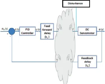
mathematically that a Smith predictor is unable to effectively control the unstable system [6]. Anguleova and Wennberg studied on the identifiability of the delay parameter with a single time delay. They gave the theorems and the proofs of identifiability for nonlinear systems for one time delay and applied on several examples [7]. The effects of the time delays in wired and wireless networks studied by many researchers. One of the recent surveys focused on Networked Control Systems (NSCs) is realized by Hepanha et al. [12]. In the wireless controlled systems described in Fig. 1, there are two parameters subjected to delays. One of them is the controller signal delay in feedforward path from controller to the actuator and the other is feedback signal delay from sensor to the controller. Those delays are mainly caused by the processing delays of control algorithms, buffering delays of the generated information, device delays of electronic components, transmitting-receiving delays and transportation delays of the signal on the way. Similarly, the delays in control of wireless sensor-actuator systems, the total delay is the sum of processing delay, buffering delay, in feedforward path and sensor measuring delay, transmitting-receiving delays in feedback path. The importance of the delays of the sensor-actuator systems is that it directly effects the dynamic behavior of the actuator and can even make the actuator unstable. The main purpose of this study is to understand the basics of a remotely controlled DC servomotor under the effect of delays and the disturbances
A. Ankaralı, H. Arslan, H. Diken Feedback Control of a DC Servomotor with Time Delays Subjected to Disturbance Signals coming from the dynamics of the actuated
mechanical system. Since the torque disturbance on the servomotor shaft can be calculated through equations of motions of the driven system, it’s quite possible to introduce these varying torque values to the Smith predictor and produce a control signal which takes care of those disturbing effects. For the future modelling and simulation of servomotor actuated robotic systems, as a first step, the overall closed loop transfer functions of the system on hand will be obtained and tested if they works accurate. This paper is organized as follows: First of all, closed loop transfer function of a PID controlled servomotor with feedforward
and feedback constant delays including
disturbance is obtained. This system is given in Fig. 1. Then, a modified Smith predictor is included in the model to overcome delays and disturbance effects together. In simulations section, all of the derived transfer functions are utilized to show the designed PID controller-Smith predictor collaboration success by means of step input response of the servomotor.
2. MODIFIED SMITH COMPENSATOR DESIGN FOR DISTURBANCES Fig. 1 shows the closed loop system on hand with a disturbance input. When the mechanical systems driven by servomotors are considered, the inertia effects of the loads may be included to the system as a disturbance [13] and a study is realized by Ankarali previously [14].
Figure 1. The wireless PID controlled servomotor and sensor system.
a link rotated by the servomotor will cause a torque and this torque will be calculated through dynamic
equations and introduced to the controlled system to compensate the effect of the inertia. The mathematical model of P can be found in [15]. In this case, the compensator obtained in [16] will be modified to overcome the effect of this type of external loading applied on the motor shaft. Ankarali and Arslan studied on the effects of time delays in feed forward and feedback paths for wireless control of the DC servomotor. A Smith Predictor is successfully obtained and applied to the servomotor to compensate the delay effects [16]. In this case, the closed loop transfer function of the system is again obtained by assuming that the system is time-invariant and linear. From the block diagram in Fig.2, modified Smith predictor can be formulated as:
( ) =
( )[ ( ) ](1)
P(s) is the transfer function of the plant and
obtained as [15, 16],
( ) = ( )
( ) = +
Where
= , = + ( / ), =
Dc and Df are the delays in feedforward and
feedback paths and defined as, ( ) = ( ) =
The term λ represents the ratio of disturbance signal to controller signal and defined as:
( ) = ( )
( ).
After replacing the related terms into Eqn.(1)
given above, and making necessary
simplifications, modified Smith predictor is obtained as
( ) =
∅ (2) Where = , = + − , = − , = , ∅ = + , = .loop response of the system can be obtained by adding the reference input response and the disturbance response of the system [14]. The closed loop transfer function of the system for reference input may be obtained by letting the external disturbance input is zero. So, the closed loop transfer function for reference input can be obtained as: = ( ) ( ) = ( ) ( ) 1 + ( ) ( ) + ( ) ( )
=
∅ (3) Where ∅ = , = + + , = + + , = (1 + ) = , ̃ = ( + 2 + ), = + + + + 2 , = + + + , ̃ = + , = .Similarly, the closed loop transfer function for disturbance input can be obtained as:
( ) = ( ) ( ) = [1 + ( ) ( )] ( ) 1 + ( ) ( ) + ( ) ( )
=
∅ (4) Where = , = + + + , ∅ = + + + + + − , = + + − + − , = + − − , = − ( ), = + , ̃ = ( + ) + + + , = ( + ) + + + + ( + + − ), = ( + ) + + − + + + + + − , ̃ = ( + ) + − + + + − − ( − 1), = + − − ( + )( − 1), = − ( − 1).The overall closed loop transfer function of the system with external disturbance input is the sum of reference input response and disturbance input response
( ) = ( ) + ( ) (5)
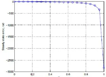
For simulation purposes, the value of λ in Eqn. (1) should be kept within a limited range for the system to run in stable region. In this case, selection of the reference input signal as a step input together with a retuned PID controller gains for the possible λ range will be reasonable. The effect of the λ variations on steady state because of the disturbance input with constant feedforward and feedback delays are shown in Figure 5.
3. SIMULATIONS
Several Matlab scrips are written to make the desired simulations. Simulink models of the systems are designed in parallel to double check if the codes are giving reliable results. The derived closed loop transfer functions utilized in scripts give almost the same result as the Simulink diagrams in which all of the individual blocks are joined to each other as given in Fig.2. The values of characteristic parameters of the selected servomotor are given in Table 1 [8]. This is a small sized and low power DC motor suitable for low torque required applications with high sensitivity. The remote control system block diagram is given in Fig.2. Dc and Df blocks represents controller
signal delay and sensor feedback delay regarding respectively during the wireless communication between controller and the servomotor with an encoder. PID gains of the controller for desired performance of the motor are obtained by tuning the linear model and given in Table 2. These gains
A. Ankaralı, H. Arslan, H. Diken Feedback Control of a DC Servomotor with Time Delays Subjected to Disturbance Signals correspond to zero time delays in the system. The
3-D surface plot of the response of the system with respect to time delays and simulation time between 0-60 ms can be seen in Fig. 3.
Table 1. Characteristics of the servomotor used in simulations
Explanation Symbol Value Inertia of the rotor (g cm2) j
0 11
Inductance (mH) La 0.108
Resistance (Ohm) Ra 1.46
Torque constant (mNm/A) K2 19
Mechanical time constant (ms) Tm 4.43
Table 2. Optimized gains of the PID controller used in simulations
Explanation Symbol Value
Proportionality gain Kp 7.69
Integral gain Ki 39.35
Derivative gain Kd 0.00
It’s clear that increase in time delays introduced to the system with tuned PID gains dramatically affects the step response of the servomotor. The delay time range is defined by considering the maximum allowable wireless communication delays like ZigBee, Wi-fi and Bluetooth. The simulation results belonging to Modified Smith predictor-PID controlled servomotor as given in
Figure 3. PID controlled DC servomotor response for delays between 0-60 ms.
Figure 4. Modified Smith Predictor-PID controlled servomotor response with disturbance input for different wireless communication delays (λ=0.01, Kp=7.6983, Ki=39.3528, Kd=0).
Figure 5. The effect of disturbance on steady state error of the servomotor with PID- Modified Smith controller (Kp=7.6983, Ki=39.3528, Kd=0)
Fig. 4 are plotted on the same graph for varying delay times between 0-60 ms. For the same range of delays, the Matlab script written for the system given in Fig. 1, which is including an external disturbance, is run and results are seen on Fig. 3. In these simulations, simulation time is selected as 1.4 second which corresponds to settling time of the servomotor. By keeping the simulation time small enough, the difference between each delay dependent response tried to make observable on the same graph. The effect of the λ on steady-state error is given in Fig. 5. Simulation time is taken as the same with previous simulation, which provides required information about the whole system’s sensitivity to this parameter’s variation.
4. CONCLUDING REMARKS
This study is planned as the first step towards wireless control of mobile robotic systems where main control unit is far away from the electromechanical system itself. Because, most of those systems use servomotors for actuation and sensors for feedback information about position, velocity and/or torque. So, understanding the response behavior of these systems subjected to delays together with external disturbances is quite important.
To prevent the servomotor from instability because of delays and external disturbance, Modified Smith predictor is designed. The performance of the Modified Smith predictor with PID controller is examined by means of simulations on a specific servomotor. In this model, in addition to delays, an external disturbance is added to the system and the Modified Smith predictor is calculated for this case and the success is tested on the servomotor. In this perspective, the response of a low power, small sized high frequency servomotor is studied by simulations under the effect of delays and external disturbances in detail. The basic technical specifications of the studied servomotor are given in Table 1. The tuned gains of the PID controller without delay case are given Table 2. All of the evaluations for the cases studied above are done due to these gain values. The servomotor is assumed to be used on a mobile robot and controlled from a fixed controller unit in a wireless fashion. So, the delay range related with wireless
communication methods are taken into
consideration and the effect of those are examined on the control of the selected servomotor.
First of all, the closed loop transfer function of the servomotor control system for constant delays in feedforward and feedback paths is obtained. The step response of the system between 0-60 ms delays without compensator are simulated and given in Fig.3. It’s clear that time delays in the system directly affects the dynamic behavior of the motor and results in changes in rise time, peak time, max. peak and settling time as seen in Fig. 3. As the delay time is increased the system response to step input becomes more oscillatory and tends to go to instability. To keep the DC servomotor response in the stable region and eliminate the delay effects, a Modified Smith predictor is
introduced to the system as given in Fig. 2. By reduction of this block diagram and replacing the transfer functions of individual components together with block, the overall transfer function of the Modified Smith predictor PID controlled servomotor with delays is obtained and given as Eq. (5).
The simulations using the given block diagram and the related closed loop transfer functions for a step input shows that the designed modified compensator is perfect and the response is almost the same although the applied time delays are varying as given in Fig.3 if the disturbance is zero. It’s observed that the Modified Smith predictor works well and does not allow the maximum peaks to jump some undesired values.
However, the effect of the delay is observed as a time shift in step response behavior of the servomotor and this shift is directly proportional to the delay time. The rise time and the peak time are also shifting slightly towards right with increasing delays as expected. The settling time is about 1.4 seconds and almost the same for each simulation. For external disturbance compensation, a modified Smith predictor is designed as given in Eq. (2). For this case, again, the closed loop transfer function of the whole system is obtained and used for simulations. Fig. 4 declares that the predictor works well and similar response characteristics of the first case given in [15] is observed for the value of λ parameter as zero.
The eligibility region of λ remains to be determined. Because for small values of λ ≤ 0.4 steady state errors are nearly zero but for higher values they increase to unallowable values as seen on Fig. 4. Additionally, as λ increases, maximum peaks of step responses also increase as given in Fig. 5. So, it can be concluded that up to some certain values of λ system work fine depending on the expected requirement criteria of the system. But after that value, for keeping the peaks in a certain limited range the system may need some adaptive nature. So that PID gains may be tuned due to the changing dynamics of the system which result in λ increase to get the satisfactory response from the system.
A. Ankaralı, H. Arslan, H. Diken Feedback Control of a DC Servomotor with Time Delays Subjected to Disturbance Signals REFERENCES
[1] Ki-Won Song, Gi-Sang Choi, and Gi-Heung Choi, Tracking Position Control of DC Servo Motor in LonWorks/IP Network , International Journal of Control, Automation, and Systems, vol. 6, no. 2, pp. 186- 193, 2008.
[2] Qing Zhao and Chuwang Cheng, State Feedback Control for Time Delayed Systems with Actuator Failures, Proceedings 01 the American Control Conference, Denver, Colorado June 4-6, 2003.
[3] Qing-Chang Zhong, Robust Control of Time-delay Systems, Springer Verlag London Limited 2006
[4] Katsuhiko Ogata, Modern Control
Engineering, Prentice Hall, 2010
[5] Rogelio Luck and Asok Ray, Experimental verification of a delay compensation algorithm for integrated communication and control systems,Int. J. Control, Vol. 59, No.6, 1357-1372, 1994 [6] Toshio Furukawa and Etsujiro Shimemura, Predictive control for systems with time delay, Prentice Hall, 2010
[7] Milena Anguelova and Bernt Wennberg, State elimination and identifiability of the delay parameter for nonlinear time-delay systems, Automatica 44, 1373-1378, 2008
[8]http://www.maxonmotorusa.com/maxon/ view/
catalog/
[9] Han-Qin Zhou, Qing-Guo Wang and Liu Min, Modified Smith predictor design for periodic disturbance rejection, ISA Transactions, V. 46, 493- 503, 2007
[10] Chien-Liang Lai and Pau-Lo Hsu, Design the Remote Control System With the Time-Delay Estimator and the Adaptive Smith Predictor, IEEE Transactions on Industrial Informatics, Vol. 6, No. 1, 2010
[11] A. Terry Bahill, A Simple Adaptive Smith-Predictor for Controlling Time-Delay Systems, Control systems magazine, 16-22, 1983
[12] Joao P. Hespanha, Payam Naghshtabrizi, and Yonggang Xu,A Survey of Recent Results in Networked Control Systems, Proceedings of the IEEE, Vol. 95, No. 1, January 2007
[13] K.S. Fu, R.C. Gonzales and C.S.G. Lee, Robotics: Control, Sensing and Vision, McGraw Hill Book Company, 1987
[14] Arif Ankarali, Fuzzy Logic Velocity Control of a Biped Robot Locomotion and Simulation, Int J Adv Robotic Sys., 2012, Vol. 9, 1-10,2012
[15] Katsuhiko Ogata, System Dynamics and Control, Prentice Hall, 2010
[16] Arif Ankarali and Hüseyin Arslan, "Smith Predictor Application on Wireless Dc Servomotor Control", 16. Mational Machine Theory Symposium, Atatürk University, Engineering Faculty, 12-13 June, 2013, Erzurum, TURKEY