Nonuniform friction-area dependency for antimony oxide surfaces sliding on graphite
Claudia Ritter,1,2Mehmet Z. Baykara,3Bert Stegemann,4Markus Heyde,1,*Klaus Rademann,1Jan Schroers,2and Udo D. Schwarz2,†
1Institute of Chemistry, Humboldt Universit¨at zu Berlin, Brook-Taylor-Strasse 2, 12489 Berlin, Germany
2Department of Mechanical Engineering and Materials Science and Center for Research on Interface Structures and Phenomena (CRISP),
Yale University, P.O. Box 208284, New Haven, Connecticut 06520, USA
3Department of Mechanical Engineering and UNAM–Institute of Materials Science and Nanotechnology, Bilkent University,
Bilkent, 06800 Ankara, Turkey
4Hochschule f¨ur Technik und Wirtschaft Berlin–University of Applied Sciences, Wilhelminenhofstrasse 75A, 12459 Berlin, Germany (Received 15 March 2013; revised manuscript received 14 June 2013; published 15 July 2013)
We present frictional measurements involving controlled lateral manipulation of antimony nanoparticles on graphite featuring atomically smooth particle-substrate interfaces via tapping- and contact-mode atomic force microscopy. As expected from earlier studies, the power required for lateral manipulation as well as the frictional forces recorded during the manipulation events exhibit a linear dependence on the contact area over a wide size range from 2000 nm2to 120 000 nm2. However, we observe a significant and abrupt increase in frictional force and dissipated power per contact area at a value of about 20 000 nm2, coinciding with a phase transition from amorphous to crystalline within the antimony particles. Our results suggest that variations in the structural arrangement and stoichiometry of antimony oxide at the interface between the particles and the substrate may be responsible for the observed effect.
DOI:10.1103/PhysRevB.88.045422 PACS number(s): 68.35.Af, 68.35.Ct
I. INTRODUCTION
The ability to precisely predict and control macroscopic frictional phenomena requires an accurate understanding of the fundamental principles governing friction at the nanoscale. For the last two decades, related experimental investigations1,2 have largely relied on the friction force microscope (FFM) as an experimental tool.3Based on the basic operating principle of atomic force microscopy (AFM),4 the FFM allows the recording of lateral forces during the sliding of a sharp tip on a given sample surface, thereby providing important information about the frictional properties of nanoscale single-asperity contacts. To date, FFM has been extensively used to study a large variety of different material classes, including layered solid lubricants (e.g., graphite, molybdenum disulfide),5,6ionic crystals (KBr, NaCl),7,8ferroelectric materials (triglycine sul-fate, guanidinium aluminum sulfate hexahydrate),9,10 metals (copper, gold),11 and a number of novel “designer mate-rials” (graphene, hexagonal boron nitride);12,13 applications also comprised measuring friction as a function of various parameters (e.g., tip radius and shape, applied load, sliding velocity, and temperature).5,14–19
Despite the considerable success of the FFM method in observing fundamentally important effects such as stick-slip,20–23fricitonal anisotropy,9,24and structural lubricity,25it inherently involves a number of significant limitations:26
(1) The contact area between the FFM tip and the sample surface during the experiments is usually limited to a few nanometers squared and cannot be changed siginificantly through the variation of applied load. This severely degrades the ability to study frictional force as a function of contact area for a sufficiently wide range of contacts, limiting the extent of conclusions that can be drawn from FFM experiments.
(2) Commercial AFM cantilever tips used as probes in FFM experiments are made out of a very small number of materials (e.g., silicon, silicon dioxide/nitride, diamond), while sample
materials can be freely chosen. This limits the number of material combinations that can be investigated through FFM experiments.
(3) As the precise characterization of the atomic structure of tip apices is very difficult and their configurations may change during experiments, obtained FFM results cannot be correlated to specific interface structures, since it is a priori unknown whether the surface area of the tip that is actually in intimate contact with the sample during sliding is amorphous/disordered (which is generally the case) or features a certain level of crystallinity.
To overcome a majority of these limitations, Ritter et al. and Dietzel et al. have pioneered a new approach in which the AFM tip is used to laterally manipulate antimony (Sb) nanopar-ticles, which have been thermally deposited on graphite and MoS2, forming atomically smooth interfaces with their
substrates.27–31 Thus, experimentally observed contact areas represent the real contact areas between the nanoparticles and the substrate, eliminating the need to distinguish between the apparent and real contact area, as it is usually the case for typical interfaces involving multiple asperities.26With the exception of the occasional observation of virtually vanishing friction due to structural lubricity under unusually clean conditions (almost exclusively ultrahigh vacuum), recording the lateral forces experienced by the AFM tip during the manipulation events has revealed a linear dependence of frictional force (Ff) on nanoparticle-substrate contact area (A) for the investigated size regimes (usually between 10 000 nm2
to >100 000 nm2).29,30 In addition, the power required to laterally translate the nanoparticles (Ptip) has also been found
to depend linearly on A through the application of the so-called tapping/dynamic mode of AFM.27
In this paper, we report nanomanipulation experiments that include particles with contact areas as small as 2000 nm2. The
motivation for this range extension towards smaller particles is twofold:
(1) While previous experiments have revealed a strongly linear dependence of Ptip on A for contact areas of about
10 000 nm2and more, the extrapolation of the linear trend into
smaller contact sizes results in a negative Ptipvalue;27further
clarification of the specifics of the friction-area dependency for contact areas smaller than 10 000 nm2is therefore necessary
for a full characterization of the frictional behavior.
(2) It has been reported that Sb nanoparticles undergo a phase transition from amorphous to crystalline as their size increases.32 The phase transition, which is accompanied by a change of particle morphology from round and compact to branched, has been confirmed through transmission electron microscopy (TEM) measurements: While particles with con-tact areas above 25 000 nm2 have been found to be almost
exclusively crystalline, particles with contact areas below 15 000 nm2 are amorphous and spherical.32 Based on the very small number of investigated particles with contact areas smaller than 15 000 nm2 in previous studies, it is expected that experiments aimed at this size regime would provide new insights regarding the effect of particle structure on friction in nanomanipulation experiments.
II. EXPERIMENTAL
For the experiments, sample systems consisting of Sb nanoparticles thermally evaporated on graphite have been prepared. The antimony was vapor deposited onto a freshly cleaved graphite (0001) surface in ultrahigh vacuum chambers with base pressures of less than 6× 10⁻¹⁰ mbar. Deposition parameters were chosen such that particles with a large variety of contact areas were formed on the sample surface, while maintaining conditions that were designed to reproduce the earlier described structural amorphous-crystalline transition at around 15 000–25 000 nm2particle size. The AFM imaging
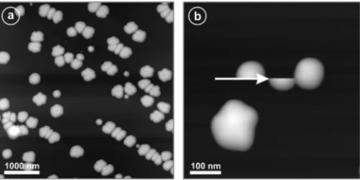
and nanomanipulation experiments as a function of A were performed under ambient conditions. A typical AFM image of the sample surface and an individual translation event are illustrated in Fig.1.
FIG. 1. (a) AFM image of a typical sample system consisting of antimony nanoparticles on a graphite substrate. The preparation conditions were chosen to produce particles of different sizes. The image demonstrates that smaller islands are round shaped, while larger ones are branched. (b) AFM image illustrating a typical nanomanipulation event in contact mode. The particle on the top left appears cut, as it is moved to the right by the AFM tip within the scan line indicated by the white arrow. The antimony particle on the top right prevents the translated particle from moving further to the right.
Great care has been taken to ensure reproducibility of the obtained data. Samples were produced in two different ultrahigh vacuum systems and analyzed using a home-built AFM33,34in dynamic mode, as well as a commercially avail-able AFM (Nanoscope Multimode AFM with Nanoscope III electronics by Bruker Corporation) operating in contact mode. The exact experimental procedures have been described in detail earlier;27,28,31 here, we will review them only briefly. In dynamic-mode manipulation of Sb nanoparticles, the cantilever attached to the tip is oscillated at its resonance frequency and taps the surface during imaging, transferring a certain amount of power to the sample. As the excitation amplitude is increased, while the tip is in the vicinity of an antimony particle, the amount of power transmitted to the particle by the tip increases, and when it passes a threshold value, the particle moves. The threshold power Ptip that is needed for nanomanipulation, which has been
found to depend linearly on frictional force through theoretical modeling,35 can be recorded for particles of different size, and a relation between Ptip and A may be formed. On the
other hand, contact-mode AFM has been used to laterally translate Sb nanoparticles by pushing them with the probe tip along a line passing through their center of mass. The recording of the lateral force experienced by the AFM tip during translation allows the direct study of the frictional resistance between specific nanoparticles and the substrate. Similar to the dynamic-mode manipulation, the applied load on the tip is incrementally increased until a translation event occurs. The lateral force value recorded during translation at this threshold load represents then the kinetic frictional force Ff for that specific particle.36It is important to point out that during all manipulation experiments, scanning directions and tip-particle contact points are chosen with respect to the center of mass of specific particles to avoid rotational motion during translation, in accordance with previous work.27,28Schematics describing the basic principles of the two approaches, as well as recorded topography, power dissipation, and frictional force values during actual nanomanipulation events are displayed in Fig.2.
III. RESULTS AND DISCUSSION
The dependence of Ptip and Ff on A during controlled nanomanipulation events is illustrated in Fig. 3 for contact areas ranging between 2000 nm2 to 110 000 nm2 [Fig.3(a)]
and 2000 nm2 to 58 000 nm2 [Fig. 3(b)]. While previous
studies conducted on nanoparticles with a minimum particle size of about 10 000 nm2 have revealed a unique linear
dependence between the respective quantities over the whole size range, such an overall linear relationship cannot be fitted for the whole data range covered in this study. Rather, two separate linear regimes can be defined for (i) clearly round and compact particles with contact areas of 16 000 nm2 and
below and (ii) clearly branched particles with contact areas of 25 000 nm2 and above. While there are several (presumably partially crystalline) particles around the transition region of 16 000 nm2 to 25 000 nm2 that do not clearly belong to
either linear regime, this does not affect the two linear trends observed sufficiently away from the transition region. For experiments conducted with dynamic-mode AFM [Fig.3(a)],
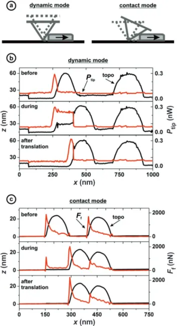
FIG. 2. (Color online) (a) Illustration of the two different ap-proaches for moving particles on the substrate surface used in this work. In the dynamic mode, the lateral force that eventually causes the particle to slide sidewards is created by the vertical movement of the tip’s sloped sides; the power dissipated during the particle’s translation is taken as characterizing the frictional loss (Ref.35). In contrast, the tip is used to push islands from the side in contact mode, resulting in a detectable twisting of the cantilever that is proportional to the frictional resistance of the particle. (b) Topography (z) and dissipated power (Ptip) signals recorded before, during, and after a translation event. As the topography line scan (black) indicates, the particle on the left moves≈130 nm to the right through a ≈0.25-nW increase in power dissipation (red). (c) Topography (z) and frictional force (Ff) signals recorded before, during, and after a translation
event. As the topography line scan (black) indicates, the particle on the left moves≈140 nm to the right, while a frictional force (Ff) of
about 300 nN is measured during the translation event (red).
we have found that Ptip= (0.006 ± 0.022) nW + A · (8± 2)/106 nW/nm2 for (i) and P
tip= (−0.5 ±
0.1) nW+ A · (25 ± 2)/106nW/nm2for (ii). For experiments
FIG. 3. (Color online) Figure illustrating the dependence of dissipated power (Ptip) and frictional force (Ff) on contact area (A)
for Sb particles of different sizes on a graphite substrate. (a) The dependence of Ptipon A involves two distinct linear regimes: Round and compact particles featuring contact areas smaller than 16 000 nm2 exhibit roughly three times less power dissipation per contact area than larger, branched particles having contact areas above 25 000 nm2. (b) The dependence of Ff on A shows a very similar trend, as
frictional force per contact-area values are roughly three times smaller for round particles with A < 16 000 nm2 when compared with branched particles having A > 25 000 nm2.
conducted with contact-mode AFM [Fig. 3(b)], similar fits result in Ff = (77 ± 42) nN + A · (0.014 ± 0.003) nN/nm2 for (i) and Ff = (−51 ± 74) nN + A · (0.040 ± 0.001) nN/nm2 for (ii). For both approaches, a significant increase
in frictional force and power dissipation per contact area occurs around a particle size of about 20 000 nm2, with the slopes of linear fits for the two regions (proportionality constants) differing by roughly the same factor of three. This reproducibility corroborates the validity of the observed effect. As a starting point for our discussion on the likely origins of this sudden and dramatic increase in frictional force and power dissipation per contact area, we recall that earlier work
revealed a size-dependent phase transition of Sb nanoparticles, driven by an interplay of thermodynamic and kinetic processes and involving a change of particle morphology from round to branched as well as a structural change from amorphous to crystalline, around the exact particle size where we find the nonuniformity in linear behavior.32 A structural analysis by TEM confirms such a phase transition also exists for our present samples. Type (i) particles (A < 16 000 nm2)
only show a diffuse mass thickness contrast in plane-view
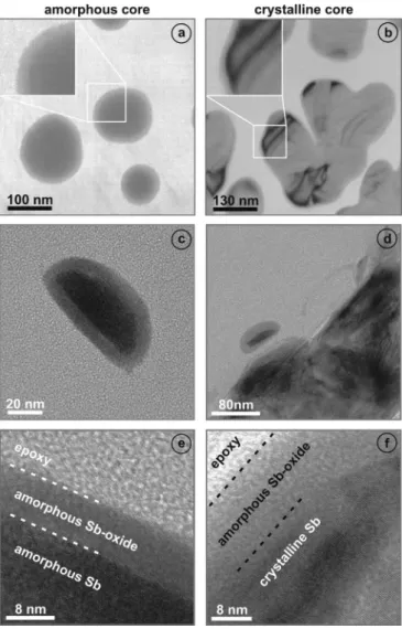
FIG. 4. TEM images of small, round, and amorphous antimony nanoparticles (left column), as well as larger antimony nanoparticles that are branched and crystalline (right column). Panels (a) and (b) show plane-view bright-field TEM images of amorphous and crystalline particles, respectively. While the particles on the left exhibit a mass thickness contrast pointing to an amorphous structure, TEM images of particles on the right feature dark contour lines, indicating crystallinity. Additionally, the magnified insets reveal that the particles are covered by an amorphous shell. Panels (c) and (d) each show cross-sectional bright-field TEM images, establishing that the particles are enclosed by the amorphous shell on all sides, including the side that is contacting the graphite substrate. Finally, (e) and (f) display high-resolution TEM images of the two particle types, demonstrating that the larger particles indeed have a crystalline core with an ordered atomic configuration, while the smaller ones are amorphous. Additionally, the amorphous character of the shell is confirmed through these high-resolution TEM images.
bright-field TEM images [Fig. 4(a)] and no indication of crystallinity based on the selected area diffraction and conver-gent beam diffraction studies, thus pointing to an amorphous structure. On the other hand, the branched particles of type (ii) (A > 25 000 nm2) produce dark contour lines in bright-field
TEM images [Fig. 4(b)], which are identified as bending contours and are clear indicators of crystallinity. However, in order to form a clear connection between nanoparticle structure and frictional behavior, a further aspect needs to be considered: As nanomanipulation experiments described in this paper are performed under ambient conditions for extended amounts of time, it is reasonable to expect that the Sb particles will be covered by an amorphous antimony oxide layer.30 This expectation is again confirmed by TEM images, where the oxide layer can be distinguished as a light grey shell around the nanoparticles in the insets of Figs.4(a) and4(b)
and the cross-sectional TEM images of Figs.4(c) and4(d). In addition, the high-magnification TEM images displayed in Figs.4(e)and4(f)provide further proof for the existence of an amorphous oxide shell around the Sb particles, which feature amorphous cores for particles of type (i) [Fig.4(e)] and crystalline cores for particles of type (ii) [Fig.4(f)].
With this knowledge, we can now discuss various scenarios that may explain the nonuniformity in frictional behavior. First, one could assume that the amorphous oxide layers for both particle types (i) and (ii) are chemically and structurally identical, since they are both formed by the oxidiation of pure antimony; this would imply that they must have matching frictional behavior, too. In this case, we have three options, as discussed in the following. First, we hypothesize that the bulk structure of the particles plays the dominant role in determining frictional behavior. This is, however, improbable, as the concept of lubrication is based on the supposition that even a monomolecular interface layer may completely shield adverse frictional properties of sliding surfaces. Using a similar argument, the effect of a potential variation in the average oxide layer thickness between crystalline and amorphous particles can be excluded as the main reason for the difference in frictional behavior In contrast, option two takes into account the change in the shape of the particles. For this scenario, we postulate that molecules that are naturally adsorbed under ambient conditions on the graphite surface become increasingly trapped in pockets at the circumference of the particles that form between individual branches of the larger crystalline samples. In accordance with previous theoretical work, such dirt molecules would then be expected to affect frictional behavior.37–39 While this effect may be contributing, it would be surprising if it could fully explain the observed threefold increase in frictional resistance, as this increase is so remarkably high that one would assume the physical origin to be quite distinct. Finally, option three would also consider the change in the shape of the particles but attempt to correlate the length of the circumference with friction. However, as discussed in an earlier publication,30 increases in the total length of a particle’s circumference in its branched state are only modest compared to a perfectly round particle of the same contact area, rendering this option unlikely as well.
With previous scenarios being insufficient at best, we must change our main assumption about the identity of the oxide
layers for type (i) and type (ii) particles, which would then naturally lead to varying frictional behavior between the two particle types. Such differences in the surface layers are, in fact, likely and can be explained by structural and/or stoichiometric variations between the type of antimony oxide that grows on amorphous particles and the one that grows on crystalline particles. Variations in structure and/or stoichiometry would alter the atomic-scale surface potential of antimony oxide, thus leading to differences in frictional behavior, because nanoscale friction between two surfaces in dry contact is determined by the characteristics of the involved surface potentials. In addition, the possibility that the antimony oxide layers that grow on crystalline and amorphous particles may feature different levels of atomic roughness needs to be considered, thereby taking into account that recent theoretical efforts have revealed that this interfacial property significantly influences frictional behavior on the nanoscale.40The fact that antimony oxide occurs in several different forms with fundamentally different stoichiometric compositions (such as Sb2O3, Sb2O4,
and Sb2O5) further corroborates the presumed validity of
this scenario.41 If true, these findings lead to the interesting consequence that thin amorphous layers formed by oxidation from the same pure metal at identical ambient conditions may still exhibit significantly different surface properties in terms of structure and chemistry.
IV. CONCLUSIONS
In this paper, we presented an experimental investigation of the contact area dependence of frictional properties associated with antimony nanoparticles on graphite over a wide size range from 2000 nm2 to 120 000 nm2, with nanomanipulation
ex-periments conducted using dynamic- and contact-mode AFM approaches revealing linear dependencies of threshold power dissipation and frictional force on contact area. However,
both the required power for particle movement, as well as the associated frictional forces per contact area, have been found to increase by a factor of three around a particle size of about 20 000 nm2, simultaneously with a phase transition
from amorphous to crystalline within the particles. Varia-tions in the stoichiometric composition and structure of the amorphous oxide layer covering the two types of Sb particles are hypothesized to be mainly responsible for this dramatic difference in their frictional properties. It must be emphasized that while it is beyond the scope of this work to pinpoint a specific mechanism as the definite reason for the noteworthy experimental observation reported here, differences induced in the atomic-scale surface potential of antimony oxide surfaces on amorphous and crystalline nanoparticles through structural and/or stoichiometric variations would certainly result in differing frictional behavior. Regardless of the exact physical mechanisms involved, the presented results are expected to lead to further experimental and theoretical investigations of the effect of interfacial properties on friction at the nanoscale.
ACKNOWLEDGMENTS
TEM measurements have been performed using an in-strument at the Institute of Physics of the Humboldt Uni-versity in Berlin, Germany. Primary financial support was provided by the National Science Foundation through the Yale Materials Research Science and Engineering Center (Grants No. MRSEC DMR-1119826 and No. DMR-0520495). In addition, C.R. received a personal stipend from the Deutsche Forschungsgemeinschaft (Grant No. Ri 1832/1-1) while carrying out parts of this study, and M.Z.B. gratefully acknowledges support from the Marie Curie Actions of the European Commission’s FP7 Program in the form of a Career Integration Grant (Grant No. PCIG12-GA-2012-333843).
*Present address: Fritz-Haber-Institut der Max-Planck-Gesellschaft, Faradayweg 4-6, 14195 Berlin, Germany.
†Corresponding author: [email protected]
1B. Bhushan, Nanotribology and Nanomechanics: An Introduction (Springer, Berlin, 2005).
2E. Gnecco and E. Meyer, Fundamentals of Friction and Wear on
the Nanoscale (Springer, Berlin, 2007).
3C. M. Mate, G. M. McClelland, R. Erlandsson, and S. Chiang,Phys.
Rev. Lett. 59, 1942 (1987).
4G. Binnig, C. F. Quate, and C. Gerber,Phys. Rev. Lett. 56, 930
(1986).
5U. D. Schwarz, O. Zworner, P. Koster, and R. Wiesendanger,Phys.
Rev. B 56, 6987 (1997).
6S. Morita, S. Fujisawa, and Y. Sugawara,Surf. Sci. Rep. 23, 1
(1996).
7R. Luthi, E. Meyer, M. Bammerlin, L. Howald, H. Haefke, T. Lehmann, C. Loppacher, H. J. Guntherodt, T. Gyalog, and H. Thomas,J. Vac. Sci. Technol. B 14, 1280 (1996).
8A. Socoliuc, R. Bennewitz, E. Gnecco, and E. Meyer,Phys. Rev.
Lett. 92, 134301 (2004).
9H. Bluhm, U. D. Schwarz, and K. P. Meyer,Appl. Phys. A 61, 525
(1995).
10H. Bluhm, U. D. Schwarz, and R. Wiesendanger,Phys. Rev. B 57,
161 (1998).
11N. N. Gosvami, T. Filleter, P. Egberts, and R. Bennewitz,Tribol.
Lett. 39, 19 (2010).
12T. Filleter, J. L. McChesney, A. Bostwick, E. Rotenberg, K. V. Emtsev, Th. Seyller, K. Horn, and R. Bennewitz,Phys. Rev. Lett. 102, 086102 (2009).
13C. Lee, Q. Y. Li, W. Kalb, X. Z. Liu, H. Berger, R. W. Carpick, and J. Hone,Science 328, 76 (2010).
14R. W. Carpick, N. Agrait, D. F. Ogletree, and M. Salmeron,
J. Vac. Sci. Technol. B 14, 1289 (1996).
15M. Enachescu, R. J. A. van den Oetelaar, R. W. Carpick, D. F. Ogletree, C. F. J. Flipse, and M. Salmeron, Phys. Rev. Lett. 81, 1877 (1998).
16E. Gnecco, R. Bennewitz, T. Gyalog, Ch. Loppacher, M. Bammerlin, E. Meyer, and H. J. G¨untherodt,Phys. Rev. Lett. 84, 1172 (2000).
17M. Evstigneev, A. Schirmeisen, L. Jansen, H. Fuchs, and P. Reimann, Phys. Rev. Lett. 97, 240601 (2006).
18X. Y. Zhao, M. Hamilton, W. G. Sawyer, and S. S. Perry,Tribol.
19L. Jansen, H. Holscher, H. Fuchs, and A. Schirmeisen,Phys. Rev.
Lett. 104, 256101 (2010).
20J. A. Ruan and B. Bhushan,J. Appl. Phys. 76, 5022 (1994). 21N. Sasaki, K. Kobayashi, and M. Tsukada,Phys. Rev. B 54, 2138
(1996).
22H. Holscher, U. D. Schwarz, and R. Wiesendanger,Europhys. Lett.
36, 19 (1996).
23H. Holscher, U. D. Schwarz, O. Zworner, and R. Wiesendanger,
Phys. Rev. B 57, 2477 (1998).
24M. Liley, D. Gourdon, D. Stamou, U. Meseth, T. M. Fischer, C. Lautz, H. Stahlberg, H. Vogel, N. A. Burnham, and C. Duschl,
Science 280, 273 (1998).
25M. Dienwiebel, G. S. Verhoeven, N. Pradeep, J. W. M. Frenken, J. A. Heimberg, and H. W. Zandbergen,Phys. Rev. Lett. 92, 126101 (2004).
26A. Schirmeisen and U. D. Schwarz,Chem. Phys. Chem. 10, 2373
(2009).
27C. Ritter, M. Heyde, B. Stegemann, K. Rademann, and U. D. Schwarz,Phys. Rev. B 71, 085405 (2005).
28D. Dietzel, T. Monninghoff, L. Jansen, H. Fuchs, C. Ritter, U. D. Schwarz, and A. Schirmeisen,J. Appl. Phys. 102, 084306 (2007).
29D. Dietzel, C. Ritter, T. M¨onninghoff, H. Fuchs, A. Schirmeisen, and U. D. Schwarz,Phys. Rev. Lett. 101, 125505 (2008).
30D. Dietzel, T. M¨onninghoff, C. Herding, M. Feldmann, H. Fuchs, B. Stegemann, C. Ritter, U. D. Schwarz, and A. Schirmeisen,Phys. Rev. B 82, 035401 (2010).
31D. Dietzel, M. Feldmann, C. Herding, U. D. Schwarz, and A. Schirmeisen,Tribol. Lett. 39, 273 (2010).
32B. Stegemann, C. Ritter, B. Kaiser, and K. Rademann, J. Phys.
Chem. B 108, 14292 (2004).
33M. Heyde, K. Rademann, B. Cappella, M. Geuss, H. Sturm, T. Spangenberg, and H. Niehus,Rev. Sci. Instrum. 72, 136 (2001).
34C. Ritter, M. Heyde, U. D. Schwarz, and K. Rademann,Langmuir
18, 7798 (2002).
35D. A. Aruliah, M. H. Muser, and U. D. Schwarz,Phys. Rev. B 71,
085406 (2005).
36D. Dietzel, M. Feldmann, H. Fuchs, U. D. Schwarz, and A. Schirmeisen,Appl. Phys. Lett. 95, 053104 (2009).
37G. He, M. H. Muser, and M. O. Robbins, Science 284, 1650
(1999).
38M. H. Muser, L. Wenning, and M. O. Robbins,Phys. Rev. Lett. 86,
1295 (2001).
39L. Wenning and M. H. Muser,Europhys. Lett. 54, 693 (2001). 40Y. Mo and I. Szlufarska,Nature (London) 457, 1116 (2009). 41N. N. Greenwood and A. Earnshaw, Chemistry of the Elements