A Performance Comparison of Polar Codes with
Convolutional Turbo Codes
a thesis
submitted to the department of electrical and
electronics engineering
and the institute of engineering and sciences
of bilkent university
in partial fulfillment of the requirements
for the degree of
master of science
By
¨
Ust¨
un ¨
Ozg¨
ur
November 2009
I certify that I have read this thesis and that in my opinion it is fully adequate, in scope and in quality, as a thesis for the degree of Master of Science.
Prof. Dr. Erdal Arıkan(Supervisor)
I certify that I have read this thesis and that in my opinion it is fully adequate, in scope and in quality, as a thesis for the degree of Master of Science.
Assist. Prof. Dr. Defne Akta¸s
I certify that I have read this thesis and that in my opinion it is fully adequate, in scope and in quality, as a thesis for the degree of Master of Science.
Assoc. Prof. Dr. Ali ¨Ozg¨ur Yılmaz
Approved for the Institute of Engineering and Sciences:
Prof. Dr. Mehmet Baray
ABSTRACT
A Performance Comparison of Polar Codes with
Convolutional Turbo Codes
¨
Ust¨
un ¨
Ozg¨
ur
M.S. in Electrical and Electronics Engineering
Supervisor: Prof. Dr. Erdal Arıkan
November 2009
Polar codes introduced recently by Arıkan are the first low-complexity codes achieving symmetric capacity for arbitrary binary-input discrete memoryless channels (B-DMCs). Although being theoretically significant, their practical sig-nificance is an issue that has not yet been fully explored. Previous studies have compared polar codes with Reed-Muller codes, where it was found that polar codes can outperform them. In this thesis, to investigate how polar codes per-form against state-of-the-art forward error correction (FEC) codes used in prac-tice, we implement a IEEE 802.16 based link-level Worldwide Interoperability for Microwave Access (WiMAX) simulator which incorporates several WiMAX FEC options, and polar codes. IEEE 802.16 standards family define standards for current and next generation broadband wireless access, which will make high data rate multimedia applications in mobile environments a reality. Next genera-tion broadband access standard, pursued by the IEEE 802.16 Task Group m is a work in progress, and requires even more sophisticated error correction schemes so that higher throughput, better QOS, higher mobilities, wider ranges and lower latencies are supported. We perform performance comparison simulations with
the convolutional turbo codes (CTC) configurations defined in IEEE 802.16e to see how much of a performance gap exists between polar codes and CTCs. The main findings of the thesis are that, although the polar codes achieve capacity for specific conditions, as expected, for the code lengths and channel conditions we have simulated, the performance of them cannot compete with that of the CTCs with equivalent rates and lengths. It remains a task to see whether po-lar codes can achieve simipo-lar performances with CTCs when used as component codes in other configurations and aid in the advancement of new communication technologies.
Keywords: WirelessMAN, WirelessMAN-OFDMA, IEEE 802.16e, IEEE
802.16m, physical layer technologies, polar codes, convolutional turbo codes, WiMAX, WirelessMAN-OFDMA Simulator, MIMO, Reed-Muller Codes, Per-formance Comparison
¨
OZET
KUTUPLAS
¸MA KODLARININ EVR˙IS
¸ ˙IML˙I TURBO KODLAR
˙ILE BAS¸ARIM KARS¸ILAS¸TIRMASI
¨
Ust¨
un ¨
Ozg¨
ur
Elektrik ve Elektronik M¨
uhendisli˘
gi B¨
ol¨
um¨
u Y¨
uksek Lisans
Tez Y¨
oneticisi: Prof. Dr. Erdal Arıkan
Kasım 2009
Yakın bir tarihte Arıkan tarafından tanıtılan, ikili ayrık hafızasız kanallar i¸cin simetrik kapasiteye ula¸stı˘gı kanıtlanan ilk ileri hata d¨uzeltme y¨ontemi olan ku-tupla¸sma kodlarının teorik ¨onemi g¨osterilmi¸s olsa da, pratikte bu kodların ¨onemi
daha tam olarak ara¸stırılmı¸s durumda bulunmamaktadır. Onceki ¸calı¸smalar¨
kutupla¸sma kodlarının Reed-Muller kodlarından daha y¨uksek performans
or-taya koydu˘gunu g¨ostermektedir. Bu tezde, kutupla¸sma kodlarının en geli¸smi¸s
ileri hata d¨uzeltme kodları kar¸sısında nasıl bir ba¸sarım g¨osterdi˘gini incelemek amacıyla IEEE 802.16e PHY (fiziksel) seviye belirlemesi (spesifikasyonu) tabanlı
ve WiMAX onaylamasıyla (sertifikasyonuyla) uyumlu bir ba˘glantı seviyesi
ben-zetici (simulat¨or) ger¸cekle¸stirilmi¸stir ve bu benzetici i¸cerisine WiMAX ileri hata
d¨uzeltme kodları ve kutupla¸sma kodları entegre edilmi¸stir. IEEE 802.16
stan-dartları ailesi g¨uncel ve sonraki nesil geni¸sbant kablosuz eri¸sim i¸cin
standart-lar tanımlayarak, y¨uksek veri hızı gerektiren ¸cokluortam uygulamalarının mobil
ortamlarda kullanımını olanaklı kılmayı ama¸clamaktadır. IEEE 802.16 G¨orev
Grubu m tarafından geli¸stirilmekte olan sonraki nesil geni¸sbant eri¸sim standardı daha y¨uksek aktarım hızı, daha iyi servis kalitesi (QoS), daha y¨uksek mobilite,
data geni¸s alan ve daha d¨u¸s¨uk gecikme deste˘gi ama¸cladı˘gı i¸cin hata d¨uzeltme y¨ontemlerinde ¨onceki standartlara g¨ore daha geli¸smi¸s tasarımlar gerektirmekte-dir. Tezde kutupla¸sma kodlarının IEEE 802.16e standardı dahilinde tanımlanan CTC d¨uzenle¸simleriyle ba¸sarım kar¸sıla¸stırması yapıldı. Tezin genel sonu¸cları ¸su ¸sekilde ¨ozetlenebilir: Kutupla¸sma kodları her ne kadar bahsedilen ko¸sullarda ka-pasiteye ula¸ssa da bu kodların ba¸sarımı, benzetimi yapılan kod uzunluk ve oran-larında ve benzetim ortamoran-larında, CTC kodlarının ba¸sarımıyla yarı¸samadı. Ku-tupla¸sma kodlarının ¨o˘ge kodlar olarak yeni kod d¨uzenle¸simlerinde kullanılması durumunda nasıl bir ba¸sarım g¨osterece˘gi ve yeni ileti¸sim teknolojilerine nasıl katkı sa˘glayabilece˘gi gelecek ¸calı¸smaların konusunu olu¸sturacaktır.
Anahtar Kelimeler: WirelessMAN, WirelessMAN-OFDMA, IEEE 802.16e, IEEE 802.16m, fiziksel seviye teknolojileri, kutupla¸sma kodları, evri¸simli turbo kod-lar,WiMAX, WirelessMAN-OFDMA Benzeticisi, MIMO, Reed-Muller Kodları, Ba¸sarım Kar¸sıla¸stırması
ACKNOWLEDGMENTS
I would like to thank my advisor Prof. Erdal Arıkan for his constant guidance and support during my studies and graduate education. Definitely the most exceptional person I have known, he is a man unmatched in intelligence and knowledge, yet so humble, kind and helpful all the time. More than an advisor, he has at times been like a father to me, always tolerating and forgiving. I regret that I have not lived upto his exceptations and possibly caused loss of time of this great man, which could otherwise be spent more efficiently without doubt.
I would like to thank my family, my mother Reyhan and my grandparents
S¸¨ukran and ˙Ibrahim for always believing in me no matter what. They have been
my constant supporters and without their support, I would not have endured this process.
I would like to thank all my friends, especially Damla Ate¸s, Can Bal and
Ozan Do˘gu Tuna for their endless support and belief in me. Even though I
believe they base their beliefs on history rather than present, I too hope that future will resemble history much more than present. I would like to thank all my past teachers, and all other people who have passed through my life.
I would also like to thank Assist. Prof. Defne Akta¸s and Assoc. Prof. Ali ¨
Ozg¨ur Yılmaz for serving as members of my thesis committee, accepting my
I would like to thank Iterative Solutions for providing the Iterative Solutions
Coded Modulation Library (CML)1 which we use to integrate the WiMAX CTC
codes in our simulator. I would like to thank Prof. Arıkan for providing the source code used for polar code support in our simulator.
Last, but not the least, I would like to thank T ¨UB˙ITAK for providing financial assistance for the polar coding project involving polar codes and throughout my graduate studies.
Contents
TABLE OF CONTENTS ix
LIST OF FIGURES xiv
LIST OF TABLES xxvi
PRELIMINARIES xxix
1 INTRODUCTION 1
2 IEEE 802.16 FAMILY OF STANDARDS AND WiMAX 5
2.1 History and Future of IEEE 802.16 Standards and WiMAX . . . . 6
2.1.1 Notable IEEE 802.16 Standards . . . 6
2.1.2 WiMAX Certification . . . 7
2.1.3 Roadmap of IEEE 802.16 and WiMAX . . . 8
2.2 PHY LAYER OF WirelessMAN-OFDMA . . . 9
2.2.1.1 Subchannelization . . . 12
2.2.1.2 Burst Construction and Burst Profile Selection . 13 2.2.1.3 Burst Zone . . . 16
2.2.1.4 Data Mapping Through Slots . . . 16
2.2.2 Channel Encoding . . . 18
2.2.2.1 Randomization . . . 18
2.2.2.2 FEC Coding . . . 18
2.2.2.2.1 Convolutional Encoding . . . 20
2.2.2.2.2 Block Turbo Codes . . . 20
2.2.2.2.3 CTCs . . . 21 2.2.2.2.4 LDPC . . . 22 2.2.2.3 Interleaving . . . 23 2.2.2.4 Modulation . . . 25 2.2.3 MIMO . . . 26 3 POLAR CODES 30 3.1 Preliminaries . . . 30 3.2 Overview . . . 31 3.3 Channel Transformation . . . 33
3.5 Polar Coding Revisited: Comparison with Reed-Muller Codes . . 38
3.6 Decoding . . . 42
4 PHY LAYER SIMULATOR 44 4.1 Simulation Chain . . . 44 4.1.1 Simulator Blocks . . . 46 4.1.1.1 FEC . . . 48 4.1.1.2 Subcarrier Allocations . . . 49 4.1.1.3 Channel Model . . . 51 4.2 Simulation Environment . . . 53
4.2.1 Parameters of the Simulator . . . 53
4.2.2 Simulation Parameters . . . 54
4.2.2.1 Primitive and Derived Parameters . . . 57
4.2.3 Simulation Assumptions . . . 60
4.2.4 Simulation Performance Metrics . . . 61
5 SIMULATION RESULTS AND ANALYSIS 64 5.1 SISO Results . . . 66
5.1.1 Results with QPSK Modulation in a SISO Setting . . . 67
5.1.1.1 Comparison of Codes with Coding Rate = 1/2 . 68
5.1.2 Results with 16-QAM Modulation in a SISO Setting . . . 79
5.1.2.1 Comparison of Codes with Coding Rate = 1/2 . 79
5.1.2.2 Comparison of Codes with Coding Rate = 3/4 . 79
5.2 MIMO 2x2 Results . . . 89
5.2.1 Results with QPSK Modulation in a MIMO 2x2 Setting . 89
5.2.1.1 Comparison of Codes with Coding Rate = 1/2 . 89
5.2.1.2 Comparison of Codes with Coding Rate = 3/4 . 93
5.2.2 Results with 16-QAM Modulation in a MIMO 2x2 Setting 97
5.2.2.1 Comparison of Codes with Coding Rate = 1/2 . 97
5.2.2.2 Comparison of Codes with Coding Rate = 3/4 . 101
5.3 Analysis of Performance Gap Between the Polar Codes and CTCs 105
5.3.1 Improvement Through Selection of Frozen Positions . . . . 106
5.4 Comparison of Similar Scenarios under Different MIMO Schemes
and Channel Conditions . . . 110
5.4.1 Effect of Channel in Similar Code Configurations and
MIMO Settings . . . 110
5.4.2 Effect of MIMO Scheme in Similar Code Configurations
and Channels . . . 115
5.5 Effect of PUSC on Performance . . . 118
APPENDIX 125
A PERFORMANCE IMPROVEMENTS USING MEX FILES 125
A.1 Summary . . . 125
A.2 Results . . . 126
B ALLOWED BURST PROFILE CONFIGURATIONS 129
List of Figures
2.1 Sample PUSC-DL Subchannel Formations for NF F T = 1024 . . . 14
2.2 Sample FUSC Subchannel Formations for NF F T = 1024 – Red
dashed vertical lines show the group demarkings . . . 14
2.3 Data Stream and Its Randomized Version . . . 19
2.4 Block diagram depicting the encoding process for Convolutional
Encoder (courtesy of [1]) . . . 21
2.5 CTC Encoder Diagram(courtesy of [1]) . . . 22
2.6 Constellations for Different Mappings (Numbers signify the
deci-mal notation of bit sequences, added by 1) . . . 25
3.1 Raw Channel and Initial Transformation to Form Size-2
Super-channel (from [2]) . . . 31
3.2 Recursive Construction of the Combined Channel of Size N (from[2]) 35
3.3 Polarization of Channels as n : 0 → 6 with Slanted Numbers
Signifying the Position with Reverse Sorted Symmetric Capacity – the higher the more reliable channel . . . 37
4.1 Screenshot of the IEEE 802.16-2009 Simulator GUI . . . 45
4.2 Block Diagram of the Simulator . . . 47
4.3 Default Allocation of Bursts for NF F T = 1024 . . . 50
4.4 Screenshot of the Burst Allocation GUI . . . 51
4.5 Manually Configured Burst Allocation . . . 52
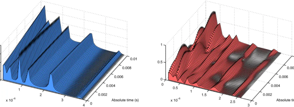
4.6 Channel instances for the Modified Pedestrian B Model (left) at v = 5 km/h and Modified Vehicular A Model (right) at v = 60 km/h . . . 53
5.1 Comparison of Coded (Rate = 1/2) and Uncoded Schemes Under AWGN Channel with QPSK Modulation . . . 69
5.2 BER vs Eb/No Performance Curve for Rate 1/2 Polar and CTC Codes at Two Different Code Lengths in an AWGN Channel in a SISO Setting, with QPSK Modulation . . . 69
5.3 FER vs Eb/No Performance Curve for Rate 1/2 Polar and CTC Codes at Two Different Code Lengths in an AWGN Channel in a SISO Setting, with QPSK Modulation . . . 70
5.4 Comparison of Coded (Rate = 1/2) and Uncoded Schemes Under Rayleigh Channel with QPSK Modulation . . . 70
5.5 BER vs Eb/No Performance Curve for Rate 1/2 Polar and CTC Codes at Two Different Code Lengths in Rayleigh Channel in a SISO Setting, with QPSK Modulation . . . 71
5.6 FER vs Eb/No Performance Curve for Rate 1/2 Polar and CTC
Codes at Two Different Code Lengths in Rayleigh Channel in a
SISO Setting, with QPSK Modulation . . . 71
5.7 BER vs Eb/No Performance Curve for Rate 1/2 Polar and CTC
Codes at Two Different Code Lengths in Modified Pedestrian B
Channel (v = 5km/h) in a SISO Setting, with QPSK Modulation 72
5.8 FER vs Eb/No Performance Curve for Rate 1/2 Polar and CTC
Codes at Two Different Code Lengths in Modified Pedestrian B
Channel (v = 5km/h) in a SISO Setting, with QPSK Modulation 72
5.9 BER vs Eb/No Performance Curve for Rate 1/2 Polar and CTC
Codes at Two Different Code Lengths in Modified Vehicular A Channel (v = 60km/h) in a SISO Setting, with QPSK Modulation 73
5.10 FER vs Eb/No Performance Curve for Rate 1/2 Polar and CTC
Codes at Two Different Code Lengths in Modified Vehicular A Channel (v = 60km/h) in a SISO Setting, with QPSK Modulation 73
5.11 Comparison of Coded (Rate = 3/4) and Uncoded Schemes Under
AWGN Channel with QPSK Modulation . . . 74
5.12 BER vs Eb/No Performance Curve for Rate 3/4 Polar and CTC
Codes at Two Different Code Lengths in an AWGN Channel in a
SISO Setting, with QPSK Modulation . . . 75
5.13 Rate 3/4 Polar and CTC Codes at Two Different Code Lengths
in an AWGN Channel in a SISO Setting, with QPSK Modulation 75
5.14 BER vs Eb/No Performance Curve for Rate 3/4 Polar and CTC
Codes at Two Different Code Lengths in Rayleigh Channel in a
5.15 FER vs Eb/No Performance Curve for Rate 3/4 Polar and CTC
Codes at Two Different Code Lengths in Rayleigh Channel in a
SISO Setting, with QPSK Modulation . . . 76
5.16 BER vs Eb/No Performance Curve for Rate 3/4 Polar and CTC
Codes at Two Different Code Lengths in Modified Pedestrian B
Channel (v = 5km/h) in a SISO Setting, with QPSK Modulation 77
5.17 FER vs Eb/No Performance Curve for Rate 3/4 Polar and CTC
Codes at Two Different Code Lengths in Modified Pedestrian B
Channel (v = 5km/h) in a SISO Setting, with QPSK Modulation 77
5.18 BER vs Eb/No Performance Curve for Rate 3/4 Polar and CTC
Codes at Two Different Code Lengths in Modified Vehicular A Channel (v = 60km/h) in a SISO Setting, with QPSK Modulation 78
5.19 FER vs Eb/No Performance Curve for Rate 3/4 Polar and CTC
Codes at Two Different Code Lengths in Modified Vehicular A Channel (v = 60km/h) in a SISO Setting, with QPSK Modulation 78
5.20 BER vs Eb/No Performance Curve for Rate 1/2 Polar and CTC
Codes at Two Different Code Lengths in an AWGN Channel in a
SISO Setting, with 16-QAM Modulation . . . 80
5.21 FER vs Eb/No Performance Curve for Rate 1/2 Polar and CTC
Codes at Two Different Code Lengths in an AWGN Channel in a
SISO Setting, with 16-QAM Modulation . . . 80
5.22 BER vs Eb/No Performance Curve for Rate 1/2 Polar and CTC
Codes at Two Different Code Lengths in Rayleigh Channel in a
5.23 FER vs Eb/No Performance Curve for Rate 1/2 Polar and CTC
Codes at Two Different Code Lengths in Rayleigh Channel in a
SISO Setting, with 16-QAM Modulation . . . 81
5.24 BER vs Eb/No Performance Curve for Rate 1/2 Polar and CTC
Codes at Two Different Code Lengths in Modified Pedestrian B Channel (v = 5km/h) in a SISO Setting, with 16-QAM Modulation 82
5.25 FER vs Eb/No Performance Curve for Rate 1/2 Polar and CTC
Codes at Two Different Code Lengths in Modified Pedestrian B Channel (v = 5km/h) in a SISO Setting, with 16-QAM Modulation 82
5.26 BER vs Eb/No Performance Curve for Rate 1/2 Polar and CTC
Codes at Two Different Code Lengths in Modified Vehicular A Channel (v = 60km/h) in a SISO Setting, with 16-QAM Modulation 83
5.27 FER vs Eb/No Performance Curve for Rate 1/2 Polar and CTC
Codes at Two Different Code Lengths in Modified Vehicular A Channel (v = 60km/h) in a SISO Setting, with 16-QAM Modulation 83
5.28 BER vs Eb/No Performance Curve for Rate 3/4 Polar and CTC
Codes at Two Different Code Lengths in an AWGN Channel in a
SISO Setting, with 16-QAM Modulation . . . 85
5.29 FER vs Eb/No Performance Curve for Rate 1/2 Polar and CTC
Codes at Two Different Code Lengths in an AWGN Channel in a
SISO Setting, with 16-QAM Modulation . . . 85
5.30 BER vs Eb/No Performance Curve for Rate 3/4 Polar and CTC
Codes at Two Different Code Lengths in an AWGN Channel in a
5.31 FER vs Eb/No Performance Curve for Rate 3/4 Polar and CTC
Codes at Two Different Code Lengths in Rayleigh Channel in a
SISO Setting, with 16-QAM Modulation . . . 86
5.32 BER vs Eb/No Performance Curve for Rate 3/4 Polar and CTC
Codes at Two Different Code Lengths in Modified Pedestrian B Channel (v = 5km/h) in a SISO Setting, with 16-QAM Modulation 87
5.33 FER vs Eb/No Performance Curve for Rate 3/4 Polar and CTC
Codes at Two Different Code Lengths in Modified Pedestrian B Channel (v = 5km/h) in a SISO Setting, with 16-QAM Modulation 87
5.34 BER vs Eb/No Performance Curve for Rate 3/4 Polar and CTC
Codes at Two Different Code Lengths in Modified Vehicular A Channel (v = 60km/h) in a SISO Setting, with 16-QAM Modulation 88
5.35 FER vs Eb/No Performance Curve for Rate 3/4 Polar and CTC
Codes at Two Different Code Lengths in Modified Vehicular A Channel (v = 60km/h) in a SISO Setting, with 16-QAM Modulation 88
5.36 BER vs Eb/No Performance Curve for Rate 1/2 Polar and CTC
Codes at Two Different Code Lengths in Rayleigh Channel in a
MIMO 2x2 Setting, with QPSK Modulation . . . 90
5.37 FER vs Eb/No Performance Curve for Rate 1/2 Polar and CTC
Codes at Two Different Code Lengths in Rayleigh Channel in a
MIMO 2x2 Setting, with QPSK Modulation . . . 90
5.38 BER vs Eb/No Performance Curve for Rate 1/2 Polar and CTC
Codes at Two Different Code Lengths in Mod. Pedestrian B
5.39 FER vs Eb/No Performance Curve for Rate 1/2 Polar and CTC
Codes at Two Different Code Lengths in Mod. Pedestrian B
Chan-nel in a MIMO 2x2 Setting, with QPSK Modulation . . . 91
5.40 BER vs Eb/No Performance Curve for Rate 1/2 Polar and CTC
Codes at Two Different Code Lengths in Mod. Vehicular A
Chan-nel in a MIMO 2x2 Setting, with QPSK Modulation . . . 92
5.41 FER vs Eb/No Performance Curve for Rate 1/2 Polar and CTC
Codes at Two Different Code Lengths in Mod. Vehicular A
Chan-nel in a MIMO 2x2 Setting, with QPSK Modulation . . . 92
5.42 BER vs Eb/No Performance Curve for Rate 3/4 Polar and CTC
Codes at Two Different Code Lengths in Rayleigh Channel in a
MIMO 2x2 Setting, with QPSK Modulation . . . 93
5.43 FER vs Eb/No Performance Curve for Rate 3/4 Polar and CTC
Codes at Two Different Code Lengths in Rayleigh Channel in a
MIMO 2x2 Setting, with QPSK Modulation . . . 94
5.44 BER vs Eb/No Performance Curve for Rate 3/4 Polar and CTC
Codes at Two Different Code Lengths in Mod. Pedestrian B
Chan-nel in a MIMO 2x2 Setting, with QPSK Modulation . . . 94
5.45 FER vs Eb/No Performance Curve for Rate 3/4 Polar and CTC
Codes at Two Different Code Lengths in Mod. Pedestrian B
Chan-nel in a MIMO 2x2 Setting, with QPSK Modulation . . . 95
5.46 BER vs Eb/No Performance Curve for Rate 3/4 Polar and CTC
Codes at Two Different Code Lengths in Mod. Vehicular A
5.47 FER vs Eb/No Performance Curve for Rate 3/4 Polar and CTC
Codes at Two Different Code Lengths in Mod. Vehicular A
Chan-nel in a MIMO 2x2 Setting, with QPSK Modulation . . . 96
5.48 BER vs Eb/No Performance Curve for Rate 1/2 Polar and CTC
Codes at Two Different Code Lengths in Rayleigh Channel in a
MIMO 2x2 Setting, with 16 QAM Modulation . . . 98
5.49 FER vs Eb/No Performance Curve for Rate 1/2 Polar and CTC
Codes at Two Different Code Lengths in Rayleigh Channel in a
MIMO 2x2 Setting, with 16 QAM Modulation . . . 98
5.50 BER vs Eb/No Performance Curve for Rate 1/2 Polar and CTC
Codes at Two Different Code Lengths in Mod. Pedestrian B
Chan-nel in a MIMO 2x2 Setting, with 16 QAM Modulation . . . 99
5.51 FER vs Eb/No Performance Curve for Rate 1/2 Polar and CTC
Codes at Two Different Code Lengths in Mod. Pedestrian B
Chan-nel in a MIMO 2x2 Setting, with 16 QAM Modulation . . . 99
5.52 BER vs Eb/No Performance Curve for Rate 1/2 Polar and CTC
Codes at Two Different Code Lengths in Mod. Vehicular Channel
in a MIMO 2x2 Setting, with 16 QAM Modulation . . . 100
5.53 FER vs Eb/No Performance Curve for Rate 1/2 Polar and CTC
Codes at Two Different Code Lengths in Mod. Vehicular Channel
in a MIMO 2x2 Setting, with 16 QAM Modulation . . . 100
5.54 BER vs Eb/No Performance Curve for Rate 3/4 Polar and CTC
Codes at Two Different Code Lengths in Rayleigh Channel in a MIMO 2x2 Setting, with 16 QAM Modulation . . . 102
5.55 FER vs Eb/No Performance Curve for Rate 3/4 Polar and CTC
Codes at Two Different Code Lengths in Rayleigh Channel in a MIMO 2x2 Setting, with 16 QAM Modulation . . . 102
5.56 BER vs Eb/No Performance Curve for Rate 3/4 Polar and CTC
Codes at Two Different Code Lengths in Mod. Pedestrian B Chan-nel in a MIMO 2x2 Setting, with 16 QAM Modulation . . . 103
5.57 FER vs Eb/No Performance Curve for Rate 3/4 Polar and CTC
Codes at Two Different Code Lengths in Mod. Pedestrian B Chan-nel in a MIMO 2x2 Setting, with 16 QAM Modulation . . . 103
5.58 BER vs Eb/No Performance Curve for Rate 3/4 Polar and CTC
Codes at Two Different Code Lengths in Mod. Vehicular A Chan-nel in a MIMO 2x2 Setting, with 16 QAM Modulation . . . 104
5.59 FER vs Eb/No Performance Curve for Rate 3/4 Polar and CTC
Codes at Two Different Code Lengths in Mod. Vehicular A Chan-nel in a MIMO 2x2 Setting, with 16 QAM Modulation . . . 104
5.60 BER vs Eb/No: Improvement of Polar Code under AWGN
Chan-nel Through More Appropriate Frozen Bit Position Selection (Sc 1601 Refers to the Original Polar Code, Sc 1602 Refers to the Im-proved Polar Code (with Frozen Positions Changed to that of an AWGN Channel with 8 dB SNR), Sc 1605 refers to the reference CTC Code) . . . 107
5.61 FER vs Eb/No: Improvement of Polar Code under AWGN
Chan-nel Through More Appropriate Frozen Bit Position Selection (Sc 1601 Refers to the Original Polar Code, Sc 1602 Refers to the Im-proved Polar Cod (with Frozen Positions Changed to that of an AWGN Channel with 8 dB SNR), Sc 1605 refers to the reference CTC Code) . . . 108
5.62 BER vs Eb/No: Improvement of Polar Code under Rayleigh
Chan-nel Through More Appropriate Frozen Bit Position Selection (Sc 1701 Refers to the Original Polar Code, Sc 1704 Refers to the Im-proved Polar Code (with Frozen Positions Changed to that of an AWGN Channel with 8 dB SNR), Sc 1605 refers to the reference CTC Code) . . . 108
5.63 FER vs Eb/No: Improvement of Polar Code under Rayleigh
Chan-nel More Appropriate Frozen Bit Position Selection (Sc 1701 Refers to the Original Polar Code, Sc 1704 Refers to the Improved Polar Code (with Frozen Positions Changed to that of an AWGN Channel with 8 dB SNR), Sc 1605 refers to the reference CTC Code)109
5.64 Effect of Channel in Similar Code Configurations in a SISO Setting
with QPSK Modulation: BER vs Eb/No Plot . . . 112
5.65 Effect of Channel in Similar Code Configurations in a SISO Setting
with QPSK Modulation: FER vs Eb/No Plot . . . 112
5.66 Effect of Channel in Similar Code Configurations in a SISO Setting
with 16 QAM Modulation: BER vs Eb/No Plot . . . 113
5.67 Effect of Channel in Similar Code Configurations in a SISO Setting
5.68 Effect of Channel in Similar Code Configurations in a MIMO 2x2
Setting with 16 QAM Modulation: BER vs Eb/No Plot . . . 114
5.69 Effect of Channel in Similar Code Configurations in a MIMO 2x2
Setting with 16 QAM Modulation: FER vs Eb/No Plot . . . 114
5.70 Performance of Uncoded Modulation Under Rayleigh Channel with QPSK Modulation for SISO, MIMO 2x1 and MIMO 2x2
Antenna Schemes . . . 115
5.71 Effect of MIMO 2x2 Scheme for Similar Code Configurations in
Rayleigh Channel: BER vs Eb/No Plot . . . 116
5.72 Effect of MIMO 2x2 Scheme for Similar Code Configurations in
Rayleigh Channel: FER vs Eb/No Plot . . . 116
5.73 Effect of MIMO 2x2 Scheme for Similar Code Configurations in
Modified Vehicular A Channel: BER vs Eb/No Plot . . . 117
5.74 Effect of MIMO 2x2 Scheme for Similar Code Configurations in
Modified Vehicular A Channel: FER vs Eb/No Plot . . . 117
5.75 BER vs EbNo Performance of Two Code Configurations with PUSC Enabled and Disabled; under Mod. Ped B Channel for
SISO Scheme with QPSK Modulation . . . 119
5.76 FER vs EbNo Performance of Two Code Configurations with PUSC Enabled and Disabled; under Mod. Ped B Channel for
SISO Scheme with QPSK Modulation . . . 119
5.77 BER vs EbNo Performance of Two Code Configurations with PUSC Enabled and Disabled; under Mod. Ped B Channel for
5.78 FER vs EbNo Performance of Two Code Configurations with PUSC Enabled and Disabled; under Mod. Ped B Channel for
SISO Scheme with 16 QAM Modulation . . . 120
5.79 BER vs EbNo Performance of Two Code Configurations with PUSC Enabled and Disabled; under Mod. Ped B Channel for MIMO 2x2 Scheme with QPSK Modulation . . . 121
5.80 FER vs EbNo Performance of Two Code Configurations with PUSC Enabled and Disabled; under Mod. Ped B Channel for MIMO 2x2 Scheme with QPSK Modulation . . . 121
5.81 BER vs EbNo Performance of Two Code Configurations with PUSC Enabled and Disabled; under Mod. Ped B Channel for MIMO 2x2 Scheme with 16 QAM Modulation . . . 122
5.82 FER vs EbNo Performance of Two Code Configurations with PUSC Enabled and Disabled; under Mod. Ped B Channel for MIMO 2x2 Scheme with 16 QAM Modulation . . . 122
A.1 Gain Averages for Different Compilers . . . 127
A.2 Gain Averages for Different N Values . . . 127
List of Tables
2.1 The Effect of Interleaving Steps on the Index Number for a Code
Length of 192 in a 64-QAM Setting . . . 24
4.1 MEX File Performance Improvements Using Different Compilers . 48
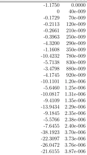
4.2 Power Delay Profile for the ITU Modified Pedestrian B Channel . 54
4.3 Power Delay Profile for the ITU Modified Vehicular A Channel . . 55
4.4 Common parameters for Bursts . . . 55
4.5 Individual Parameters for Each Burst . . . 55
4.6 Sampling factors for Different Bandwidths . . . 58
4.7 OFDMA Parameters for Different FFT Sizes . . . 60
5.1 Code Configurations for QPSK Modulation and Rate 1/2 . . . 66
5.2 Code Configurations for QPSK Modulation and Rate 3/4 . . . 66
5.3 Code Configurations for 16 QAM Modulation and Rate 1/2 . . . 66
5.4 Code Configurations for 16 QAM Modulation and Rate 3/4 . . . 67
A.2 Average Gain as Polar Code Length N Increases . . . 126 A.3 Average Gain as Trial Number Increases . . . 126
B.1 Convolutional Coding . . . 130
B.2 LDPC Block Sizes (n denotes the coded block length) . . . 131 B.3 CTC channel coding per modulation . . . 132
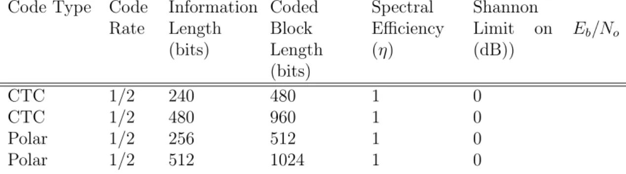
B.4 Equivalent Polar Code Configurations for the CTC Code Config-urations Above . . . 133
To my grandparents S
¸ ¨
ukran and ˙Ibrahim ¨
Ust¨
un. . .
PRELIMINARIES
Abbreviations and Acronyms
• AMC Adaptive Modulation and Coding • AMS Adaptive MIMO Switching
• AWGN Additive white Gaussian noise • BER Bit Error Rate
• BS Base Station
• CQI Channel Quality Indicator • CSI Channel State Information
• EMD 802.16m Evaluation Methodology Document • ESM Effective SINR Mapping
• IDFT Inverse Discrete Fourier Transform • LDPC Low Density Parity Check (Code) • MAP Maximum A Posteriori
• MIMO Multiple-Input Multiple-Output • MMIB Mean Mutual Information per Bit
• OFDM Orthogonal Frequency Division Multiplexing • OFDMA Orthogonal Frequency Division Multiple Access • PER Packet error rate
• PUSC Partial Usage of Subcarriers
• RBIR Received Bit Mutual Information Rate • SISO Single-Input Single-Output
• SNR Signal to Noise Ratio • SOFDMA Scalable OFDMA • STBC Space–time block code
• WiMAGIC Worldwide Interoperability Microwave Broadband Access Sys-tem for Next Generation Wireless Communications
• WiMAX Worldwide Interoperability for Microwave Access • MCS: Modulation Coding Scheme
Chapter 1
INTRODUCTION
Polar codes, recently introduced by Arıkan in [2] are the first low-complexity codes that theoretically achieve symmetric capacity of binary-input discrete memoryless channels (B-DMCs), however its practical value has not been inves-tigated yet. It is known that under certain conditions and decoding schemes, it outperforms Reed-Muller codes[3], however its performance advantage suggested that in its current state, it would not compete with state-of-the-art capacity achieving forward error correction (FEC) codes like convolutional turbo codes (CTCs) since CTCs outperform Reed-Muller codes by a wide margin, while the performance difference between the polar codes and the Reed-Muller codes are not that high. In this thesis, we mainly investigate how apart are the perfor-mance curves for polar codes so that we get an idea on how much polar codes should be improved from their current state to be useful in practical systems. To test the codes in a realistic environment, we decided to test the codes in a Worldwide Interoperability for Microwave Access (WiMAX) simulator, since it is an important standard for next generation broadband internet access.
Broadband internet access has become an indispensable part of our lives. With its mass adoption, the Internet has become the most important tool in
managing our lives: it has changed the way we work, the way we socialize, the way we communicate. Another important technology that has changed the way we live is that the mobile devices, cellular phones and laptop computers are now ubiquitous. The next paradigm shift in human evolution will happen when these two technologies fully merge; just like the biological evolution has provided us the basic communication tools, our sociological evolution has brought us more and more communication skills and it paves the way for a global human society.
Although there are alternatives to broadband wireless access (BWA) at the moment, the mission of obtaining true BWA has still not been met. By true BWA, we mean that users will have access to data rates that can meet the de-mands of multimedia applications. The need for high data-rate multimedia appli-cations is very important, since without those appliappli-cations, the devices through which we access the Internet will still be perceived as agents between us and the Internet. It will be when the devices provide such a realistic environment that its very presence will be forgotten that we will be seamlessly interacting online, every part of lives will be accompanied by a constant connection to the Internet superhighway; a future where every device we use is constantly online.
Of the current options, WiFi simply does not have the coverage to provide such a seamless connection everywhere, and pre-3G cellular technologies fail to provide any useful data rates. With the now becoming popular 3G technologies everywhere, and the emerging 4G technologies, broadband wireless access will be taken to a new level.
IEEE 802.16 standards enter the scene of networking as the perfect solution for providing BWA solutions. For 3G networks, Mobile WiMAX standard based on this family’s 2005e standard has been selected as an option, and its next-generation incarnation, IEEE 802.16m aims to satisfy the requirements of the next wave of high speed multimedia supporting wireless standards, the IMT-Advanced, i.e. 4G.
IEEE 802.16 and WiMAX standards do not only provide another option for BWA; but they even serve to a better cause. In under-developed and developing countries where even cellular and PSTN technologies have not been deployed, they will serve those countries as the sole Internet connection, and this will be a huge step forward in bringing the whole humanity the same set of tools and opportunities. Although the adoption seems at danger in developed countries due to the dominance of cellular operators which see LTE as the natural evolution path; WiMAX, with its open nature, will and should be the choice for other markets.
In this thesis, we implement a IEEE 802.16e simulator in MATLAB to per-form simulations in which we test the proposed options under different conditions. This standard has been finalized and its latest revisions have been merged into one document in IEEE 802.16-2009. The next step the IEEE 802.16 Techni-cal Working Group will take is IEEE 802.16m, in which even higher data rate applications with better quality of service (QoS) support will be provided.
Our main aim in this thesis was to provide new contributions to the ongoing standardization effort by seeing whether a newly proposed forward error correct-ing (FEC) technique introduced by Arıkan, polar codes, can be a usable FEC option as it is the first FEC scheme that achieves the symmetric capacity under conditions that will be explained in the relevant sections.
Chapter 2 presents the IEEE 802.16 family of standards and how the WiMAX certification was based upon them. It gives an overview of the history and future of these standards and introduces IEEE 802.16d, 802.16e and 802.16m.
In Chapter 3, we give a detailed description of the IEEE 802.16e simulator we have implemented. Since the options presented in IEEE 802.16 are various, we give detailed information regarding the choices, simplifications and assumptions we have used.
Chapter 4 gives information on polar codes; their construction and integra-tion into the IEEE 802.16 simulaintegra-tion chain. Addiintegra-tionally, we present how we form polar code configurations that match the Convolutional Turbo Code (CTC) configurations defined in the standard.
In Chapter 5, we give our results on comparing the polar codes and CTC schemes under different channel conditions and antenna settings.
Chapter 6 concludes, summarizing our results; and in Appendix, we give extra information regarding the supported modulation and coding schemes, a user guide on the simulator, and our results on optimization of the simulator using C files integrated into MATLAB.
Chapter 2
IEEE 802.16 FAMILY OF
STANDARDS AND WiMAX
IEEE 802 family of standards are a standards family of IEEE that focuses on various networking technologies such as personal, local and metropolitan area networks, namely PANS, LANs and MANs. These standards are maintained by several working groups each focusing on a different selection of standards under the direction of IEEE 802 LAN/MAN Standards Committee.
Of these family of standards, the most well-known ones are the 802.3 stan-dard, which standardizes the Ethernet technology, and standard families 802.11 on Wireless LANs and 802.15 on Wireless PANs, upon which respectively the WiFi certification and Bluetooth protocols are based.
IEEE 802.16, another subset of the IEEE 802 family, is itself a family of standards developed by the 802.16 Working Group. Its main aim is to develop wireless broadband standards for metropolitan area sized networks; hence its alternative name, “WirelessMAN”.
Within the working group for 802.16, there are several task groups each de-veloping a different 802.16 standard on a different topic. Some of these have completed their tasks, and some are still active. As of August 2009, the Wire-lessMAN website lists four active task groups, namely “License-Exempt Task Group”, “ Relay Task Group”, “Task Group m (TGm)” and the “Maintenance Task Group”. These groups are working on standards 802.16h, 802.16j, 802.16m and 802.16-2004 respectively, either working on drafts or amendments.
2.1
History and Future of IEEE 802.16
Stan-dards and WiMAX
2.1.1
Notable IEEE 802.16 Standards
The IEEE 802.16 Working Group was founded in 1999, and has since created several different standards for wireless MANs. The standards were aimed at fixed deployment scenarios initially, and the major product of that period was the standard 802.16-2004 (16d) published in 2004, a culmination of the pre-vious standards that far, supporting various frequency profiles (2-11 GHz and 10-66 GHz). [4]
A year later, this standard was amended by the work of ‘Task Group e’ in or-der to support mobile scenarios, and the new standard, accepted in 2005, which included corrections to, omissions from and amendments to 802.16-2004[5] was published as 802.16e-2005[6], in early 2006. This amendment is also known as “Mobile WirelessMAN”, although one should note that fixed communication sup-port still exists when the standards 2004 and 2005 are considered in conjunction [7].
Further amendments published as 802.16f and 802.16g, along with 802.16e-2005 and 802.16d-2004, and fixes have been finally merged into one document and recently published as 802.16-Rev2-2009, which supersedes previous standards.
2.1.2
WiMAX Certification
The IEEE 802.16 standards are responsible for specifying only the PHY and MAC layers of the air interface between a subscriber station and a base station; and as such, other issues for the system to be viable as a practical alternative, such as the end-to-end specification which determines the network architecture are not included.
Furthermore, probably for sake of completeness or political reasons (to ap-pease the proponents of various techniques) , the IEEE 802.16 standards include several optional choices for different building blocks, but the implementation of all of these is cumbersome for vendors, and a common subset of choices has to be selected.
Therefore, akin to the relationship between the 802.11 family of standards and the WiFi certification which is based on that family, the need for certification of products based on 802.16 standards has resulted in the emergence of WiMAX cer-tification, which is controlled by the industry led, non-profit “WiMAX Forum”. WiMAX Forum was established in 2003 with the mission to promote WiMAX as a technology based on air interface specifications as a subset of the IEEE 802.16 family of standards, complemented with a set of network specifications. Tasks within WiMAX are carried by its own working groups.
WiMAX stands for “Worldwide Interoperability for Microwave Access” and as its name implies, its main focus is on maintaining the conformance and in-teroperability of products so that vendor lock-in is prohibited and products of different vendors operate in harmony within a WiMAX ecosystem. The technical
working group states on the WiMAX Forum website that its main goal “is to develop technical product specifications and certification test suites for the air interface based on the OFDMA PHY, complementary to the IEEE 802.16 stan-dards, primarily for the purpose of interoperability and certification of Mobile Stations, Subscriber Stations and Base Stations conforming to the IEEE 802.16 standards.”.
Since there is more than one 802.16 standard, correspondingly, there are sev-eral WiMAX certifications. Fixed WiMAX is the one based on 802.16d-2004; and mobile WiMAX is the one based on 802.16e-2005. More precisely, the cer-tification based on 802.16e-2005, complemented with Network Profile 1 is called the Mobile WiMAX release 1 certification; and similarly, the certification based on 802.16Rev2-2009, is called the Mobile WiMAX release 1.5 certification.
As of October 2007, The ITU Radiocommunication Assembly recognizes Mo-bile WiMAX to be in the set of radio interface options for the IMT-2000 stan-dards. These standards are also called 3G standards, and aim to determine the specifications for mobile telecommunication systems requiring high-speed (broad-band) data rates.
2.1.3
Roadmap of IEEE 802.16 and WiMAX
The next generation of IEEE 802.16, 802.16m is currently being developed by the Task Group m. This standard is being prepared as an amendment to the previous standards, and therefore the previous standards will remain fixed and new contributions will be appended as additional chapters.
In parallel to the efforts of the Task Group m, the Mobile WiMAX release 2.0 certification is being prepared based on this new standard. As WiMAX has been recognized as a 3G technology, the aim of the WiMAX forum is to make the next
generation of WiMAX (also called WiMAX2) to be a part of the IMT-Advanced standards, better known in public as 4G.[8]
The key enhancements targeted in IEEE 802.16m are given in [9] as follows:
• Doubling relative throughput of a data only system compared to WirelessMAN-OFDMA, support of data rates of several hundreds of Mbit/s • Doubling relative sector throughput and increasing VoIP capacity by a
factor of 1.5
• Mobility support at speeds as high as 350 km/h • Improved cell coverage, upto a radius of 100 km • Increased spectral efficiency, decreased latencies
2.2
PHY LAYER OF WirelessMAN-OFDMA
IEEE 802.16-2009 standard specifies the air interface for broadband wireless ac-cess systems via three different physical layer (PHY) specifications aiming differ-ent operational conditions; namely WirelessMAN-Single Carrier(SC) PHY spec-ification, WirelessMAN-OFDM PHY and finally WirelessMAN-OFDMA PHY. Of these, the single carrier case is focused on higher frequencies of range 10-66 GHz; while the latter two focus on the frequency band below 11 GHz, aiming communication in non line-of-sight situations.
In this thesis, we are concerned with the WirelessMAN-OFDMA PHY speci-fication upon which WiMAX Forum has based the Mobile WiMAX certispeci-fication. This PHY mode was first introduced by the IEEE 802.16e-2005 amendment to the preliminary IEEE 802.16-2004 standard; and the final state has been reached in the IEEE 802.16-2009 standard which supersedes both.
Major technologies involved in the operation of the WirelessMAN-OFDMA mode are the OFDMA technology and relevant subchannelization schemes, Space-Time Coding supporting various MIMO configurations, and several chan-nel encoding schemes which make use of different Forward Error Correcting (FEC) codes.
Via OFDMA support, the mode supports multiple users whose data is spread across the time and frequency dimensions. This provides frequency diversity in addition to multi-user support. The capacity of the system is increased through the usage of different antenna configurations which are defined by the STC schemes; and based on the operational modes, adaptive antenna selection might be employed. Finally, as the system supports multiple modulation and coding schemes (MCs), more suitable schemes which increase reliability and/or rate might be chosen via link-adaptation, also called adaptive modulation and coding (AMC).
2.2.1
OFDMA Support in WirelessMAN-OFDMA
To understand OFDMA as introduced [10], one should first consider the OFDM modulation. As transmission rate increases in a wireless communication system, two fundamental problems arise: intersymbol interference and multipath fading.
Intersymbol interference occurs as subsequent symbols are affected by each other, causing ‘temporal spreading and consequent overlap of individual pulses to the degree that the receiver cannot reliably distinguish between changes of state, i.e. , between individual signal elements’ as explained in the definition of the term in Federal Standard 1037C.
Multipath fading occurs when transmission occurs via two or more different paths which arrive at the receiver at distinct time instants. In such a case, the
part of a symbol carried on a path with a significant delay might interfere with symbols at other time instants.
To mitigate this problem, the data rate should be decreased, however given the current demands, this data rate decrease should be done in such as a way that the total data rate is preserved. One such approach to solving this problem is separating the signal into multiple parallel parts which are transmitted simul-taneously at a slow rate. In order to be able to distinctly send and receive these signals, they are allocated orthogonal parts of the frequency spectrum, and each of these parts, the smallest unit on which allocation occurs is called a subcarrier.
Under perfect synchronization, and given that the coherence time is high enough, each of these subcarriers now experience slow-fading, and the channels experienced can be modeled as single path (single tap) channels.
Each FFT component in an OFDM symbol is mapped to a subcarrier. By a coarse definition, a group of subcarriers is called a subchannel and burst forma-tion is accomplished through packing these subchannels in a burst, following a predefined algorithm. This procedure basically assures that the subcarriers allo-cated to a burst are non-contiguous, and therefore a higher frequency diversity is achieved.
WirelessMAN-OFDMA PHY supports various FFT sizes and consequently various OFDM configurations. Specifically, FFT sizes of 2048, 1024, 512 and 128 are supported so that the system operates under different channel bandwidths.
The multi-user access extension was first introduced in [10]. In this mode, after the subcarriers are segregated via OFDM, different users access the system through sets of subcarriers.
There are three types of subcarriers; data subcarriers carry data, null subcar-riers are used in guard bands and the DC component; and the pilot subcarsubcar-riers are used to estimate channel conditions and synchronization purposes.
Once each data subcarrier is assigned (along with its sister subcarriers in the same subchannel) to owners and filled with data from its owner, the resultant OFDMA waveform is converted to time-domain via an IFFT. The resulting time waveform is prepended by a cyclic prefix which comprises of a ratio of the wave-form from the end. The main contribution of this operation is immunity against multipath interference and synchronization problems.
2.2.1.1 Subchannelization
How subcarriers are packed into subchannels, and how these subchannels are used to form burst determines the subchannelization strategy. There are several different subchannelization schemes in WirelessMAN-OFDMA, namely PUSC, FUSC, TUSC and AMC.
Similar to other system parameters, most of these choices are optional and only PUSC is mandatory. As such, our simulator only implemented the PUSC scheme, however for completeness, other schemes will be introduced below as well. The introduction will be followed by a detailed explanation of the PUSC scheme we have implemented and some visual aids are given to gain further insight as to how the subchannels are formed.
Partial Usage of Subcarriers (PUSC)
PUSC subchannelization scheme stands for Partial Usage of Subcarriers. In this scheme, the cell is divided into different sectors, and the available subchannels are divided into segments. As a result, only a part of the available subcarriers can be used, hence the name partial. How segments are formed is actually based on the frequency reuse scheme, so if a segment
covers the whole frequency range, PUSC might cover the whole frequency range, albeit the subchannelization still occurs according to the partial pattern.
We divide the subcarriers into clusters of 14 adjacent subcarriers. Then, we renumber the physical clusters to logical clusters. Next, we map the pilots and take them out. Then, we create six major groups consisting of 24 or 16 clusters (for an FFT size of 2048). Then, from each major group, we select the subcarriers for each subchannel. See Figure 2.1 for some sample subchannels.
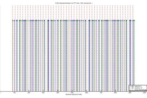
Full Usage of Subcarriers (FUSC)
FUSC subchannelization scheme stands for Full Usage of Subcarriers. In this scheme, all the subcarriers are available for usage. We group the sub-carriers so that there are N groups where N is the number of subsub-carriers we want in a subchannel, i.e. 48. Then, from each group, we pick a subcarrier for each subchannel. See Figure 2.2 for some sample subchannels.
Tile Usage of Subcarriers (TUSC)
Tiles are used in TUSC instead of the clusters in PUSC. More information is given in the standard.
AMC
Subcarriers are distributed to subchannels in adjacent sets.
More information regarding the subcarrier permutation types, with examples, are given in [11].
2.2.1.2 Burst Construction and Burst Profile Selection
Now that we have covered how subchannels are formed from subcarriers, we can go on to explain how these subchannels are allocated to users. The allocation of
0 100 200 300 400 500 600 700 800 900 1000 PUSC−DL Subchannelization for FFT Size: 1024, Symbol No: 1
Subchan 5 Subchan 10 Subchan 30
0 100 200 300 400 500 600 700 800 900 1000 Absolute Subcarrier Index
PUSC−DL Subchannelization for FFT Size: 1024, Symbol No: 2
Subchan 5 Subchan 10 Subchan 30
Figure 2.1: Sample PUSC-DL Subchannel Formations for NF F T = 1024
0 100 200 300 400 500 600 700 800 900 1000 Absolute Subcarrier Index
FUSC Subchannelization for FFT Size: 1024, Symbol No: 1
Subchan 5 Subchan 10 Group Demarkings
Figure 2.2: Sample FUSC Subchannel Formations for NF F T = 1024 – Red dashed
subchannels occurs via supersets of subchannels called bursts. In WirelessMAN-OFDMA, a burst is defined as the region of the total OFDMA frame reserved for a particular user.
For example, if a user is allocated subchannels 10-20 over the OFDM symbols 5-15, that rectangle constitutes the burst allocated for that user. The allocation is not necessarily a single rectangle, but might be a combination of several rect-angles.
A user might transmit more than one burst in a frame, however only one user can transmit at a given burst region. A data region, or a partition are equivalent terms for defining a burst.
The coding and modulation scheme in the burst is constant throughout the burst, and this selection is called the ‘burst profile’. As such, a burst is com-posed of an integer multiple of FEC blocks each coded by the same coder and constellation mapped by the same mapper.
A burst profile in WirelessMAN-OFDMA is determined by two parameters: The choice of Forward Error Correcting (FEC) code, and the choice of constel-lation mapping.
FEC Code Choices Choosing a FEC code requires deciding on three FEC parameters: The type of FEC, the rate of FEC, and the length of the data vector to be encoded.
Types of FEC supported in WirelessMAN-OFDMA compromise convolu-tional coding, which is mandatory, and three other opconvolu-tional FEC types, namely Convolutional Turbo Codes (CTC), Low-density Parity Check Codes (LDPC), and Block Turbo Codes (BTC).
Each of these support various rates and payload lengths, which are given in tables in Appendix B.
Constellation Mapping Choices The choices for constellation mapping are restricted to three, QPSK, 16-QAM and 64-QAM. Of these, QPSK is the mandatory one, and the support for others is optional. All mappings obey the Gray mapping criteria, and the constellation for each are given in Figure 2.2.2.4.
2.2.1.3 Burst Zone
Multiple bursts form a burst zone via stacking the downlink (DL) bursts together and the UL bursts together with Transmit Transition Gap (TTG) and Receive Transition Gap (RTG) in between the stacks. Bursts are combined with the preamble, Downlink MAP (DL-MAP) , frame control header (FCH) and Uplink Map (UL-MAP), the ranging subchannel to make up a burst zone. The subchan-nelization is fixed within a burst zone, similar to the fixation of burst profiles within bursts; and there is a mandatory burst zone using PUSC.
The discussion above applies to TDD frames which we are concerned with in this thesis; also supported in WiMAX 1.0. As the latest 802.16 standard supports FDD operation as well, WiMAX is poised to support FDD systems in the future; however that issue is beyond the scope of this thesis.
2.2.1.4 Data Mapping Through Slots
Once a user is allocated a burst, we already know the subchannels in that burst. Through subchannelization, we also know the subcarriers within each subchan-nel; therefore the set of subcarriers a user is assigned is known. Assume for the moment that the user has full-buffer data, and her data has already been encoded and modulated into (baseband) symbols.
Data mapping at those points occurs through another allocation unit called slots. A slot is defined as a set of subchannels based on the subchannelization scheme. For the mandatory scheme of DL-PUSC, a slot is defined as a subchannel over two OFDM symbols.
Since the slot is defined as the smallest data allocation unit, the data mapping follows this simple rule: Fill the slots one by one, selecting them first by increasing the subchannel index and then by increasing the OFDM symbol index. The catch here is that since a slot itself spans more than one OFDM symbol in the DL-PUSC case, allocation is performed as below:
1. Determine the slot to be filled. It is the left-most slot, i.e. it should have the lowest subchannel index and if there is a tie there, it should have the lowest OFDM index.
2. Fill the first subchannel inside the first OFDM symbol within that slot. Then, continue by filling the subchannel in the next OFDM symbol. 3. Once the slot is filled, proceed to the next slot, starting from step 1.
One final remark that should be made about slots is that since the encoded and modulated blocks will be mapped to the time-frequency matrix slot by slot, a single slot results in low-length blocks. To overcome this, which degrades per-formance, slot concatenation is defined that merges a number of slots according to the MCs selected inside the burst.
For illustration purposes, assume that a user is allocated the first 8 subchan-nels across 22 OFDMA symbols through the DL-PUSC scheme for an FFT size of 1024. A slot is defined as one subchannel over two OFDMA symbols in PUSC. Therefore, the user is assigned a total of 22 ∗ 8/2 = 88 slots. Assume that the MCS chosen is rate-1/2 CTC with QPSK modulation.
The largest encoded and modulated payload length is 432 symbols for this burst profile; so we need at least 432 subcarriers for each FEC block. The maxi-mum allowed concatenation number is 10, therefore, initially, the slot concatena-tion tries to create as many code mappings as possible through concatenaconcatena-tions of 10 slots. Once it creates 7 of such blocks consisting of 10 slots, there are 18 slots remaining, which it uses as 2 blocks of 9 slots. So, the major logic behind the algorithm is create as much as longest possible slots, while at the same time trying to create longer slot configurations from the remaining slots. The exact formulation is given in IEEE 802.16-Rev2[1].
2.2.2
Channel Encoding
Channel encoding comprises the following steps in sequential order: Randomizer, FEC encoding, bit-interleaving and modulation. The input is the raw data from the user, and the output of the procedure is the data to be mapped via the OFDMA allocation.
2.2.2.1 Randomization
This step is restarted for each FEC block. The data is serialized, then XOR’ed with a pseudorandom bit sequence. The pseudorandom bit stream is generated using a seed of [0, 1, 1, 0, 1, 1, 1, 0, 0, 0, 1, 0, 1, 0, 1] and effect of randomization on a sequence of raw data is shown in Figure 2.3.
2.2.2.2 FEC Coding
Four FEC choices are provided, and each choice comes with a set of supported configurations for constellation size and FEC rate. A selection of constellation size and FEC rate constitutes a burst profile selection. Besides the burst profile
0 10 20 30 40 50 60 70 80 90 100 −1 −0.5 0 0.5 1 Index Value
Original Data Stream
0 10 20 30 40 50 60 70 80 90 100 −1 −0.5 0 0.5 1 Index Value
Randomized Data Stream
(+1 mapped to 1, 0 mapped to −1)
selection, another degree of freedom for code construction is the code length. For a given rate and constellation choice, each code provides different code lengths that fit into the concatenated slots explained in previous sections. So, while a burst has a fixed burst profile, even though we know that a code C with a FEC rate R is chosen there along with either QPSK, 16-QAM or 64-QAM, the code length depends on the allocated data region size. Longer code lengths are favored for better performance.
We omit details regarding the encoding and decoding of these well-known codes since they are discussed extensively in the literature. For a brief overview of all the FEC schemes in IEEE 802.16e, [12] presents a concise introduction and a performance comparison of these codes.
In the next subsections, we give information regarding the rates of these FEC options.
2.2.2.2.1 Convolutional Encoding Convolutional encoding is the only
mandatory FEC coding scheme. Set of supported rates is {1/2, 2/3, 3/4} al-though the latter two are obtained via puncturing of codes with rate 1/2.
Gen-erator polynomials for outputs of coding, X and Y are given as G1 = 171OCT
and G2 = 133OCT, of whose graphical interpretation is given in Figure 2.4. A
complete list of supported convolutional code configurations is given in Appendix B.
Convolutional codes are mandatory in WiMAX as well.
2.2.2.2.2 Block Turbo Codes These codes are optional codes and not used
in WiMAX. BTC is a two dimensional code making use as component codes binary extended Hamming codes.
PART 16: AIR INTERFACE FOR BROADBAND WIRELESS ACCESS SYSTEMS P802.16Rev2/D7 October 2008
Copyright © 2008 IEEE. All rights reserved. 1072
This is an unapproved IEEE Standards draft, subject to change.
1 2 3 4 5 6 7 8 9 10 11 12 13 14 15 16 17 18 19 20 21 22 23 24 25 26 27 28 29 30 31 32 33 34 35 36 37 38 39 40 41 42 43 44 45 46 47 48 49 50 51 52 53 54 55 56 57 58 59 60 61 62 63 64 65 8.4.9.2.1 Convolutional coding (CC)
Each FEC block is encoded by the binary convolutional encoder, which shall have native rate of 1/2, a constraint length equal to K = 7, and shall use the following generator polynomials codes to derive its two code bits:
(126)
The generator is depicted in Figure 299.
The puncturing patterns and serialization order that shall be used to realize different code rates are defined in Table 518. In the table, “1” means a transmitted bit and “0” denotes a removed bit, whereas X and Y are in reference to Figure 299.
Table 517—Encoding slot concatenation for different allocations and modulations
Modulation and rate j QPSK-1/2 j = 6 QPSK-3/4 j = 4 16-QAM-1/2 j = 3 16-QAM-3/4 j = 2 64-QAM-1/2 j = 2 64-QAM-2/3 j = 1 64-QAM-3/4 j = 1 G1= 171OCT FOR X G2 =133OCT FOR Y 1 bit
delay 1 bitdelay 1 bitdelay 1 bitdelay 1 bitdelay
Data in 1 bit
delay X output
Y output
Figure 299—Convolutional encoder of rate 1/2
Figure 2.4: Block diagram depicting the encoding process for Convolutional En-coder (courtesy of [1])
2.2.2.2.3 CTCs Convolutional turbo codes are high-performance capacity
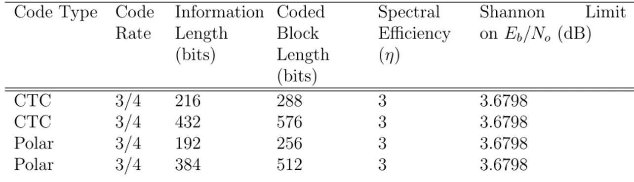
achieving codes. These codes are optional in IEEE 802.16-2009, but are manda-tory in WiMAX. These make use of a slot concatenation rule different from that of convolutional codes, and 8 different burst profiles are supported, namely QPSK with rates {1/2, 3/4}, 16-QAM with rates {1/2, 3/4} and 64-QAM with rates {1/2, 2/3, 3/4, 5/6}. Along with different number of code lengths for each profile, the total number of possible CTC code configuration is 32 and the list is given in the Appendix B.
CTC encoder, with its constituent encoders are given in Figure 2.5. As seen from the figure, there are three paths: The top two paths are for the systematic transaction, i.e. the input is fed to the output intact. In the third path, however, the input first passes through a constituent encoder. The input to this block is determined as a combination of the original channel input paths A and B, through interleaving and switching. Inside this encoder, one can see that the bits fed first are the natural ordered input bits. For the second case of inputs, interleaved bits are used. The outputs are collected to generate subpackets in the
PART 16: AIR INTERFACE FOR BROADBAND WIRELESS ACCESS SYSTEMS P802.16Rev2/D7 October 2008 1077 1 2 3 4 5 6 7 8 9 10 11 12 13 14 15 16 17 18 19 20 21 22 23 24 25 26 27 28 29 30 31 32 33 34 35 36 37 38 39 40 41 42 43 44 45 46 47 48 49 50 51 52 53 54 55 56 57 58 59 60 61 62 63 64 65
— For the W parity bit: 0x9, equivalently 1 + D3
First, the encoder (after initialization by the circulation state Sc1, see 8.4.9.2.3.3) is fed the sequence in the natural order (position 1) with the incremental address i = 0 .. N–1. This first encoding is called C1 encoding. Then the encoder (after initialization by the circulation state Sc2, see 8.4.9.2.3.3) is fed by the interleaved sequence (switch in position 2) with incremental address j = 0, … N–1. This second encoding is called C2 encoding.
The order in which the encoded bit shall be fed into the subpacket generation block (8.4.9.2.3.4) is A, B, Y1, Y2, W1, W2 =
Note that the interleaver (8.4.9.3) shall not be used when using CTC.
The encoding block size shall depend on the number of slots allocated and the modulation specified for the current transmission. Concatenation of a number of slots shall be performed in order to make larger blocks of coding where it is possible, with the limitation of not exceeding the largest supported block size for the applied modulation and coding. Table 525 specifies the concatenation of slots for different allocations and modulations. The concatenation rule shall not be used when using IR HARQ.
For any modulation and FEC rate, given an allocation of n slots, the following parameters are defined:
j is parameter dependent on the modulation and FEC rate
n is floor(number of allocated slots * STC rate/(repetition factor * number of STC layers))
k is floor(n/j) CTC Interleaver 2 1 Constituent encoder A B C1 C2 Y1W1 Y2W2 + S1 + S2 + S3 Parity part Constituent encoder Figure 301—CTC encoder switch Systematic part + + A B A0"A1"! A" N 1– "B0"B1"! B" N 1– "Y1 0" "Y1 1" "! Y" 1 N 1" – "Y2 0" "Y2 1" "! Y" 2 N 1" – W1 0" "W1 1" "! W" 1 N 1" – "W2 0" "W2 1" "! W" 2 N 1" –
Figure 2.5: CTC Encoder Diagram(courtesy of [1])
following order: A, B, Y1, Y2, W1, W2. Interested reader might find detailed
infor-mation about this process in the final version of the IEEE 802.16 standard [1].
2.2.2.2.4 LDPC Similar to CTCs, LDPC codes also achieve capacity
prac-tically.
Rates {1/2, 2/3, 3/4, 5/6} are supported for each constellation choice, so there are 12 different LDPC burst profiles.
Numerous block lengths are supported for each profile, the whole list is given in the Appendix B.
2.2.2.3 Interleaving
After the data is encoded via the FEC, a block is interleaved via a two-stage block permutation. Neighbor subcarriers are separated via the first operation and is independent of modulation.
The second permutation is modulation dependent, and serves in scattering neighboring bits to random parts of the constellation.
At the receiver side, reverse permutations are applied in reverse, in order to retrieve the original sequence.
Since the CTC encoder already has an integral interleaver, interleaver block is not used for configurations using CTC as FEC choices.
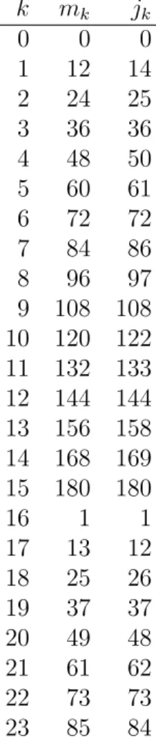
For illustration purposes, observe the transformation of the following encoded
block sequence indices k in second column in Table 2.1. mk refers to the index
of that bit after the first permutation and is defined by the operation:
mk = (Ncbps/d)k mod (d)+ f loor(k/d)k = 0, 1, . . . , Ncbps− 1 d = 16 (2.1)
where Ncpc is the compression gain obtained by modulation mapping and equal
to 2, 4, 6 for QPSK, 16-QAM and 64-QAM respectively and Ncbps is the code
block length input to interleaving process.
Similarly, observe how the second permutation defined by the equation below, interleaves those bits in Table 2.1, where s = Ncpc/2 :
Table 2.1: The Effect of Interleaving Steps on the Index Number for a Code Length of 192 in a 64-QAM Setting
k mk jk 0 0 0 1 12 14 2 24 25 3 36 36 4 48 50 5 60 61 6 72 72 7 84 86 8 96 97 9 108 108 10 120 122 11 132 133 12 144 144 13 156 158 14 168 169 15 180 180 16 1 1 17 13 12 18 25 26 19 37 37 20 49 48 21 61 62 22 73 73 23 85 84
−0.6 −0.4 −0.2 0 0.2 0.4 0.6 −0.6 −0.4 −0.2 0 0.2 0.4 0.6 Quadrature In−Phase QPSK Constellation 1 2 3 4 −1 −0.5 0 0.5 1 −1 −0.8 −0.6 −0.4 −0.2 0 0.2 0.4 0.6 0.8 1 Quadrature In−Phase 16−QAM Constellation 1 2 3 4 5 6 7 8 9 10 11 12 13 14 15 16 −1 −0.5 0 0.5 1 −1 −0.8 −0.6 −0.4 −0.2 0 0.2 0.4 0.6 0.8 1 Quadrature In−Phase 64−QAM Constellation 1 2 3 4 5 6 7 8 9 10 11 12 13 14 15 16 17 18 19 20 21 22 23 24 25 26 27 28 29 30 31 32 33 34 35 36 37 38 39 40 41 42 43 44 45 46 47 48 49 50 51 52 53 54 55 56 57 58 59 60 61 62 63 64
Figure 2.6: Constellations for Different Mappings (Numbers signify the decimal notation of bit sequences, added by 1)
2.2.2.4 Modulation
Constellation mapping using Gray-mapped QPSK, 16-QAM are mandatory while 64-QAM support is optional. The average symbol power is normalized by mul-tiplying the constellation by an appropriate scaling factor.
The figures below show the constellations for QPSK, 16-QAM and 64-QAM. Once the data is constellation mapped, it is further multiplied by a factor of 2 · (1/2 − wk) where wk is a pseudo-random bit sequence defined according to [1,
Section 8.4.9.1.4.1]. Pilot carriers are modulated in a different fashion, boosted 2.5dB compared to the data subcarriers. Interested reader may find further detail in [1, Section 8.4.9.1.4.1].
2.2.3
Multiple Input Multiple Output : MIMO
As channel capacity using single antennas were approached with capacity achiev-ing codes such as LDPC and CTC, improvements in data rate increase needed to be done in a different fashion. The single input single output (SISO) scheme was no longer sufficient. It was shown that the exploitation of multiple antennas at the transmitter and/or receiver side resulted in linear capacity increases with the minimum of the number of transmit and receive antennas [13]. As a result, much of the telecommunications research in the last decade concentrated on Multiple Input Multiple Output (MIMO) concepts, and this technology was immediately applied to real life problems.
WirelessMAN-OFDMA is also one of the newest telecommunications stan-dards of almost all making use newer MIMO technologies. It supports various MIMO schemes, all of them optional. Of particular note is the 2x1 Alamouti scheme [14]. IEEE 802.16m also defines a MIMO 2x2 option which we have implemented in our simulator as well.
For these MIMO schemes, we use the method first proposed by Alamouti in [14]. Two different schemes have been used: 2 by 1, for which there are two transmit antennas and 1 receive antenna; and 2 by 2 for which there are 2 transmit and 2 receive antennas.
Although we did not do simulations with 2x1 MIMO scheme, but only 2x2, it is more appropriate to first introduce this basic case.
![Figure 2.4: Block diagram depicting the encoding process for Convolutional En- En-coder (courtesy of [1])](https://thumb-eu.123doks.com/thumbv2/9libnet/5943182.123822/51.892.237.723.158.421/figure-block-diagram-depicting-encoding-process-convolutional-courtesy.webp)