REVIEW AND ASSESS THE OPTIMAL ARRANGEMENT OF VISCOUS
DAMPERS IN ORDER TO REDUCE THE SEISMIC RESPONSE OF TALL
REINFORCED CONCRETE STRUCTURES
Ashkan VafaeiMsc Students of Structure Faculty of Engineering, Civil Engineering Department, Urmia Branch, Islamic Azad University, Urmia, Iran
Ashkan Khoda Bandeh Lou
Doctor of Philosophy of Technical Sciences, Faculty of Engineering, Civil Engineering Department, Urmia Branch, Islamic Azad University, Urmia, Iran
[email protected] ABSTRACT
In recent years, the call control structures in earthquake using energy dissipating devices such as dampers have been of particular importance. Research has shown that the use of viscous dampers can play an effective role in monitoring the response of structures against the wind, explosion and earthquake. The optimal arrangement is very effective damper efficiency of their performance. In this study, design is ideal viscous damper damping operation for 100 percent and put it in different modes in structures using software ETABS2015 try to determine whether the optimal model can be offered to install dampers in plan and elevation classes, to be answered. The model used in this study is a 20-storey reinforced concrete three-dimensional structure of the records used for non-linear time history analysis of earthquake KOBE and SMART1 and are LANDERS. The results show the effect of the optimal arrangement of viscous damper in reducing the seismic response of structures. However, the optimal location for a viscous damper structure under different earthquake quake because of different characteristics vary. Therefore, it can be a hundred percent for the optimal location pattern presented viscous dampers. LANDERS structures under earthquake model in this study will have the seismic response of the maximum amount of 43.02 percent compared to non-damper. However, in most cases, the best structural response is the time when the dampers in building frames with each other in adjacent springs are installed.
Keywords: Viscous Damper, Seismic Response, ETABS 2015, Time History Analysis, Records. VISCOUS DAMPER
Fluid viscous damper is one of the energy absorbing systems is compared to the physical size of the ability to absorb high energy. So this type of energy dissipation caused by the earthquake dampers can be used in structures. In the past, many applications of fluid viscous dampers to control the vibrations caused by blasting in space systems and defense have been observed. As time has shown that this system can have a significant impact on vibration control. In fact, the production of fluid viscous dampers with high capacity to about 1980 returns. Including its dependence on temperature and frequency characteristics of the damper depending on the severity and frequency of load and load a certain amount of energy wasted
Ron pistons, piston causes a pressure difference on either side of the cap and thus the damping force is generated. Fluid compressibility may cause elastic return force after the piston stroke to prevent this from happening a control valve, the liquid passes through the third compartment provides the Accumulator or storage enclosure.
Viscous damper is analytically dependent on the speed and the force-velocity relationship for viscous damper shown in Equation 1:
Where the damper, the relative velocity of the piston, damping, and speed is an exponential function of speed and function symbols. Damping constant, which is determined by the diameter of the damper and opening areas. Fixed number is between 0.3 to 1.95. Viscous damper behavior is linear with
α
=
1 for the relationship between the damping forces is linear with relative speed. Damper with α < 1 nonlinear behavior is often not useful utility. Damper α > 1 also has a non-linear behavior is extremely effective in minimizing initial shock with relative speed. In this study, linear viscous damper is used. Details viscous damper is shown in Figure 1.Figure 1: viscous damper detail [4]
GENERAL MODEL SPECIFICATIONS
It is a model of building of 20 floors with concrete slab roof. General specifications of the model are as follows:
1. Building is assumed in the city of Urmia. 2 User building is assumed in a residential floors.
3. System X and Y axis for dual-system structures to concrete moment frame with shear walls is considered.
4. Plasticity of concrete moment frame, medium and shear walls are particularly intended.
AGGREGATES SPECIFICATIONS
Due to the lack of steel materials, concrete material properties defined in this research is presented in the table below. α
v
v
C
F
=
.
sgn(
).
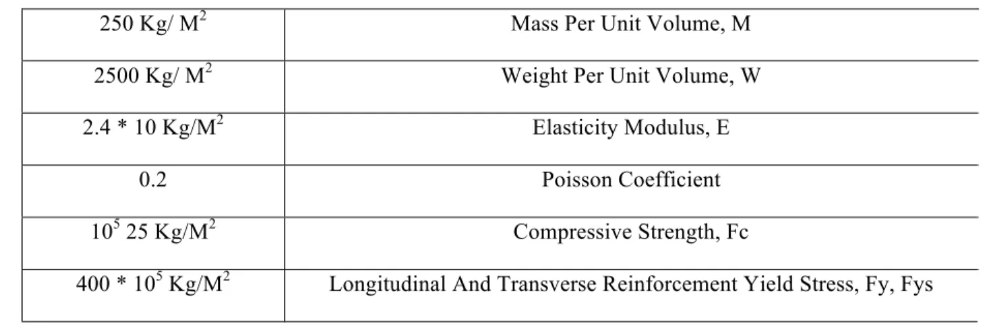
Table 1. Class C25 concrete materials
Mass Per Unit Volume, M 250 Kg/ M2
Weight Per Unit Volume, W 2500 Kg/ M2 Elasticity Modulus, E 2.4 * 10 Kg/M2 Poisson Coefficient 0.2 Compressive Strength, Fc 105 25 Kg/M2
Longitudinal And Transverse Reinforcement Yield Stress, Fy, Fys 400 * 105 Kg/M2
Modulus of elasticity of concrete in accordance with Section IX is calculated as the following equation:
RULES USED
In this study, the following Rules is used to load and building design:
• Gravity and lateral loading on the basis of "national building regulations - Section VI: loads on buildings (2013)"
• Concrete frame design and concrete shear walls based on the "Regulations ACI318-99 and national regulations ninth topic"
• Building Rules Earthquake 2800 (Edition 4)
The use of moment frames with shear walls a very good system for dealing with lateral forces. Since the shear walls, the bulk of lateral forces exerted on the structure and absorb its cut, according to 6-11-8-4 sixth issue, should be 25% of that moment frame alone can withstand earthquakes. Given that the building has a dual system in both directions X and Y, the above paragraph should be considered in the design.
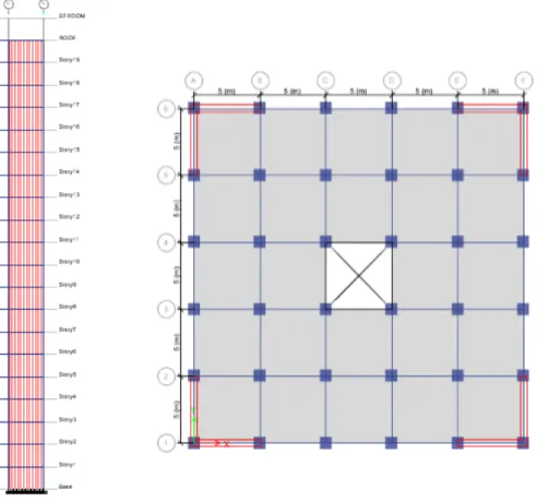
Situations of columns, shear walls, stairs and beam position in class are in the following figure. In this way, positioning is to determine the shear walls in the plan view.
2 9 4
2
.
4
10
/
10
250
15100
15100
f
kg
m
E
=
c=
×
×
=
×
Figure 2: Plan view and shear walls
DETERMINATION OF DAMPING RATIO TARGET AT THE DESIGN LEVEL
According to paragraph A.2.4.113 Rules NEHRP, structures that are supposed to use the damper, absorb the energy induced by the earthquake, should be able to withstand earthquake forces alone 0.75. This means that the reduction in base shear coefficient of the damper (B), the maximum would be 1.35 times the equivalent damping coefficient of 15%. Due to the robust design of structures for comparing arrangement, damping is considered to be the ideal 100%.
Therefore:
1. The initial structure should be cut to 75 percent of Regulation NEHRP to be designed base.
2. Damper system should be designed so that the viscous damping is able to supply 100 percent, this means that your damper damping does the duty ideally.
DETERMINING THE DAMPING COEFFICIENT OF DAMPER:
Structural damping ratio created by the damper (ζ𝑑) is calculated using the following equation. 𝜁𝑑 = 𝑇 Σ𝐶𝑗 𝜑rj2 𝑐𝑜𝑠2𝜃𝑗 / 4𝜋 Σ𝑚𝑖𝜑𝑖2
T in the above period, the main mode of structure, 𝐶𝑗 floor damping coefficient j, φ𝑟𝑗 horizontal displacement of both ends of the damper due to structural deformation in the first mode of deformation, θ𝑗 damper angle with the horizon line on the floor j, 𝑚i seismic mass, class i and φ𝑖 shift class i in the first mode shift is structural deformation. The above relation for linear dampers, and then sung and Konstantino 1 (1994) and Selma and Konstantino 2 (1997) equation for non-linear dampers provided.
The parameter λ is equal to the following formula:
If instead of diagonal layout used in high regard Chevron instead 𝐶𝑜𝑠 θ𝑗 we will be number one.
DETERMINING THE DAMPER ANGLE WITH THE HORIZON
According to the project dampers diagonally (Diagonal) are installed in the structure. Therefore:
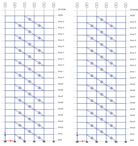
DAMPER MAKE-UP IN STRUCTURE
According to previous research that has been made in the ordering dampers, the most appropriate arrangement on the following consideration:
is assumed to be a damper in each direction 2 and 4 are located between floors. Ie B-C and C-D openings and D-E in frames 2 and 5 in the direction of X and at the mouth of 2-3 V3-4 and 4-5 in frame B and E in the Y damper is located.
8422714
.
0
5
2
.
3
5
2 2=
+
=
θ
Cos
Figure 3: damper arrangement structure CALCULATING THE DAMPING COEFFICIENT OF DAMPER
Calculating the damping coefficient of damper and damper of the classes in each direction 4 in the third floor of a damper are placed in each direction 4:
𝜁𝑑 = 𝑇 Σ𝐶𝑗 𝜑rj2 𝑐𝑜𝑠2𝜃𝑗 / 4𝜋 Σ𝑚𝑖𝜑𝑖2
1=1.876×4×𝐶×0.080878819 / 4𝜋×120616.1387 𝐶 = 2497397.42 𝐾𝑔−𝑠𝑒𝑐/𝑚
DETERMINING THE DAMPER TO MODEL IN ETABS 2015
If pure damping behavior of the damping is concerned, it is necessary to adopt measures to attain the effect of softness spring is removed from the model. For this purpose, it is sufficient to define spring stiffness is big enough.
ω𝑛 = 2π / 𝑇 = 2π / 2.52 = 2.493 τ = 1.1000 ω𝑛 = 0.0004
COMPARING THE ARRANGEMENT AND CONCLUSION
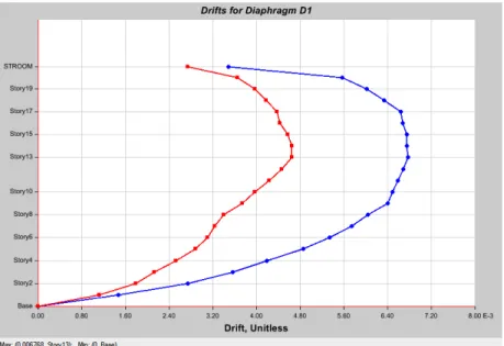
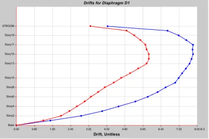
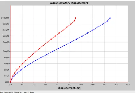
Since the time history analysis in this study for construction of three records KOBE, SMART1, LANDERS use and maximum displacement is LANDERS earthquake. To compare the different modes in the structure of the earthquake LANDERS damper arrangement is used. The results of such displacement classes, classes drift and seismic response of structures for time history, are as follows:
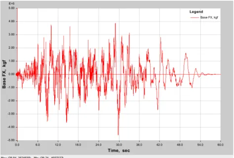
Classes and seismic response of displacement and drift in the first case under LANDERS earthquake will be in accordance with the following forms of graphs where the maximum amounts shown. The maximum displacement 33.871298 cm, the maximum drift 0.006875, maximum seismic responses are 3874830 kg f.
Figure 6: ordering the movement of the oppressed classes Lenders Earthquake in the first arrangement
Figure 8: seismic response of structures under earthquake Lenders in the first case Ordering
2. Shift and drift classes and seismic responses under earthquake LANDERS the latter will be in accordance with the charts following figures in which the maximum values are shown. The maximum displacement cm 37.709797, 0.007809 maximum drift, the maximum seismic responses are 4285287 kg f.
Figure 11: seismic response of structures under earthquake Lenders in the second arrangement
3. Handling and drift classes and seismic response of the earthquake in the third LANDERS will be in accordance with the charts following figures in which the maximum values are shown. The maximum displacement cm 33.871298, 0.006875 maximum drift, the maximum seismic responses are 3874830 kg f.
Figure 14: seismic response of structures under earthquake Lenders in the third Ordering CONCLUSION
According to seeing the results of any of the conditions arrangement, it is specified that the optimal arrangement of the damper to what extent can the results of the seismic response of structures dislocation of classes and drift classes also effective. If ordering the state to reduce the maximum displacement of 30.37%, 39.35% reduction in the maximum drift, reducing the maximum seismic response of 33.28%, 21.75% decline in the second mode setting maximum displacement, 30.03% reduction in the maximum drift, reducing the maximum seismic response of 37% and in the third case ordering the reduction of the maximum displacement of 29.71%, 38.4% reduction in the maximum drift, reducing the maximum seismic response of 43.02% can be achieved. Thus it can be seen that the optimal arrangement of dampers can be achieved with a damper less acceptable results, as seen in the third case the maximum seismic responses is more percent. This arrangement than other arrangement is economically. It also reduced the length and thickness shear wall that also benefits as a result of the economic costs of a project.
REFERENCES
[1] Whittaker, Andrew and Constantinou, M.C. Fluid viscous dampers for building construction. Tokyo Institute of Technology. Tokyo, 133-142, 2000.
[2] Kelly, J.M., Skinner, R.I. and Heine, A.J. Mechanism of energy absorption in special devices for use in earthquake resistant structures, Bull. New Zealand Sec. Earthq. Eng., 5, 63-88; 1972.
[3] Kalaf, D. W., Penn saddle, Joseph. “Structural Dynamics”, Sharif Press, 1998
[4] Dethariya M. K, Shah B. J. Seismic response of building frame with & without viscous damper with using SAP 2000. International Journal of Earth Sciences and Engineering, ISSN 0974-5904, Volume 04, No 06 SPL, pp. 581-585, 2011.
[5] Computers and Structures, Inc. ETABS2000, version 13.0.0 nonlinear, integrated structural analysis and design software. Berkeley, CA; 2013.
![Figure 1: viscous damper detail [4]](https://thumb-eu.123doks.com/thumbv2/9libnet/4416739.75442/2.918.261.667.491.682/figure-viscous-damper-detail.webp)