IOP Conference Series: Materials Science and Engineering
PAPER • OPEN ACCESS
On the general requirements for design of earthquake resistant buildings
in the Turkish Building Seismic code of 2018
To cite this article: K Güler and Z Celep 2020 IOP Conf. Ser.: Mater. Sci. Eng. 737 012015
Content from this work may be used under the terms of theCreative Commons Attribution 3.0 licence. Any further distribution of this work must maintain attribution to the author(s) and the title of the work, journal citation and DOI.
Published under licence by IOP Publishing Ltd
BCEE4
IOP Conf. Series: Materials Science and Engineering 737 (2020) 012015
IOP Publishing doi:10.1088/1757-899X/737/1/012015
1
On the general requirements for design of earthquake resistant
buildings in the Turkish Building Seismic code of 2018
K Güler1 and Z Celep2
1 Department of Civil Engineering, Faculty of Civil Engineering, Istanbul Technical
University, 34469 Maslak, Istanbul, TR
2 Department of Civil Engineering, Faculty of Engineering, Fatih Sultan Mehmet Vakıf
University, 34445 Sütlüce, Istanbul, TR
Abstract. Turkish Building Seismic Code has been revised after eleven years once more and its application is compulsory since the beginning of 2019. The new code is published together with a new Earthquake Hazard Map and it consists of 17 chapters. Some of the chapters have been revised thoroughly updated, whereas some new chapters are added as well. In the revision of the code, developments in the earthquake engineering and in the building technology are taken into consideration. Requirements related to ground motion are given in a separate chapter by defining four levels of earthquake motion. The code contains the strength design of the buildings as it is accustomed in the previous codes. However, performance based design is highlighted for high-rise buildings and for socially important buildings located moderate and high seismicity regions. The code has new separate chapters for high-rise buildings, cold-formed steel buildings, timber buildings and seismically isolated buildings. Furthermore, it has a new chapter for non-structural elements as well. The chapters involving design of steel structures, seismic evaluation of the existing buildings, and structural and geotechnical design of foundations are revised significantly. The chapter on the design of reinforced concrete contains a limited modification as well. However, since most of the buildings are reinforced concrete, this chapter relatively is important. In the present paper, the general design and evaluation approach of the code presented in detail and comparatively by considering the previous Turkish Building Seismic Codes.
1. Introduction
Turkey is located in an earthquake prone region in the world; therefore, it is important that buildings should be constructed by considering the gravity loads as well as the seismic loads. For the reinforced concrete buildings there are two Turkish codes. The first one is TS500, Requirements for Design and Construction of Reinforced Concrete Structures, and second one Turkish Building Seismic Code, which gives additional requirements for buildings to be constructed in seismic zones. In fact, the first version of the seismic code was published in 1940. Since then, several versions of the code have been published always adopting stricter requirements for the structural elements and for the seismic load. The last version of the seismic code of 2018 has come into force since the beginning of 2019. The new version of the code consisting of 17 chapters is developed by revising and expanding the old chapters of the code from 2007 and by adding new chapters to reflect the new development in earthquake
BCEE4
IOP Conf. Series: Materials Science and Engineering 737 (2020) 012015
IOP Publishing doi:10.1088/1757-899X/737/1/012015 engineering and in construction methods. The present paper attempts to give an overview of the general requirements of the code.
The code covers only RC buildings, and does not cover other type of structures, such as, historical structures, coastal and port structures. The code has two types of supplements; supplementary annexes for a better understanding and implementation of the relevant parts of the code and includes non-mandatory requirements. These non-mandatory annexes, which are an integral part of the code, contain mandatory requirements.
The most important modification and advances introduced through the new version of the code can be stated as follows:
a. Inclusion of a new extensive chapter on seismic effects by defining acceleration spectra for the horizontal motions and definition of a spectrum for the vertical motions, similar to those given in ASCE-07,
b. Inclusion of earthquakes in four levels, such as DD-1, DD-2, DD-3 and DD-4, the first two may correspond to MCE and design earthquakes in ASCE-07,
c. Inclusion of multi performance states for socially important buildings and all high-rise buildings, d. Inclusion of design ultimate soil pressures and use of the factored loads in foundation design, e. Inclusion of separates sections for non-structural elements, high-rise buildings, seismically isolated
buildings, light weight steel structures,
f. Inclusion of nonlinear deformation based analysis, design and evaluation methods for socially important,
g. Inclusion of the overstrength factor and detailed use of the capacity design,
h. Inclusion of displacement limits depending on the connection between the partition walls and structural elements,
2. Seismicity
Turkish Earthquake Risk Maps are developed as a result of separate project and they are published at the same time as the code by adopting probabilistic definition of the seismic risk. In the maps, horizontal and vertical spectral parameters are given for four different levels of earthquake. In the previous code four earthquake zones and a fifth zone without seismic risk had been defined. However, the new maps assume the whole country having seismic risk and give the related the parameters
depending on the geographical position. As it is in ASCE-07, the risk maps provide the parameters S S
(for short period) and S (for the 1.0s period) for 5% damping ratio.1
Seismic risk is defined probabilistic way due to its uncertainty depending on the geographic location, which evaluated by considering the following parameters.
a. Geographic location-dependent parameters: the tectonic structure of the region, active faults and fault mechanisms (Active Fault Map of Turkey, MTA-2012)
b. Earthquakes and their properties in the region (Earthquake Catalogs),
c. Soil conditions between the source and the region considered (Decay Relations of Seismic Parameters, Earthquake Motion Estimation Equations).
Seismic risk is defined probabilistic way due to its uncertainty depending on the geographic location w
Spectral response acceleration parameters SSDS FS S and S1D S F1 1 are obtained by considering the site soil class defined as ZA, ZB, ZC, ZD, ZE and ZF The parameters F and S F which depend on soil 1
properties to be determined by geotechnical investigation of the top layer of 30m . The standard soil having a shear wave velocity of 760m s/ lays in between the soil classes ZB and ZC. The local soil
BCEE4
IOP Conf. Series: Materials Science and Engineering 737 (2020) 012015
IOP Publishing doi:10.1088/1757-899X/737/1/012015
3
parameters F and S F are greater than unity to increase the spectral parameters for the soils ZC-ZF, 1
whereas they are less than unity to decrease them for ZA and ZB.
The seismicity parameters are given for the four seismic levels, as follows:
a. DD-1: A earthquake with 2 percent probability of exceedance within a 50-year period having a return period of 2475 years, very rare earthquake, the maximum credible earthquake, the largest earthquake considered)
b. DD-2: A earthquake with 10 percent probability of exceedance within a 50-year period having a return period of 475 years, rare earthquake, standard design earthquake)
c. DD-3: A earthquake with 50 percent probability of exceedance within a 50-year period having a return period of 72 years, frequent earthquake)
d. DD-4: A earthquake with 68 percent probability of exceedance within a 50-year period having a return period of 43 years, service earthquake, very frequent earthquake)
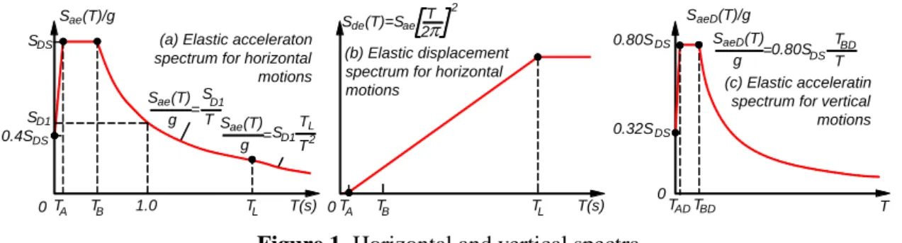
In addition to the horizontal seismic motions, the code defines vertical seismic motion as well. Typical design spectra for horizontal and vertical seismic motion are given in Figure 1.
Spectral parameters are given in the Earthquake Risk Maps depending on the geographical location. These spectral parameters are modified by considering the local ground soil conditions. Design Acceleration Spectrum is obtained using these parameters. The maximum earthquake loads, the maximum displacement and the maximum internal forces are obtained by using these spectral curves.
0 (a) Elastic acceleraton
spectrum for horizontal motions
(b) Elastic displacement spectrum for horizontal
motions (c) Elastic acceleratin
spectrum for vertical motions L T T2 0.4SDS 0 0 g = S (T) ae g = S (T)aeD g =0.80SDS T T BD TA TB 1.0 TL T(s) SD1 S (T)ae SDS S (T)/gae TA TB TL S (T)=Sde ae T(s) T 2 2 D1 S T SD1 S (T)/gaeD 0.80SDS 0.32SDS TADTBD T
Figure 1. Horizontal and vertical spectra
Seismic acceleration records to be used in the time domain analyses have to be compatible with the Design Acceleration Spectrum. Appropriate acceleration records must be selected accordingly, scaled and modified for this operation. In the selection of acceleration records the following properties have to be taken into consideration:
a. Fault distances, source mechanisms and local ground conditions,
b. Past earthquake records,
c. Number of acceleration sets must be at least eleven.
Furthermore, in scaling and modifying of the acceleration records to be used, the followings should be observed:
a. Amplitudes of the average of the selected acceleration records between 0.2T and 1.5T periods are
scaled so that they are not smaller than the design acceleration spectrum, where T is the
fundamental period of the building,
b. In the three-dimensional analysis, the square root of the sum of the squares of the spectra of the two
horizontal components of each selected seismic record set is not to be less than 1.3 those of the
design spectrum in between periods 0.2T and 1.5T to the amplitudes of the design acceleration
BCEE4
IOP Conf. Series: Materials Science and Engineering 737 (2020) 012015
IOP Publishing doi:10.1088/1757-899X/737/1/012015
In addition to the horizontal seismic motions, the code defines vertical seismic motion as well. Typical design spectra for horizontal and vertical seismic motion are given in Figure 1.
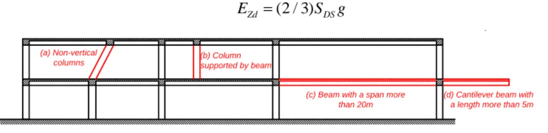
Vertical seismic effect: In buildings having DTS = 1, 1a, 2, 2a and the following elements, the code
requires analysis and design of those elements only by using the Modal Superposition Method using the vertical elastic acceleration spectrum. In the calculation of the vertical seismic effect in the vertical structural elements, R I/ 1 and D1 are taken. The cases which require vertical spectral analysis can be given as follows (Figure 3):
Buildings with non-vertical columns.
Buildings with columns supported by beams,
Buildings having beams with a span of 20m or more,
Buildings having horizontal cantilevers with a cantilever length of 5m or more,
In the parts of the structural system other than the above mentioned elements and in buildings which do not have these elements, vertical earthquake effect can be considered similar to the vertical loading as follows:
(2 / 3)
Zd DS
E S g (1)
(c) Beam with a span more than 20m
(d) Cantilever beam with a length more than 5m (a) Non-vertical
columns (b) Columnsupported by beam
Figure 2. The cases which require vertical spectral analysis 3. General requirements for analysis and evaluation
The code includes some new concepts in additions to those of its previous version. These concepts are briefly summarized below.
3.1. Building-Use Classes (BUC) and Building Importance Factor (I)
They are defined depending on the use of the building. Buildings that need to be used after earthquake, buildings which are used in long term by large number of people and buildings where valuable or dangerous goods are stored are named as BUC=1 and assigned a building importance factor of I=1.5. Buildings that is used by large number of people in a short period of time (BUC=2) has an important factor of I=1.2, whereas I=1 for the remaining buildings (BUC=2).
3.2. Seismic Design Class (SDC)
It is defined depending on the Short Period Design Spectral Acceleration Coefficient SDS of DD-2 earthquake ground motion and on the Building Use Class. They are given as 1a-4a and 1-4. The alphabetical index indicates a high importance. The digital index is related to the seismicity being 4 is the lowest. For example, the earthquake design class of a school building is 1a in an area where the earthquake effect is high (SDS 0.75), whereas that of a residential building in the region where the earthquake effect is low (SDS 0.33) is 4.
3.3. Building Height Class (BHC)
Eight Building Height Classes (BHC) are defined depending on the Seismic Design Class to define the permissible height limits for building structural systems, where buildings with BHC=1 corresponds to the high-rise buildings and their design and evaluation requirements are given in Section 13 of the code separately.
BCEE4
IOP Conf. Series: Materials Science and Engineering 737 (2020) 012015
IOP Publishing doi:10.1088/1757-899X/737/1/012015
5
3.4. Structural systems of buildings
Almost all types of structural systems are defined separately in the code for reinforced concrete, steel and masonry buildings in a long table. The table includes also, precast, timber, light-weight steel, seismically isolated structures. For each type of buildings, several variety of structural system is defined, including high and limited ductility system as well. For the reinforced concrete buildings the following structural system types can be found, such as, frames, shear walls connected to each other by with and without coupling beams and their combinations. In this table Overstrength Factor, permitted Building Height Class and Structural Behavior Factor which is closely related to Earthquake Load Reduction Factor are given for each structural system. As expected, the last factor depends on the ductility of the structural system, which comprises the ductility of the structural elements and that of the cross sections.
3.5. Building performance level
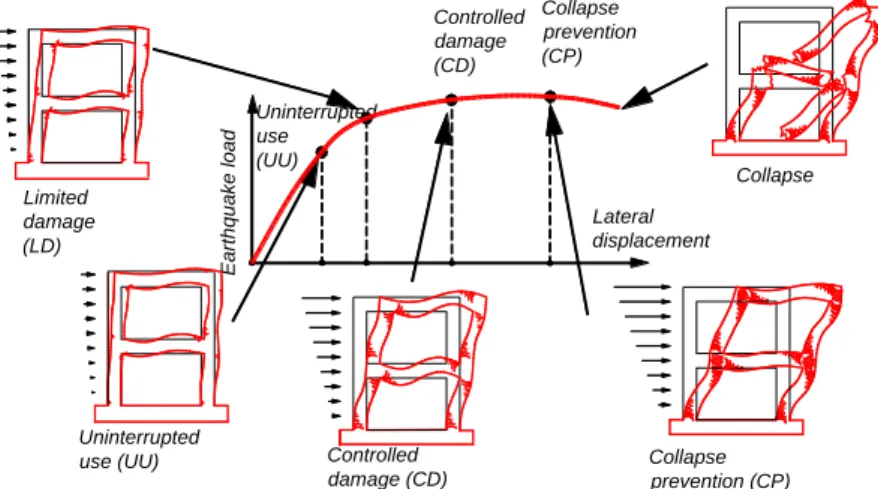
Based on the level of the structural damage level, the following four Building Performance Levels are defined (Figure 3):
Uninterrupted Use (UU) Performance Level corresponds to a state where structural damage does not occur in the building structural system or the damage is negligible,
Limited Damage (LD) Performance Level corresponds to a state where only very limited damage (~ nonlinear behavior) occurs in the building structural system.
Controlled Damage (CD) Performance Level corresponds to a state where damage in the structural system is in a level that the structural system can be economically strengthened.
Collapse Prevention (CP): Performance Level is a state just before collapse of the building structural system.
3.6. Building design approaches
The code defines the following two design and evaluation approaches:
Strength Based Design and Evaluation is accomplished by ensuring that the strength capacity (force and moment) in the section is equal to or greater than the strength demand of the section,
Deformation Based Design and Evaluation is achieved by ensuring that the deformation capacity in the section (unit elongation and shortening of concrete and steel and plastic rotation of the plastic hinges) is equal to or greater than those of the deformation demand.
The deformation based design is preferred in the cases of the large seismicity to grasp the nonlinear behavior of the structural system and that of the socially important buildings for increasing approximation level of the analysis.
Limited damage (LD)
Uninterrupted
use (UU) Controlled
damage (CD) Collapse prevention (CP) E arth quak e lo ad Controlled damage (CD) Collapse prevention (CP) Lateral displacement Collapse Uninterrupted use (UU)
BCEE4
IOP Conf. Series: Materials Science and Engineering 737 (2020) 012015
IOP Publishing doi:10.1088/1757-899X/737/1/012015 3.7. Target performance levels
The code defines specific target levels to be satisfied, earthquake levels to be considered and design and evaluation approach to be implemented for various building types to be designed and evaluated, such as, reinforced concrete, precast, steel and seismically isolated buildings. For buildings in regions with large seismicity and socially important buildings multiple target performance levels are required, whereas for buildings having lower height and an importance factor being I=1, only one target performance level is found to be satisfactorily, such as, Controlled Damage Performance Level to be checked by using the Strength Based Design under DD-2 Earthquake. On the other hand, for high-rise buildings the code requires very detailed analysis and design steps, checking all damage states under in various earthquake levels by using design and deformation based approaches.
3.8. Capacity design principle
To archive ductile behavior and to prevent brittle behavior, in the case of increased earthquake effects, the capacity design principle is used by increasing the failure capacity that produces brittle behavior than that produces ductile behavior. This process is called Capacity Design Principle. The code imposes use of the capacity design together with the strength based design. One of the examples of the capacity design is that the design shearing force in beams and columns is obtained by considering the ultimate bending capacities by taking into account strain hardening of reinforcement of the end sections.
3.9. Equal displacement rule
This rule is widely used in the earthquake engineering often without distinctly referring to it. The maximum displacement of a linear elastic system subjected to a seismic loading is very close to that of the system having nonlinear inelastic behavior. This property is often stated as Equal Displacement Rule. This rule is can be assessed only numerically, and it should be noted that this rule applies on the result as an average. On the other hand, for the rigid systems the maximum displacement of the nonlinear system appears to larger than that of the linear system. The reflection of this rule can be found in the code in calculation of displacements, where seismic displacements are obtained as a result of linear analysis by considering the elastic seismic loads. Another application can be found in determining of the performance points of the structural system in the process of the nonlinear evaluation process.
3.10. Overstrength Factor D
Overstrength factor D is one of the new parameters introduced in the code. It is defined as the ratio of yield strength to design strength D fy / fd. Overstrength factor represents the ratio of actual strength and the design strength which results in the difference of the stresses. For example the stresses in concrete and steel can be written as fck fcd and fsu fyk fyd. Additionally, overstrength factor increases in the structural elements when the minimum reinforcement ratio is effective. Generally, this factor lays in between 2.0~3.0. In the capacity design, brittle capacity is kept larger than the ductile failure to prevent the brittle failure. Therefore, it is important that the yield strength is obtained sufficiently accurate, where overstrength becomes significant. In the application of the overstrength factor the following points deserves attentions:
a. In evaluations of design internal forces which yield a ductile failure of the high and limited ductility structural elements (such as, failure due to bending and due to tensile force in concrete structural elements), an increase due to overstrength factor is not required, i.e., D1.
b. In evaluations of internal forces which yield a brittle failure of the high and limited ductility structural elements (such as, failure due to shear force in concrete buildings and in connections in steel buildings), an increase by the overstrength factor is required, i.e., D1. However, the increased internal forces cannot be greater than those resulting from the capacity design.
c. In calculation of plane stresses in slab obtained by using reduced earthquake loads have to be increased by the overstrength factor.
BCEE4
IOP Conf. Series: Materials Science and Engineering 737 (2020) 012015
IOP Publishing doi:10.1088/1757-899X/737/1/012015
7
d. Reduced in-plane forces in building floors will be increased by the overstrength factor.
e. In buildings having basements surrounded by rigid basement walls, internal forces in the structural elements and forces transferred to the foundations, an increase due to overstrength factor is required, i.e., D1.
3.11. Yield strength and ductility
Pushover curves in two directions comprise a type of the backbone of the load-displacement and in the repetitive loading and this curve can be derived from the loading experiment as well as from the numerical analysis by considering inelastic deformations. As it is seen, the seismic loading in a structural system is limited by its capacity not by the extent of the seismic effect (Figure 4). When the seismic effects increases, the inelastic deformation increases only. The limits of the inelastic deformations govern by the ductility capacity and by the second order effects.
3.12. Earthquake Load Reduction Factor R T a( )
Elastic seismic loads are determined by using well known principles of the structural dynamics. These loads are reduced by employing Seismic Load Reduction Factor which depends on the ductility of the structural system (Figure 4). Generally, this factor depends on the performance level considered and on the extent of the inelastic deformations. When inelastic deformations large and extensive, larger reduction factor is expected. However, the code specifies Structural System Behavior Factor depending on the type of the structural system which equal to the Seismic Load Reduction Factor except for very low load period of the structures. When the period of the structural system is very low, it is expected that extend of the inelastic deformations will be very limited, so is the seismic load reduction factor. For very low periods, reduction factor approaches to the Overstrength Factor.
Ts Ts
R = Earthquake load reduction factor R = Structural system bahavior factor D = Overstrength factor
= Building importance factor
a
I R = Yield strength reduction factor
= Ductilityy (b) (a) R/ R TB 0 D T a R TB 0 1 T y I
Figure 4. Yield strength reduction factor and earthquake load reduction factor 4. Structural irregularities
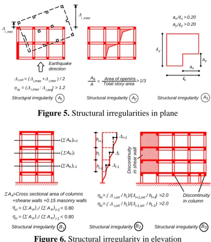
They are defined in plane and in elevation. The code defines structural irregularities in the horizontal plane and in the elevation and encourages eliminating irregularities as much as possible (Figure 6 and 7). However, when it is unavoidable, while some of the structural irregularities cause punishments, such as, by increasing the earthquake effect and by requiring more detailed analysis, only very limited number of structural irregularity is banned, such discontinuity of shear walls in lower stories or discontinuity of a column by supporting it to cantilever beam. The planar irregularities can be stated as torsional irregularity, openings in slabs and planar shape irregularity, whereas the irregularities in elevation are strength and stiffness irregularities and discontinuity of columns and shear walls.
The code points to the significance of the structural system and the architectural configuration of the building and stresses to the following points distinctly.
Simplicity of structural system enables designer to use less assumptions for modeling and for analysis, to predict its response under vertical and seismic loadings and to check results relatively easily.
Predictable and assessable structural behavior can be attained, when structural system has symmetry and regularity with respect to mass, stiffness and strength. Analysis of irregular structures requires large number of assumptions. Uncertainties in behavior material and earthquake loading affect results negatively.
BCEE4
IOP Conf. Series: Materials Science and Engineering 737 (2020) 012015
IOP Publishing doi:10.1088/1757-899X/737/1/012015
High level of redundancy enables the structural system to resist to the external loads even if a few elements fail. Generally, the higher the static degree of indeterminacy of the system is, the larger the level of the redundancy. One other property is the load path which is closely related to redundancy as well. It is expected that more than one continuous load path should be provided, so that if one of the load path fails, the other should be used to transfer the vertical and seismic loads from the point where is originated down to the foundation. Along the load paths, connections and elements having adequate strength and deformation capacity should be provided.
3
A Structural irregularity1 A2
1/3
>
Total story area Area of openins i,min i,max = (+i,ort ) / 2 > 0.20 /y ay 0.20 > x l / x a y a x a x l y l i ,max = (bi i,avg) > 1.2 A A b = Earthquake direction i ,min l i,max 1
A Structural irregularity Structural irregularity
Figure 5. Structural irregularities in plane
( A )e i+1 i ( A )e B3 2 B = ki i,ort i+1,ort >2.0 i-1 i i-1 ( A )e i+1 Discontinuity in column 1 B = ci ( )Aei/( )Aei+1< 0.80
+shearw walls +0.15 masonry walls =Cross sectional area of columns Ae = ci ( )Aei/( )Aei-1< 0.80 h h h i+1 i i-1 / h )/(i / h )i+1 =
ki i,ort/ h )/(i i-1,ort/ h )i-1 >2.0
Structural irregularity Structural irregularity Structural irregularity
D isc ontinuity in sh ear wa ll
Figure 6. Structural irregularity in elevation 5. Strength-based design
Strength-based design starts with a linear earthquake analysis of the structural system under reduced earthquake loads. Earthquake internal forces are increased with Overstrength Factor, when they correspond to a brittle failure mode and combined with internal forces due to the gravity load to obtain the corresponding Strength Demand. Finally, cross sections and structural elements is designed that their capacity is equal or higher than the corresponding demand. In the final step drift ratio is checked. The design process is repeated by updating the cross sections and the structural configuration until acceptable results are found.
6. Structural systems
The code defines three structural systems depending on ductility levels:
a. Structural systems having high ductility b. Structural systems having limited ductility c. Structural systems having mixed systems
Structural systems with high ductility have higher structural behavior factor, i.e., higher earthquake load reduction factor and lower design earthquake load, however they satisfy additional rules as
BCEE4
IOP Conf. Series: Materials Science and Engineering 737 (2020) 012015
IOP Publishing doi:10.1088/1757-899X/737/1/012015
9
application of the capacity design and as reinforcement detailing. Structural systems having limited ductility satisfies less strict rules, whereas their design earthquake loads are high. On the other hand, structural systems of mixed type are a combination of frames having limited ductility and shear walls having high ductility and steel diagonal frames.
The code gives the maximum height limits for each type of the structural system depending on the seismic Design Class, which depends on the seismicity of the area and on the building-use class. Furthermore, the structural behavior factor and the overstrength factor is also given depending on the structural system. The code gives R I/ 2.5 and D1.5 for the basement floors by considering that their high stiffness and low ductility.
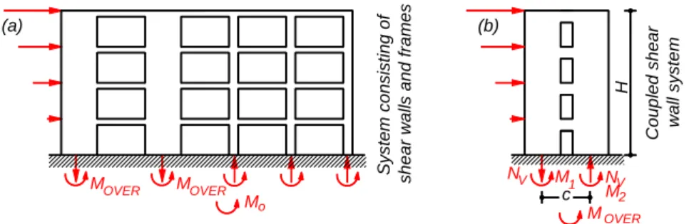
M c 2 MOVER H M M NV M1 NV Sys tem co ns is ting of sh ea r wal ls and frames C oup led shear w all s ystem OVER o MOVER (b) (a)
Figure 7. a) Shear walls and frames system and b) Coupled shear wall system
The code gives some specific conditions related to the structural systems consisting of a combination of frames and shear walls as follows:
a. A system can be regarded a combination of high ductility frames and high ductility shear walls (or steel diagonal frames), when the ratio of the sum of the overturning moments of the shear walls
OVER
M
to the seismic total base moment M satisfies (Figure 7a): o
0.40MOVER /Mo0.75 (2) which maintained a reasonable balance between frames and shear walls. The relation ensures that the contribution of the frame system to the overturning moment is not smaller than 25%, because the frame system has large ductility and redundancy. On the other hand, this relation also ensures that the contribution of the shear walls is smaller than 40%, because the shear walls have very high lateral load capacity and lateral stiffness.
b. A system can be regarded a mixed structural systems, i,e., a combination of limited ductility frames and high ductility shear walls (or steel diagonal frames), when the ratio of the sum of the overturning moments of shear walls MOVER to the seismic total base moment M satisfies o
(Figure 7a):
/ 0.25
OVER o
M M
(3)
This relation ensures that the contribution of the high ductility shear walls is smaller than 25%, because the shear walls have very high lateral load capacity and lateral stiffness. They have significant ductility, because they designed accordingly.
Coupled concrete shear walls:
Behavior of the coupled concrete shear walls are in between frames and shear walls, depending on their opening and their coupled beams. They are formed by connecting the two-part shear walls connected with short beams having very high shear strength. Two shear walls connected to each other
BCEE4
IOP Conf. Series: Materials Science and Engineering 737 (2020) 012015
IOP Publishing doi:10.1088/1757-899X/737/1/012015
by beams can be regarded as a coupled concrete shear wall provided that following relation is satisfied: 1 2 1 / 3 V V OVER V c N c N M M M c N (4)
where MOVER is the overturning moment and is the connectivity coefficient, which represents the frame effect (Figure 7b). This condition ensures that the frame effect is significant. However, when the connectivity coefficients high and close to unity, then the connecting beams will excessively be enforced. For this reason the code recommends that the connectivity coefficient satisfies 2 / 3.
Factor for the effective section rigidity:
The code requires that the effective section stiffnesses are used in the analysis of reinforced concrete buildings to consider cracking of concrete and nonlinear deformations of concrete and steel. A global reduction factor is defined for each structural element to be applied to the gross section rigidities, such as normal force and bending moment rigidities. As seen, when the bending moment is effective, the reduction is small, whereas the reduction is less effective when the normal force is effective.
7. Concluding remarks
In the present paper, the main principles of the new Turkish Building Seismic Code are discussed. The code has been prepared as detailed as possible. However, due to the variety of buildings in practice, there will certainly be some issues to be interpreted. Simplicity of the code is important for its conscious implementation by the practicing engineers. In the construction of earthquake resistant buildings, it is important to prepare the projects in accordance with the code and also important to make the construction in accordance with the project as much as the code. The Turkish seismic code has been brought to the highest level possible in terms of earthquake engineering. For its conscious implementation by the practicing engineers, professional training with the contribution of official institutions, universities and chamber of civil engineers is of vital importance. However, it is worth to note that the most important step in our country is on-site implementation of the project and the steps to be taken in this regard will ensure that the issue is carried to the upper level.
References
[1] Celep Z 2018 Introduction into Earthquake Engineering and Earthquake Resistant Design, (Istanbul: Beta Publications)
[2] Turkish Building Seismic Code 2018, Prime Ministry, Disaster and Emergency Management Presidency (AFAD), Ankara, 2018.
[3] Specification for Buildings to be Built in Seismic Zones (2007), Ministry of Public Works and Settlement, Ankara, 2007.
[4] ACI Building Code Requirements for Structural Concrete 2014, American Concrete Institute. [5] TS500 Requirements for Design and Construction of Reinforced Concrete Structures 2000,
Turkish Standard Institute.
[6] Explanatory Examples for Turkish Seismic Code 2018, Chamber of Civil Engineers, İstanbul. [7] ASCE-07, Minimum Design Loads for Buildings and Other Structures, ASCE, 2010.