Computerized Control of the Procedure for Detecting
and Removing Airborne Particles in Operating Rooms
¨
Omer Faruk Bay1,3and Nesip Erg ¨ul2
Surgical-site infections are still a major problem in modern medicine. Normal skin flora of patients or healthcare workers causes more than half of all infections following clean surgery, but the importance of airborne particles in this setting remains controversial. The use of ultraclean air in operating rooms has been shown to reduce infection rates significantly. High efficiency particulate air (HEPA) filters are used in some modern operating rooms. Although the uses of HEPA filters, the air quality should be controlled by another device to make safe the air in operating rooms and intensive care units. In this study, a computerized system was established to control the cleanliness of the air by measuring the presence of airborne particles of varying sizes and numbers in operating rooms. When the maximum values are exceeded, the system warns the authorized people by phone, sound, or displays.
KEY WORDS: airborne particles; dust measurement; operating rooms; clean-room technology.
INTRODUCTION
Atmospheric pollution is still one of the most pressing problems. This pollution has reached a level that poses a potential threat to the health and well-being of population.(1,2)The indoor environment can potentially place human occupants at greater risk than outside environment, because enclosed places can confine aerosols and allow to build up to infectious doses. Surgical-site infections are the leading complication of surgery.(3)To reduce infections, it should be emphasized on air quality and its control in operating rooms. Several studies have shown a reduced number of infections when a surgery is performed in operating rooms with ultraclean air facilities.(4–7) This can be achieved by well designed and controlled ventilation of operating rooms.
Conventional plenum ventilation with filtered air is used to remove airborne particles≥5 µm in most modern operating rooms. Few modern operating rooms
1Department of Electronics and Computer Education, Faculty of Technical Education, Gazi University,
Teknikokullar, Ankara, Turkey.
2Sosyal Bilimler M.Y.O. Selcuk University, Konya, Turkey.
3To whom correspondence should be addressed; e-mail: [email protected].
117
have HEPA filters that remove airborne particles of 0.3µm and above.(3,6)With the use of HEPA filters in operating room ventilation, there is a tendency to apply clean-room technology standards used in industry for hospitals. Most of the industrialized countries have set their own standards. These standards are based on measuring the presence of particles of varying sizes and numbers.
Although the uses of HEPA filters, the air quality should be controlled and monitored by another device to make safe the air in operating rooms and intensive care units. In this study, a computerized system was established to control the clean-liness of the air by measuring the presence of airborne particles of varying sizes and numbers in operating rooms. When the threshold values are exceeded, the system warns the authorized people by phone, sound, or displays. The system consists of a personnel computer, an instrument used in volumetric air sampling, and a multiple environment selector.
MATERIALS AND METHODS
Configuration of the System
The main purpose of this study is to ensure that the particle measurement de-vice measuring the dust particles in operating rooms is controlled with the help of the computer. The proposed system consists of a personnel computer and a dust measurement device. The device and the computer are located in the most appropri-ate place of the hospital sporting the relappropri-ated operating rooms. The communication between the computer and the dust measurement device is performed using the par-allel port of the computer (LPT). Tubes (air channel) are installed to vacuum and transfer the air in the operating rooms through the dust measurement device. It must be ensured that these tubes are installed on either the ceilings or the side walls of the operating rooms.
As also seen in the layout plan of the system, shown in Fig. 1, the computer and the dust measurement device are positioned in a central room located near
the operating rooms. A tube connected to the dust measurement device is installed in the operating rooms in order to ensure that the dust in the environment is mea-sured. The mechanism, ensures this air transmission line, is installed either separately for each room, or it will be arranged as interconnected through one main tube. In this study, the second method of installation is selected. The flap of the air tube of the operating room to be monitored is opened, and the flaps for other rooms are closed.
When selection of an operating room to be monitored, related flap is opened and the other flaps are closed by the computer. It will be also necessary to determine a stand-by time for making correct air sampling. This stand-by time will be different for each operating room. During the stand-by time, the system let the air coming through the tube thrown away. After completion of this process, measurement of airborne particles is started to evaluate the air in the related operating room. A multiple environment selector is used for performing the opening and closing process of the flaps.
Operation of the System
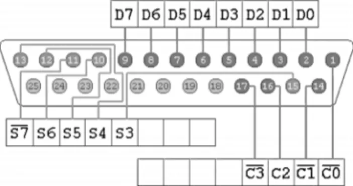
The parallel port (LPT) of the computer has been used for connecting the dust measurement device to the computer. Virtually every PC has a parallel port that serves as a printer interface. But the LPT can be used for much more than this, in-cluding interfacing to control circuits, data-acquisition devices, and instrumentation. The original IBM-PC’s Parallel Printer Port, shown in Fig. 2, had a total of 12 dig-ital outputs and five digdig-ital inputs accessed via three consecutive 8-bit ports in the processor’s Input/Output (I/O) space.
• Eight output pins accessed via the DATA Port,
• Five input pins (one inverted) accessed via the STATUS Port, • Four output pins (three inverted) accessed via the CONTROL Port, • The remaining eight pins are grounded.
LPT pin numbers, the function of each pin, and the direction of data are given in Table I.
To make communication between the computer and the multiple environments selector, we can use the 378H, or 278H I/O address which are the data sending
Fig. 2. Parallel port connector of the personnel computer.
Table I. Parallel Port Pin Numbers and Corresponding Functions
Pin no. Function Input/output Pin no. Function Input/output 1 Data strobe Input/output 10a Data acknowledge Input
2 Data bit 0 Output 11 Busy Input
3 Data bit 1 Output 12 Out of paper Input
4 Data bit 2 Output 13 Selected Input
5 Data bit 3 Output 14 Auto line feed Input/output 6 Data bit 4 Output 15a Error status Input
7 Data bit 5 Output 16a Initialize Input/output
8 Data bit 6 Output 17 Select Input/output
9 Data bit 7 Output 18–25 Ground
aDenotes that the negatives of the signals are to be taken.
address of the LPT. Using the multiple environments selector, the flap of any selected operating room can be opened, and those of others can be closed.
The operating room where dust measurement is to be conducted will be marked by the user by using user interface software which is explained in details in later section. After this process of selection, the computer opens the tube flap of the selected operating room by means of sending appropriate signals to the multiple environments selector. In this situation, the flaps of the other tubes are closed, and only that of the selected tube is open.
There are no standardized methods for air sampling in operating rooms or for its frequency. As the particle counting device is triggered, the particle counting process is initiated. After vacuuming a definite unit amount of air for a definite time, the measurement device will stop. The device sends a control signal to the computer during stopping, and the system will be shut.
As measurement starts, the air within the tube is vacuumed and is emitted with-out particle counting. This duration may be adjusted in accordance to the distance of the selected operating room. The process of measurement starts after the tubes are filled with the air sampled from the operating room where particle counting process is to be conducted. The particles in the air vacuumed from the operating room are counted. When the vacuumed air reaches a definite volume, the device completes the counting process, and the particle counting results are shown on the computer screen. These results are recorded in the computer in order to be subjected evaluations in the future.
Operation of the Particle Measurement Device
The basic units of the particle measurement device used in this study could be listed as follows:
• Vacuum pump and ancillary element for vacuuming air from the environment, • The laser-photodiode sensor apparatus handling the particle counting process, • The counter circuit,
• The display and control panel.
Fig. 3. Block diagram of particle counting device.
The counting process is triggered by means of pressing the “start” button of the device, or with the starting signal to be sent by the computer. For about 10 s, the device vacuums air from the environment, and works without carrying out any particle counting function. Upon the completion of the 10-s period, or any period designated by the computer, the device automatically move on to the particle counting mode, and the laser sensor counts particles, and transfer them to the digital indicator.
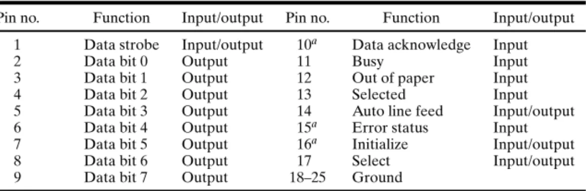
The connection between the dust measurement device and the computer is shown in Fig. 4.
As seen in Fig. 4, six-wired cable is used between the computer and the particle measurement device. One of the lines constitutes the bit to trigger and shut the system. Four of the lines are used for data input, and the last one is used for GND.
Connection among the multiple environments selector, the computer, and the dust measurement device is shown in Fig. 5.
After 0.2 cf. of air is sampled, the vacuum pump stops and then particles therein are counted by the device. Measurement results are displayed on the digital displays. Channel-1 displays the number of particles of 0.5 µm and above, channel-2 displays the number of particles of 1.0µm and above, channel-3 displays the number of particles of 5.0µm and above, and channel-4 displays that of particles of 10 µm and above. The process of measurement has been conducted for an air of a volume of 0.2 cf. (5663.2 cm3). In order to normalize measurement results to the number of particles in a volume of 1 cf., the results are multiplied by 5.
Fig. 5. Block diagram of particle counting system.
By sampling organic and inorganic particles in an aerial environment, the par-ticle measurement device counts the parpar-ticles within a given volume (air volume of 1 m3). Very sensitive laser detectors are used in and for the process of counting. The particles contained in unit volume sampled from the environment, are counted cumulatively in the laser sensor as four groups.
The process of dividing particles into four groups by means of sizing is made through a reference voltage circuit previously calibrated. The four separate size (volt-age) levels at the output of the reference voltage circuit are compared to the signal coming from the laser sensor output. At the end of this process of comparing, the out-put signals are divided into four separate groups according to the reference voltage levels.
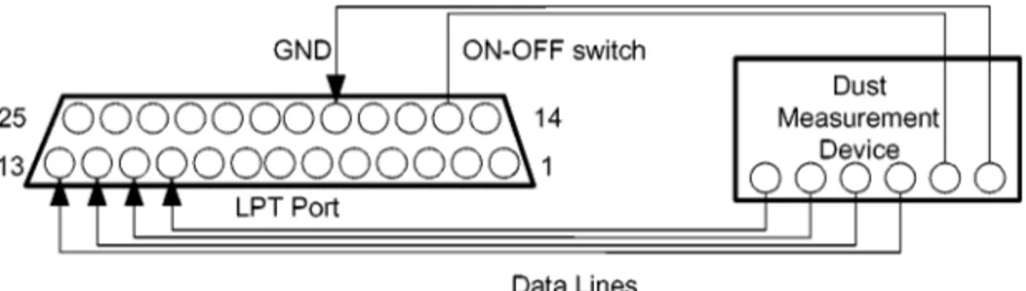
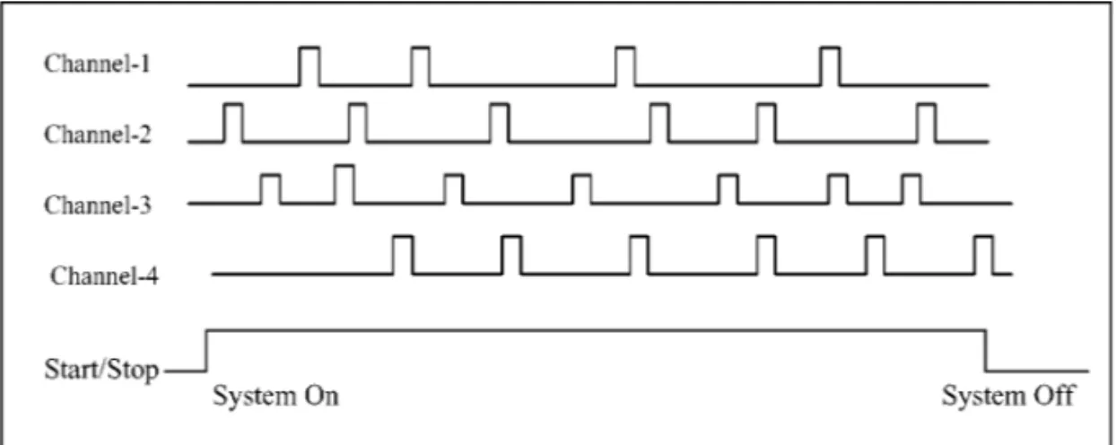
These signals at the four channels are transferred to the computer. The signals are represented as TTL (Transistor–Transistor–Logic) signal. Each particle is defined as a 1-pulse electrical sign.
As shown in Fig. 6, each pulse sent from the four channels to the computer is 5 V. These signals are digitized by the computer. High level signals are rep-resented as logic 1 and the low level signals are reprep-resented as logic 0 by the computer.
These pulses defining the particles are transferred to the computer through previously defined parallel port. The four pins of the parallel port are designated as input pins for counting four separate channels. And, along with these, one pin is designated as a start/stop pin to initiate or to shutdown the system. Whenever the
low level signal at this start/stop pin will be shutdown the system, and the signals arriving to the port will be ignored. It is also possible make some processes using user interface software. These are: when the process of transferring particle signals to the computer will begin, for how long arriving data will be collected and stored, and when the process of transferring will be ended.
The period in which the control signal keeps coming is the process in which counting takes place. It is evaluated by computer and the results are recorded and displayed on the screen and if desired they are stored in disk.
Usage of the User Interface Software
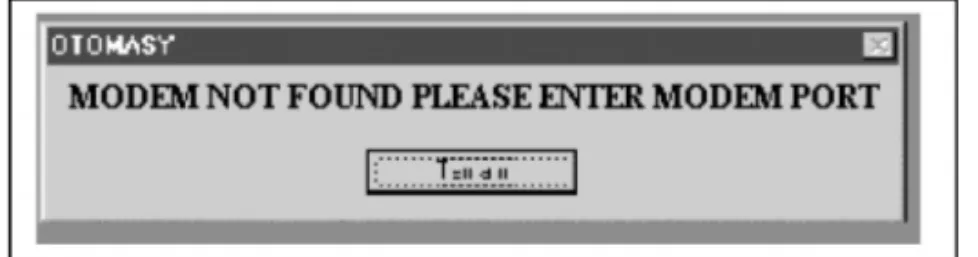
When the user interface program runs, the main menu comes on screen. The screenshot of main menu is shown in Fig. 7. If there is a modem installed in the PC. The modem needs to be configured at the COM2 port (serial communication port) of the PC. If the modem is not installed at COM2, the message shown in Fig. 8 will appear on the screen. You will have to configure the serial communication port through which your modem is connected.
After making required configuration, the program will start. If there is no mo-dem, the program will start operation restrictedly.
The program has been designed as user friendly. Users can easily use and man-age the system. Such actions as grouping screen data by using frames, and reading, viewing, managing, and directing values can be done easily.
Management of Program
The program can be managed by using shortcut keys, pull-down menus, and command buttons.
System Status
The program has both a header option and check boxes showing system status. Either of them is checked, the header is automatically changed as “SYSTEM ON” or “SYSTEM OFF.”
In the Received Value section, after the system is started, the input values corre-sponding to the pin which receives signals will start to increase. In the Warning Lines section, warning threshold levels for each input will be input by the users. Most of the industrialized countries have set their own standards. These standards are based on measuring the presence of particles of varying sizes and numbers.
Fig. 8. Warning message for the modem comport.
The program has been developed for controlling several operating rooms. In Select Room section seen in Fig. 9, the operating room, the dust status of which is to be controlled, is selected, and the system is triggered.
In case the data arriving from the particle measurement device exceed the warn-ing levels, the computer triggers the selected warnwarn-ing system. There are four types
Fig. 10. Warning types selection screen.
of warning as shown in Fig. 10. These are:
Audio Warning: When this warning type is selected, in case any input value exceeds the threshold level, the computer will play the sound file (.wav) previously selected through the sound card, and warn relevant personnel.
Visual Warning: Two options are available. The first option is to warn through screen display. In the second one, outgoing signals are sent to operate other visual warning devices through 378H address of the parallel port.
Call Warning: One of the most important features of the system is that any message could be sent to any person through the telephone using fax-modem card. No Warning: When this option is selected, the warnings will be deactivated.
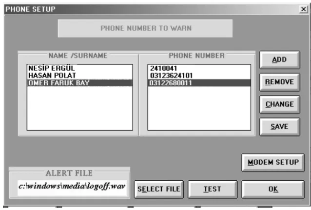
When the phone setup appears, names and corresponding telephone numbers are listed on this screen (see Fig. 11). The person to be warned on the phone is
selected using this menu. Then, the sound file that needs to be played to this person is seen under the name Alert File. If this section is empty, a new file is selected using Select File button.
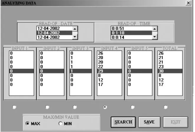
In Analyzing Data section, the received data from the dust measurement device are stored after being displayed on the main screen. The Analyzing Data screen shown in Fig. 12 is accessed from File Process menu.
As seen in Fig. 12, inputs frame, reading dates frame, reading duration frame, max/min value selection frame are available on the Analyzing Data screen. There are check boxes right below the inputs frame. Clicking on any value with the mouse, the other data will simultaneously change, and positioned on the data they have received on the same date and duration.
The system should be OFF before exiting the program, otherwise it is not pos-sible to exit the program. If the user selects the EXIT button while the system is in use, the message will appear on the screen “You cannot quit while system is in use.”
Hardware Requirements
Hardware Requirements to run the user interface software are as follows: Windows 95 and above for operating system, at least 8 MB of RAM, 5 MB of free space in hard disk, a 16-bit Sound Blaster sound card, a modem with voice feature, and a link cable is needed between the sound input of the modem and the out port of the sound card.
CONCLUSION
In this study, signals coming from the operating rooms were evaluated by the computer by being controlled through the parallel port of the computer without the need for any interface card at all. The computer reacts to any impact coming from the operating rooms, and warns any authorized people in the outer environment by making use of required devices. These warnings are by audio, by visual, and by phone. Furthermore this program, along with the particle measurement device, intro-duces an innovation to hospital automation by means of being included in the indus-trial automation and indusindus-trial hygiene group.
REFERENCES
1. Jaffal, A. A., Nsanze, H., Bener, A., Ameen, A. S., Banat, U. M., and El Mogheth, A. A., Hospital airborne microbial pollution in a desert country. Environ. Int. 23(2):167–172, 1997.
2. Raza, S. H., Rana, K., and Murthy, M. S., Indoor aerobiological pollution in certain Indian domestic environment. Environ. Int. 15:209–215, 1989.
3. Dharan, S., and Pittet, D., Environmental controls in operating theatres. J. Hosp. Infect. 51:79–84, 2002. 4. Charnley, J., and Eftekhar N., Postoperative infection in total prosthetic replacement arthroplasty of
hip joint. Br. J. Surg. 56:641–649, 1969.
5. Lidwell, O. M., Lowbury, E. J. L., Whyte, W., Blowers, R., Stanley, S. J., and Lowe, D., The effect of ultraclean air in operating rooms on deep sepsis in the joint after hip or knee replacement: A randomised study. Br. Med. J. 285:10–14, 1982.
6. Gosden, P. E., MacGowan, A. P., and Bannister, G. C., Importance of air quality and related factors in the prevention of infection in orthopedic implant surgery. J. Hosp. Infect. 39:173–180, 1998. 7. Friberg, B., Friberg, S., and Burman, L. G., Correlation between surface and air counts of particles
carrying aerobic bacteria in operating rooms with turbulent ventilation: An experimental study. J.