KADIR HAS UNIVERSITY
GRADUATE SCHOOL OF SCIENCE AND ENGINEERING
BANDWIDTH ALLOCATION AND TRAFFIC SHAPING IN
MOBILE BROADBAND NETWORKS USING DEEP PACKET
INSPECTION
RAMAZAN ÖZBİLEN
R A M A Z A N Ö Z B İL E N M as te r T he sis 2015
BANDWIDTH ALLOCATION AND TRAFFIC SHAPING IN
MOBILE BROADBAND NETWORKS USING DEEP PACKET
INSPECTION
RAMAZAN ÖZBİLEN
B.S., Computer Engineering, Kadir Has University, 2010 M.S., Computer Engineering, Kadir Has University, 2015
Submitted to the Graduate School of Science and Engineering in partial fulfillment of the requirements for the degree of
Master of Science in
Computer Engineering
KADIR HAS UNIVERSITY
KADIR HAS UNIVERSITY
GRADUATE SCHOOL OF SCIENCE AND ENGINEERING
BANDWIDTH ALLOCATION AND TRAFFIC SHAPING IN
MOBILE BROADBAND NETWORKS USING DEEP PACKET
INSPECTION
RAMAZAN ÖZBİLEN
APPROVED BY:
Assist.Prof.Dr. Taner ARSAN Kadir Has University
Prof.Dr. Sema OKTUĞ Istanbul Technical University Assist.Prof.Dr. Tamer DAĞ Kadir Has University
"I, Ramazan Özbilen, confirm that the work presented in this thesis is my own. Where information has been derived from other sources, I confirm that this has been indicated in the thesis"
_______________________ RAMAZAN ÖZBİLEN
ABSTRACT
BANDWIDTH ALLOCATION AND TRAFFIC SHAPING IN MOBILE BROADBAND NETWORKS USING DEEP PACKET INSPECTION
RAMAZAN ÖZBİLEN
Master of Science in Computer Engineering Advisor: Assist. Prof. Dr. Taner ARSAN
JANUARY,2015
In this thesis, it is intended to estimate bandwidth and control mobile data usage by utilizing PCC (Policy and Charging Control) function. According to increase in number of mobile devices, data explosion occurs. It is becoming a must to analyze traffic and sharing resources between subscribers according to their usage habits. It is aimed to provide better a better connected world with service assurance by sharing available bandwidth and estimate it to users according to their needs by protocol level and service based QoS. Due to increase in amount of services like Facebook, Twitter, Mobile TV, in general IP networks, providing service assurance becomes more important day by day. That's why the issue of controlling bandwidth is raised.
In the most basic sense, system architecture consists of three main components: A cell phone to generate user based traffic, Gateway GPRS Support Node (GGSN) for Deep Packet Inspection (DPI), and Policy and Charging Rule Function (PCRF) for initiating PCC or Non-PCC rules to GGSN according to services that are needed by user. Shortly, the main idea in this thesis is assigning service based QoS to subscribers to provide better service assurance according to their usage.
As thought, the reason of preparing this study is to show the dramatical increase in service based traffic, to explain insufficiency in current bandwidth estimation approaches, and the idea of what can be used in the work of providing better service assurance to an end user. PCRF is the best component for providing required bandwidth when they needs.
ÖZET
MOBIL GENİŞ BANT AĞLARDA DERİN PAKET TARAMASI İLE BANT GENİŞLİĞİ ATAMASI VE TRAFİĞİN ŞEKİLLENDİRİLMESİ
RAMAZAN ÖZBİLEN
Bilgisayar Mühendisliği, Yüksek Lisans Danışman: Yrd.Doç.Dr.Taner ARSAN
OCAK,2015
Bu çalışmada, günümüzde gittikçe artan akıllı cihazlar ile sınırlı kapasitedeki bant genişliğinin policy ve ücretlendirme fonksiyonu kullanılarak, optimum düzeyde kullanılması ve kullanıcı deneyiminin bu doğrultuda mümkün olan en üst düzeye çıkarılması hedeflenmektedir. Mobil cihazlar üzerinden kullanıcıların network üzerinde yoğun şekilde kullandığı uygulamalar analiz edilerek, bu uygulamaların bant genişliğini düşüren arka plan trafiği ve diğer uygulamalara göre network paket analizi ile önceliklendirilmesi ve aynı hücre altından servis alan kullanıcı trafiğinin çeşitli analizler ile uygun bir şekilde bölüştürülmesi amaçlanmaktadır. Bu sayede mobil internet kullanıcıları en iyi deneyime ulaşabilecek ve operatör tarafındaki transmisyon kapasite maliyetleri ihtiyaca göre bant genişliği ataması ve paket önceliklendirmesi ile minimuma düşürülebilecektir.
Sistem en basit şekli ile üç ana parçadan oluşnmaktadır. Trafiğin analizi ve yönelndirilmesi için sürekli kullanımı olan bir mobil cihaz, paket analizi ve analiz doğrultusunda uygun bandwidth yönetimini içeren kuralların gerçekleştirilmesi için Gateway GPRS Support Node (GGSN), PCC ile PCC olmayan uçtan uca kuralların anlık network dinamikleri ve kullanılan uygulamaya göre atanmasını sağlayan Policy and Charging Rule Function (PCRF). Kısaca projenin amacı çevresel şartlara göre değişebilen bandwidthin en uygun şekilde dağıtımı ve uygulama bazlı paket önceliklendirmesi yapılarak en yüksek verimliliğe ulaşılmasıdır.
Bu uygulama mimarisinin amacı, günümüzde giderek artan akıllı cihaz sayısı ve bu doğrultuda yükselen mobil internet kullanımını en iyi kullanıcı deneyimi ile sunmak, client tarafında herhangi bir değişiklik yapılmasına gerek olmaksızın network optimizasyonu ile daha düşük maliyetlerde daha verimli servis kullanımını sağlamaktır.
Acknowledgements
First of all, I would like to thank my supervisor Assist. Prof. Dr. Taner ARSAN who always supported and helped me during the thesis period. Thanks for his useful advices and encouragement.
Last but not least, I would like to thank my family for their patience, support and encouragement. Words are not enough to express my thankfulness, as well as to my friends.
Table of Contents
Abstract vi
Özet vii
Acknowledgements viii
Table of Content x
List of Figures xiii
List of Abbreviations xv
1 Introduction 1
1.1 Overview...1
1.2 Related Work...2
1.3 Service Assurance...3
1.3.1 Benefits of Applying Service Assurance...3
2 GPRS Network Elements and Interfaces Overview 4 2.1 Radio AccessNetwork...4
2.1.1 GPRS EDGE Radio Access Network - GERAN(2G)...4
2.1.2 Packet Controller Unit –PCU...4
2.1.3 Universal Terrestrial Radio Access Network - UTRAN(3G).5 2.1.4 Radio Network Controller – RNC...5
2.2 Core Network...5
2.2.1 Home Location Register – HLR...5
2.2.2 Serving GPRS Support Node – SGSN...5
2.2.3 Gateway GPRS Support Node – GGSN...5
2.2.4 Policy and Charging Rules Function – PCRF...6
2.3 PDP Context...6
2.3.1 Routing Area Information (RAI)...6
2.3.2 Network Service Access Point Identifier (NSAPI)...7
2.3.3 Access Point Name (APN)...7
2.3.4 QoS Profile...8
2.3.5 RAT Type...9
3 Concept of Quality of Service 11
3.1 Overview... 11
3.2 Delay... 11
3.3 Jitter... 11
3.4 Packet Loss Ratio... 11
3.5 Traditional Packet Transmission Application... 11
3.6 New Applications Requirements... 11
3.7 QoS Negotiation... 12
3.7.1 Negotiating QoS on the network side... ... 12
3.7.2 Controlling QoS on the network side... 14
3.8 QoS Upgrade... 14
4 Concept of Bandwidth Allocation and Traffic Shaping 17 4.1 Concept of Bandwidth Allocation...17
4.2 Concept of Traffic Shaping...20
4.2.1 Token Bucket & Leaky Bucket...20
4.2.2 Proposed Algorithm: Dual Token Bucket...22
4.2.3 Traffic shaping...24
4.3 Implementation of Bandwidth Allocation and Traffic Shaping....26
4.3.1 General Architecture in Basic...26
4.3.2 QoS Policy Control Logic...27
4.3.3 General Policy Control Logic of Facebook Service...28
5 SOAP and WEB SERVICES 31 5.1 Web Services...31
5.2 Advantages of Using Web Services...31
5.3 WSDL (Web Services Description Language)...32
5.4 SOAP (Simple Object Access Protocol)...32
5.5 REST (REpresentational State Transfer) ………...33
5.6 REST and SOAP...34
5.7 Service Provisioning...34
6 Deep Packet Inspection (DPI) 35 6.1 What is DPI...35
6.3 DPI Functions...37
6.3.1 Shallow Packet Inspection (SPI)...40
6.3.2 Service Awareness (SA)...40
6.4 Encryption: The Death of DPI...41
6.4.1 Heuristic Analysis (H-SA)...42
7 Testbed and Test Results 43 7.1 TC1 – Allocate 256K of Bandwidth to Subscriber...44
7.2 TC2 – Limit Bandwidth to 256K with Traffic Shaping...45
7.3 TC3 – URL Based Bandwidth Management...47
7.4 TC4 – Detection of VOIP and TETHERING Traffic... 50
7.5 Performance Comparison after Changing Traffic Handling Priority and Effects on User Experience...52
8 Conclusion and Future Work 54 8.1 Conclusion...54
8.2 Future Work...54
List of Figures
Figure 1: Establishing Service Assurance...3
Figure 2: Network Elements and Interfaces in MBB Networks...4
Figure 3: IP Header in PDP Context Message...6
Figure 4: Routing Area Information in PDP Context Message...6
Figure 5: NSAPI Information in PDP Context Message...7
Figure 6: Access Point Name in PDP Context...7
Figure 7: QoS Profile and RAT Type in PDP Context...8
Figure 8: QoS Traffic Classes...9
Figure 9: Gx Diameter Messages...10
Figure 10: QoS Negotiation Signaling...13
Figure 11: QoS Upgrade Signaling...15
Figure 12: Bandwidth Allocation in Mobile Broadband Networks...17
Figure 13: Bandwidth Allocation in Mobile Broadband Networks Detailed...18
Figure 14: Policy Control Scenario...19
Figure 15: Token Bucket Algorithm...20
Figure 16: Traffic Shaping Using Token Bucket...21
Figure 17: (a) Leaky Bucket with Water, (b) Leaky Bucket with Packets...22
Figure 18: Dual Token Bucket algorithm...23
Figure 19: Differences between Single and Dual Rate Token Bucket...23
Figure 21: General UPCC Architecture for Bandwidth Assignment...26
Figure 22: QoS Policy Control...27
Figure 23: 256Kbps Bandwidth Allocation Signaling...27
Figure 24: 7.2Mbps Bandwidth Allocation Signaling...28
Figure 25: Limit 128K Traffic Shaping Signaling...28
Figure 26: Facebook Rule Logic...29
Figure 27: Facebook Rule Install Diameter Signaling...29
Figure 28: Exhausted Service Quota and Quota Cycle Reset...30
Figure 29: Web Service System...31
Figure 30: Web service to Web service in sender-receiver mode...32
Figure 31: RESTful Interface for Application QoS...33
Figure 32: Data Traffic per Month...35
Figure 33: Mobile Data Growth...36
Figure 34: Number of Smart Phone and Tablet Owners by Year...36
Figure 35: DPI, Old & New Approaches...39
Figure 36: DPI in OSI Layers...40
Figure 37: Change in Active Users of Social Platforms...40
Figure 38: Heuristic Analysis (H-SA)...42
Figure 39: GPRS Flow Diagram...43
Figure 40: IO Graph of 256K of Bandwidth...44
Figure 41: AVG Speed Graph of 256K of Bandwidth (E2E)...45
Figure 42: IO Graph of 256K of Bandwidth Limiting (Traffic Shaping)...46 Figure 43: AVG Speed Graph of 256K of Bandwidth Limiting (Traffic Shaping)46
Figure 46: IO Graph of URL Based QoS (Limited Facebook)...49 Figure 47: AVG Speed Graph of Facebook With Limitation...49
Figure 48: Voip Detection with Heuristic Analysis...50 Figure 49: Dynamic QoS and THP assignment in Case of A Network Congestion52 Figure 50: Traffic Flow Detection According to URL...53
List of Abbreviations
3G 3rd Generations
3GPP 3rd Generation Partnership Project AF Application Function
API Application Programming Interface BA Bandwidth Allocation
BSS Base Station Subsystem CA Certificate Authority
DB Database
ECMA European Computer Manufacturers Association
ETSI The European Telecommunications Standards Institute GGSN Gateway GPRS Support Node
GPRS General Packet Radio Service
GSM Global System for Mobile Communications IDE Integrated Development Environment HTTP Hyper-Text Transfer Protocol
HTTPS Secure Hypertext Transfer Protocol
IEC The International Electrotechnical Commission ISO International Organization for Standardization IP Internet Protocol
MYSQL My Structured Query Language OS Open Source
OSI Open Systems Interconnection PCC Policy Control and Charging PDP Packet Data Protocol
REST Representational State Transfer RF Radio frequency
RFID Radio-frequency identification SGSN Serving Gateway Support Node SMS Short Message Service
SMTP Simple Mail Transfer Protocol SOAP Simple Object Access Protocol SQL Structured Query Language SSL Secure Socket Layer
TCP Transmission Control Protocol TLS Transport Layer Security TS Traffic Shaping
UE User Equipment UI User Interface
UPCC Unified Policy and Charging Controller URL Uniform Resource Locator
WCDMA Wideband Code Division Multiple Access WLAN Wireless Local Area Network
WSDL Web Service Definition Language W3C The World Wide Web Consortium XML Extensible Markup Language
Chapter 1
Introduction
Computer networks have too much importance in every part of our life. Not just in companies, also too many people use them in their daily life. Mobile phone usage is growing up so fast. Everyone is using internet on their phones to check something instantly and to communicate with their friends, especially in social media. Today, a mobile phone can handle more services, not used for just voice communication, such as mobile TV, streaming, VoIP, internet browsing etc. If one uses a part of these services, he wants this service to work properly. No one wants to miss a business call while watching one episode of his favorite series.
Technology improves quickly. According to this improvement, smart phone prices fall, and it becomes much easier to gain access to them. Everything is getting more mobile in these days. Also people start to communicate over VoIP and the amount of users that are using VoIP instead of legacy call services are getting higher.
Because of that increase in internet usage there is a new gap born in bandwidth assignment. Everyone is getting the same bandwidth for all applications that they are using. Thus, while downloading something over internet, they can’t communicate properly on VoIP. There are lots of advantages of being able measure and guarantee quality of service in a specific application. Prioritize traffic usage, assigning URL based QoS values or application based bandwidth is becoming more and more important day by day.
As an operator, it has also too much importance to divide available bandwidth to subscriber of their services. Bandwidth of a link is limited. Every usage is aggregating inside this link. The best way of guarantee a certain quality in this usage is prioritize in traffic flows and bandwidth based on usage of a specific application.
1.1 Overview
This thesis aims to provide service assurance in specific applications that is becoming more and more important in today’s networks. Additional benefits, the evolution in traffic management, will be discussed in next chapters. And in the following chapter the scope of project to which ways will be used to manage this kind of traffic will be discussed. Current deep packet Inspection technologies, policy functions, traffic classification and general inspection overview will be focused on coming chapters.
1.2 Related Work
There has been a lot of research on this area. Many techniques have been proposed and lots of studies have been done.
One critical issue is that traffic shaping cannot allocate excess bandwidth to active subscribers in the long term. This is because the traffic shaper based on token bucket cannot take into account the status of other subscribers. A large-size token bucket enables sharing of excess bandwidth among active subscribers, but only in the short period of time corresponding to the token bucket size. In the journal discusses the major requirements for the excess bandwidth allocation in shared access networks and proposes, ISP traffic control schemes based on core-stateless fair queuing (CSFQ) and token bucket meters. [2]
In order to accommodate the rapid increase in speed and bandwidth demands, many methods and algorithms were developed and implemented. The conference paper is about algorithms that allow flattening the utilization profile of network resources by optimizing network resources. In addition, we tested various scheduling techniques to reduce the effect of traffic delays. [3]
How to deal with increasing requirements for Network Intelligence and QoS signaling in IP multimedia subsystem of UMTS. UMTS network needs to find QoS requests of IP multimedia session through signaling protocol before it reserves resources for communication. Network intelligence is gathered by various techniques from evolving network functions, LTE (long term evolution) and IMS (IP multimedia subsystem). Nl is utilised to build rules under policy and charging control (PCC) standard architecture, which instructs the bearer network to enforce them. Latest mobile standards enhance the collaboration between core network (IMS) and access (e.g. LTE), through events reporting. Advanced heuristic DPI (deep packet inspection tools) can deliver more accurate user and session intelligence. [4]
High-speed Internet services, IP video, and Smartphone applications significantly increase the average revenue per user. For these high bandwidth services to become profitable, the cost per bit must drop, which packet and optical technologies make possible to a degree. Packet Network architectures have been and will be constantly evolving to adapt to new applications, services and requirements. In the past, newly developed packet network architectures have been mainly focused on the transport plane, whose purpose is to deliver user packets. End-to-end and manage transport resources such as bandwidth, buffers, packet processing elements, etc. [8]
The successful deployment of Universal Mobile Telecommunication System (UMTS) is heavily dependent on Quality of Service (QoS) to be achieved. The main focus of this thesis is traffic conditioning related issues for QoS provisioning in UMTS. Assuming an end-to-end QoS scenario supported by IntServ or/and Diffserv architectures, the thesis initially presents an all nodes traffic conditioning-enabled framework in UMTS. [6]
1.3 Service Assurance
Service assurance is the entire of policies to ensure service quality to provide predefined values for best user experience.
In practice, the pinpoint of service assurance is to identify faults as soon as possible and to minimize bad effects on user. In today’s network it is more important to guarantee a service rather than just delivering it.
1.3.1 Benefits of Applying Service Assurance
Implementing service assurance has lots of advantages. Quality is a key value for a subscriber. Assuring the expected quality makes your network more trustable.
Dividing service into pieces makes it easier to manage and troubleshoot the network. Also operational expenditure (OPEX) will be decreased because of the improvement in operational processes and network transmission cost. When an service assurance is applied on a shared network capacity, network usage will be more efficient. It will reduce the network resource requirements because network usage will be more scalable and a great quality level will be achieved. [9]
Service Assurance takes cares of the promised service according to requirements. Besides, creating and activating process it is needed to address any issues subscribers might have with its service. That’s why Service Assurance has as much as importance with the creation process in intelligent and automated networks.
Chapter 2
GPRS Network Elements and Interfaces Overview
This chapter provides a brief explanation about General Packet Radio Service (GPRS). Network equipments, interfaces between these equipments and general architecture are explained. GPRS has a complex network architecture that contains air interface and core interfaces as can be seen in the figure below:
Figure 2: Network Elements and Interfaces in MBB Networks [24]
2.1 Radio Access Network
Radio Access Network is the air interface with base station system in the network. GSM/UMTS includes GERAN (GPRS EDGE Radio Access Network) and UTRAN (Universal Terrestrial Radio Access Network).
2.1.1 GPRS EDGE Radio Access Network – GERAN BTS-BSC
Base Station Subsystem contains BTS (Base Transceiver System) that is used for transmitting and receiving radio signals and BSC (Base Station Controller) that controls hundreds of BTS and relation between them. BSC is connected to PCU for
2.1.2 Packet Controller Unit – PCU
Packet Control Unit performs tasks for packet data and directly connected to SGSN over Gb interface. Channel allocation between voice and data is under control of BTS but if BTS allocates a channel to data PCU takes its control completely. BSS systems, including BTS, BSC and PCU are belong to GERAN architecture.
2.1.3 Universal Terrestrial Radio Access Network – UTRAN NodeB-RNC
Universal Terrestrial Radio Access Network contains NodeBs (UMTS equivalent of BTS) and RNCs (Radio Network Controller). It controls connectivity between UE and Core Network.
2.1.4 Radio Network Controller – RNC
Radio Network controller is responsible for controlling NodeBs located under it and handles radio resource management. It is connected over Iu interface to Core Network.
2.2 Core Network
Core Network is the main part of a network. Main functions like services and subscriptions are handled in this part of the network. Switches, routers and mobility management devices are located in Core Network.
2.2.1 Home Location Register – HLR
Home Location Register is the main database for controlling every mobile subscriber authorized to use a GSM operator. Primary network profile of subscriber is stored in HLR. HLR is directly connected to SGSN over Gr interface.
2.2.2 Serving GPRS Support Node – SGSN
Serving GPRS Support Node is responsible for delivery of packet data in a defined geographic area. [10] It routes packets to the connected Gateway Support Node over Gn interface on a GTP tunnel and controls mobility management.
2.2.3 Gateway GPRS Support Node – GGSN
Gateway GPRS Support Node is the main node that connects GPRS network to packet switched networks. It is responsible for routing packets into Packet Data Protocol (PDP) to related SGSN over Gn interface and to a packet switched network over Gi interface. IP pool management, Deep Packet Inspection (DPI), traffic management and QoS enforcement are controlled by GGSN.
2.2.4 Policy and Charging Rules Function – PCRF
PCRF is an equipment for policy function of real-time bandwidth and charging in multimedia broadband networks. PCRF takes control of policy decisions on its own according to given conditions. Send PCC or Non-PCC rule to GGSN over Gx interface for controlling high bandwidth applications, QoS guarantees and URL based speed allocations.
2.3 PDP Context
PDP context stands for Packet Data Protocol context. It is a connection between a user equipment and GGSN passing through SGSN. It includes subscriber information to forward call to next hop.[10] When user wants to communicate with an external IP address, PDP context must be activated before sending data through GTP tunnel between SGSN and GGSN.
At first a control message (create PDP context request) comes from SGSN to GGSN that includes source and destination addresses (Figure 3), RAI (Figure 4), NSAPI (Figure 5), APN (Figure 5), DNS (Figure 6), QoS Profile (Figure 7), and RAT type (Figure 7).
Figure 3: IP Header in PDP Context Message
2.3.1 Routing Area Information (RAI)
RAI is a location area in PS domain. It specifies the identity of SGSN that UE is connected. (3GPP TS 23.003.) It is required for mobility management.
2.3.2 Network Service Access Point Identifier (NSAPI)
NSAPI is a dynamically allocated number (provided by MS) between 0 and 15 for a PDP context in a unique session. When UE creates a PDP context activation request, it sends an NSAPI value to identify its session. In case of a routing area update, It changes this value and its used as an identifier of GTP tunnel between SGSN and GGSN.
Figure 5: NSAPI Information in PDP Context Message
2.3.3 Access Point Name (APN)
APN tells what kind of a connection will create. An APN must be configured for establishing a data connection with a carrier. It includes Mobile Country Code (MCC) and Mobile Network Code (MNC) information. Also internet DNS information is located under APN. These values are unique for each operator and included in PDP context message like in the figure 6.
2.3.4 QoS Profile
It includes delay and traffic class, erroneous service data unit (SDU) and bit rate information. Then related parameters are changed by PCRF.
Network Services are considered end-to-end. An End-to-End Service has a Quality of Service (QoS) which is provided for the user of a network service. To realize a certain network QoS a Bearer Service with clearly defined characteristics and functionality is to be set up from the source to the destination of a service.
Figure 7: QoS Profile and RAT Type in PDP Context
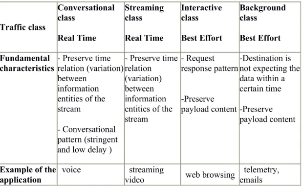
There are four different QoS traffic classes(Figure 8): Conversational Class
Streaming Class Interactive Class Background Class
Traffic class Conversational class Real Time Streaming class Real Time Interactive class Best Effort Background class Best Effort Fundamental
characteristics - Preserve timerelation (variation) between information entities of the stream - Conversational pattern (stringent and low delay )
- Preserve time relation (variation) between information entities of the stream - Request response pattern -Preserve payload content -Destination is not expecting the data within a certain time -Preserve payload content Example of the application voice streaming
video web browsing
telemetry, emails
Figure 8: QoS Traffic Classes
2.3.5 RAT Type
It identifies the radio access technology. It can be GERAN(2G), UTRAN(3G), EUTRAN(4G) according to connection type.
According to 3GPP standards, RAT type value 1 represents UTRAN, 2 GERAN, 3 WLAN, 6 EUTRAN [26].
2.4 Diameter Protocol
Diameter is an authentication, authorization and accounting protocol. It is developed to replace RADIUS protocol.
2.4.1 Diameter Protocol on Gx interface
AVP code values from 0 to 255 are reserved for Radius and values between 256 and 16777213 are reserved for specific commands. In Gx interface for PCRF signaling below codes are being used.
Command-Name Abbr. Code Explanation
Abort-
Session-Request ASR 274 Sends for requesting identified session id be stopped.
Abort-
Session-Answer ASA 274
Response message to an ASR message. Indicates a result code.
Credit-
Control-Request CCR 272
Credit control is an application to provide real-time charging.
Credit-
Control-Answer CCA 272 Response message to an CCR message. Indicates a resultcode.
Capabilities-
Exchange-Request CER 257
Communication between to Diameter peers to establish TCP connection.
Capabilities-
Exchange-Answer CEA 257
Response message to a CER message. Indicates a result code.
Device-
Watchdog-Request DWR 280 If there is no CER/CEA message between peers for atime. DWR is sending to check peer device.
Device-
Watchdog-Answer DWA 280
Response message to an DWR message. Indicates a result code.
Re-Auth-Request RAR 258
Diameter server peer (PCRF) can send a re-authentication-request to client peer (PCEF/GGSN) to inform changes in an active session.
Re-Auth-Answer RAA 258
Response message to an RAR message. Indicates a result code.
Figure 9: Gx Diameter Messages
In PDP context activation process, Credit Control Request (CCR) message is sent to PCRF to get required charging rule information. It sends a session id, origin host and realm information, network type and requested QoS information. A random session id is generated for each session. PCRF identifies the rule to be sent to GGSN according to these parameters and responds with a Credit Control Answer message to GGSN. This message includes QoS information according dedicated services and network conditions to this subscriber.
Chapter 3
Concept of Quality of Service
3.1 Overview
QoS is a term that describes relations between demands and supplies. It is a measurement of quality that is supplied to meet demands of subscriber. Sometimes, legacy QoS does not provide accurate results [6]. It only focuses on quality of service under certain conditions. Some applications can use their own protocols but their application type is still same. (e.g. Skype is using its own protocol but it is still a VoIP application.)That’s why assigned QoS can be defective. On the Internet, QoS is using for evaluating the ability of the network to transmit packets includes delay, jitter, and packet loss ratio.
3.2 Delay
Network delay is an important characteristic of a telecommunication network. It means how long it takes a packet transmission from source node to destination. The reason for delay can be queues or network congestion.
3.3 Jitter
Jitter is the difference between the delay of packets (successive) in a flow. It has effects on audio and video streams causes corruption of motion and loss of video. Against this kind of issue a jitter buffer can be used.
3.4 Packet Loss Ratio
Packet loss is the failure percentage in the transmission of packet to their destination. IP is a best effort service; if network guarantees reliable delivery it should apply store and forward mechanism. But for some services, reliability is not needed. That’s why in a live audio or a video stream, packets should be delivered in a short time. To achieve this, IP allows routers to drop packets if transmission line is too busy or the transmitted packet is broken.
3.5 Traditional Packet Transmission Application
It is difficult to ensure QoS in the traditional IP network. Because routers in the network handle packets according to First In, First Out (FIFO) method for packet transmission. All packets share the bandwidth of network. Resources are used according to arrival times of packets. Traditional best effort mode is applied on services such as World Wide Web, VoIP, and email but has no specific bandwidth and delay.
3.6 New Applications Requirements
By the rapid technology development, number of networks connected to internet is also increased to a large amount. Resources are limited and applications demand
larger bandwidths, little jitter and delay. [23] For example social services like Facebook and Twitter is getting %47 of internet usage [27], and this kind of applications include voice and video streaming that need larger bandwidth values. For this kind of things subscribers are expecting improved service transmission. Or for other applications, these services should be limited. So, different QoS should be provided for different services.
3.7 QoS Negotiation
In traditional Global System for Mobile Communications (GSM) or UMTS networks, NEs negotiate GPRS QoS parameters with each other. During the negotiation, the values of the following QoS parameters are generally decreased: MS-requested QoS, subscribed QoS in the home location register (HLR), SGSN-defaulted QoS, and QoS capability of the SGSN and peripheral NEs. This mechanism ensures that end-to-end QoS on the mobile packet switched network is lower than the subscribed QoS. However, the QoS negotiated on the network side may not meet the requirements for services at the application layer because whether the QoS is proper depends on the associated service type. As a result, services cannot operate normally and network resources are wasted. To prevent wasting network resources, 3GPP R7 provides the QoS control function on the network side, which allows the network side to raise QoS based on the specific service type. [5]
QoS can be determined in two modes:
Negotiating QoS on the network side Controlling QoS on the network side
3.7.1 Negotiating QoS on The Network Side
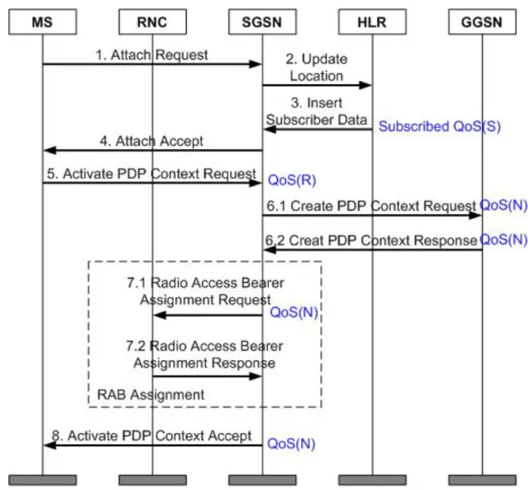
The SGSN is the center of this negotiation and responsible of negotiation for MS-requested QoS , given QoS in HLR, GGSN initiated PDP context update. After receiving SGSN requested QoS other equipments negotiate QoS according to their capabilities. If UE rejects the QoS on the network side, starts PDP deactivation. This signaling can be found in the figure below:
Figure 10: QoS Negotiation Signaling
QoS Negotiation Procedure in Network Side
QoS (R) stands for requested QoS requested in PDP context activation. QoS (S) stands for given QoS in HLR after network attach mechanism.
QoS (N) stands for negotiated QoS by RNC, SGSN and GGSN. After the negotiated QoS SGSN compares subscribed and negotiated QoS.
The QoS negotiation procedure is described as follows: [3GPP] 1. The MS sends an attach request to the SGSN.
2. If the SGSN number has changed since the last detach, or if the MS attaches to the network for the first time, the SGSN instructs the HLR to obtain subscription data.
3. The HLR sends the Insert Subscriber Data message carrying the subscribed QoS to the SGSN.
5. The MS sends an Activate PDP Context Request message carrying the requested QoS to the SGSN. The MS can also set the value of the QoS
parameter carried in the Activate PDP Context Request message to 0. 6. The SGSN checks whether the MS can apply for the relevant QoS profile
based on the subscribed QoS. If the MS can apply for the relevant QoS
profile and the SGSN has sufficient resources (including the bandwidth and the load-related resources), the SGSN sends a Create PDP Context Request message to the GGSN. If the SGSN does not have sufficient resources, it restricts the QoS profile, degrades the QoS, or rejects the PDP context activation request.
7. The SGSN sends a Radio Access Bearer Assignment Request message to the RNC based on theQoSnegotiated with the GGSN.
8. If the RAB is successfully created, the SGSN sends an Activate PDP Context Accept message carrying the negotiated QoS to the MS. The MS determines whether to continue the service. If the MS accepts the negotiation result, the PDP context of the MS is activated. If the MS does not accept the negotiated QoS, the MS initiates the PDP context deactivation procedure.
3.7.2 Controlling QoS on The Network Side
The PCRF controls the QoS. SGSN sends a message that includes QoS value to GGSN. After GGSN sends a response SGSN, SGSN uses the value in this response message. If QoS upgrade is not supported or QoS negotiation is rejected, control procedure fails.
3.8 QoS Upgrade
QoS upgrade means changing one of these parameters: Traffic Class (TC), Traffic Handling Priority (THP), Allocation Retention Priority (ARP), Maximum Bit Rate (MBR), QoS Class Indicator (QCI). [18]
In current 3G network conditions QoS can be upgraded directly by PCRF. In PDP context activation GGSN sends an initial Credit Control Request (CCR-I) to PCRF or can send a Re-Auth-Request (RAR) while user has an active PDP context. Signaling in QoS upgrade process is like below:
Figure 11: QoS Upgrade Signaling
QoS upgrade procedure [10]
1. The MS sends the SGSN an Activate PDP Context Request message carryingQoS(R) to initiate a PDP context activation procedure.
2. The SGSN sends a Create PDP Context Request message carrying QoS(S) to the GGSN. In the Common flags IE of this message, the Upgrade QoS
Supported flag bit is set to 1.
3. The GGSN determines the QoS based on its QoS capability or negotiates theQoSwith the PCRF.
4. The GGSN responds to the SGSN with a Create PDP Context Response message carrying QoS(N). The GGSN then processes the upgrade as follows:
If the GGSN does not receive the Upgrade QoSSupported flag bit or
the Upgrade QoS Supported flag bit is set to 0, the GGSN cannot upgrade theQoS(N). This is because the QoSthat is sent to the SGSN cannot be higher than theQoSthat the GGSN receives.
If the Upgrade QoS Supported flag bit is set to 1, the GGSN can
upgrade theQoS(N). This is because the QoSthat is sent to the SGSN can be higher than theQoSthat the GGSN receives.
5. The SGSN performs a radio access bearer setup procedure with the MS. 6. After the radio access bearer setup procedure ends normally, the SGSN
sends the Update PDP Context Request message to the GGSN only when the SGSN supports the Direct Tunnel feature. This message carries the No
QoS Negotiation flag bit and the No QoS negotiation flag bit is set to 1, which instructs the GGSN to update the PDP context information. If the RNC degrades the QoS during the RAB creation process, the SGSN initiates a PDP context deactivation procedure.
7. The GGSN responds to the SGSN with the Update PDP Context Response message. The PDP context update procedure ends.
8. The SGSN responds to the MS with the Activate PDP Accept message. The PDP context activation procedure ends.
The SGSN processes theQoSupgrade result as follows:
Case 1: The upgradedQoSis higher than the QoSthat the SGSN can provide.
The SGSN uses the supported highestQoSin thisQoSupgrade, and sends a Modify PDP Context Request message to the MS and an Update PDP Context Request message to the GGSN.
Case 2: The upgradedQoSis higher than the QoSthat the RNC can provide.
The SGSN notifies the RNC that the PDP contexts involved fail to be activated or updated.
The GGSN performs the following operations in aQoSupgrade:
Configures differentQoScontrol modes for the MSs with different IMSIs and
sets correspondingQoScontrol parameters.
Controls whether to renegotiate QoS parameters after a CN, radio access
Chapter 4
Concept of Bandwidth Allocation and Traffic Shaping
4.1 Concept of Bandwidth Allocation
As predicted in future 5 years, global mobile user will increase to more than 5 billion. At the time all users can access the network and mobile broadband users will exceed 2 billion. By the way, mobile terminal technologies like data cards and smart phones develop faster. Therefore, customized services and applications increase rapidly.
Mobile broadband network traffic is increased 1587% from 2008 to 2013. Transmission capacities are also increasing according to the increment in amount of data users and sometimes reaches its limits. In this case we have to use a better allocation of bandwidth. According to network analysis, network traffic is greatly unbalanced.[4]
Bandwidth-hungry services and applications like P2P and social networking apps consumes upto %50-60 of traffic capacity. When bandwidth is shared among users, there must be a bandwidth allocation mechanism unless user experience can be effected. By network expansions, this amount of traffic can be handled but it will take too much time and user experience will also be affected. That’s why we need bandwidth management policies based on PCC architecture according to user access type, user subscription data, service type and bandwidth usage to utilize traffic better. [22]
In below figures (Figure 12, 13) network elements and interfaces that are included in bandwidth allocation can be seen:
Figure 13: Bandwidth Allocation in Mobile Broadband Networks Detailed
The PCRF matches policies based on time periods, user location, user category, service type ( facebook, twitter, etc..) and delivers them to GGSN (PCEF). GGSN implements QoS control and policies. QoS control is used to manage bandwidth and QoS level. For e.g. when user reached its maximum quota, GGSN can reduce bandwidth from 7 Mbit/s to 128 kbit/s. Or according to application type( Facebook, Twitter, Mobile TV) used by subscriber GGSN can reduce bandwidth to 5 kbit/s. ( depends on the rule coming from PCRF )
The GGSN ( PCEF ), matches service based on rules delivered from PCRF or AAA ( authentication authorization accounting ) and implements the matched rule and performs actions in this rules by triggering an update mechanism in PDP context. This action can be QoS control, bandwidth management, and redirection. Application scenario of smart bandwidth management can be seen in figure below:
Figure 14: Policy Control Scenario
Policy control based on time periods
This policy control enables to set different bandwidths according to specified time. According to user habits and network congestion, network resource usage can be optimized. For e.g. in busy hour when network traffic peaks bandwidth can be limited to defined values.
Policy control based on user categories
This policy controls the user category according to MSISDN. Different bandwidths can be allocated according to customer category
Policy control based on quotas
This policy can be set according to quota of subscriber. Users bandwidth can be limited according to its quota level.
Policy control based on service types
Policy control based on service type enables to allocate bandwidth according to application type used by subscriber. HTTP, FTP etc...
4.2 Concept of Traffic Shaping
Traffic shaping means controlling the service traffic of a subscriber by using the bandwidth controller. Bandwidth controller rates the packets. This enables subscribers to achieve a steady network access rates.
In traffic shaping method, GGSN uses shaping based bandwidth control of services. PCRF delivers the pre-defined rules for traffic shaping.
4.2.1 Token Bucket & Leaky Bucket
Token bucket acts as a container for storing tokens. A capacity is set for the token bucket after that, system puts tokens in to the token bucket at defined speed.[7] It can be used as a packet scheduler that determines the timing scheduler according to limits defined for the bandwidth and burstiness.
By this algorithm;
- Packet can be queued for the next transmission when enough tokens accumulated in bucket.
- Packets can be dropped
-They can be transmitted or marked as improper when network is overloaded. According to formula of Token Bucket;
1/r is the time of adding tokens (second).
M is the maximum transmission rate (bytes/second) b is the maximum token amount
If k bytes arrived k tokens are removed from the bucket.
r, token rate.
Maximum burst size can be calculated as below:
Figure 15: Token Bucket Algorithm
the number of tokens accumulated in the bucket.
2. Discards tokens when bucket is full, but never discards packets (infinite queue). 3. Application: Network traffic shaping or rate limiting.
4. Remarking excess packets
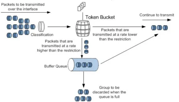
Figure 16: Traffic Shaping Using Token Bucket There are three types of Token Bucket Algorithm.
Single Rate, two color
In this algorithm there is only one bucket (Bc) to be filled that can hold limited amount of tokens. Traffic cannot exceed committed information rate (CIR) value.
Single Rate, three color
By this algorithm, new rate information is added called excess burst size (Be). In this type of algorithm, spilled tokens form Bc bucket which are exceeding the committed information rate, replenish the Be bucket. By the addition of Bc bucket, it is possible to support burstiness.
Dual Rate, three color
Dual rate bucket also has bursting feature. The only difference from the previous type is not to work with a single rate. It uses peak information rate (PIR). This new PIR is above the CIR value and makes it possible to burst. In Leaky Bucket Algorithm, average rate of data flow is regulated. It is token independent, does not save tokens. Packets are transmitted continuously at a constant rate.
According to formula of Leaky Bucket;
M = Maximum size of burst T = Emission interval
τ = Maximum Jitter Tolerance
δ = Time taken to receive and transmit a packet
How Leaky bucket works (Figure 17): Parameters: rate
1. Smooth out traffic by passing packets only when there is a token. Does not permit burstiness.
2. Discards packets for which no tokens are available (no concept of queue) 3. Application: Traffic shaping or traffic policing.
Figure 17: (a) Leaky Bucket with Water, (b) Leaky Bucket with Packets
4.2.2 Proposed Algorithm: Dual Token Bucket
Dual Token Bucket algorithm is used in out model. The dual rate with two token buckets has a bursting feature but it works differently compared to the other token bucket algorithms. Dual rate means that we don’t work with a single rate but we have a CIR (Committed Information Rate) and PIR (Peak Information Rate). This new PIR is above the CIR and allows us to burst.
Packets that are under the CIR value are called conforming.
Packets that are exceeding the CIR value and are also below the PIR are
called exceeding.
As can be seen in the figure below (Figure 18)
1. Tokens are replenished into the token buckets.
2. When a packet arrives, the algorithm will check if there are enough tokens in the bucket to allow the packet to get through.
Figure 18: Dual Token Bucket Algorithm
The reason why we used Dual Token Bucket algorithm is the bursting feature. Dual Token Bucket allows us to burst traffic without a duration limit. It is ideal for threshold based traffic management as can be seen in the example below:
4.2.3 Traffic Shaping
Traffic shaping is a method that adjust traffic output rate. While policing traffic, GGSN caches packets that exeed the traffic specifications then sends cached packets when there are enough token in the bucket to ensure service requirements.
Service Flow
1- GGSN identifies the type of service according to Layer 3/Layer 4 filters, Layer 7 protocol type, or Layer 7 protocol characteristics.
2- GGSN matches service control rules coming from PCRF.
3- GGSN shapes service traffic according to the matched service control rules. Detailed flow chart is given in the figure 20.
4.3 Implementation of Dynamic Bandwidth Allocation and Traffic Shaping
Dynamic bandwidth allocation is a technique to allocate bandwidth in a shared medium fairly on demand between subscribers. This is a type of managing available bandwidth. All subscribers in a network are not connected at same time, even if they’re connected; all of them are not transmitting data over network. Besides, some users need more bandwidth according to application they are using. For example, VoIP users or users that are watching video on internet should get more bandwidth than the users that are using P2P services.
The idea of assigning available bandwidth fairly to subscribers also depends on shaping their traffic. To optimize a traffic or guarantee performance (improving latency, increasing the usable bandwidth) you need to classify traffic, according to this classification traffic shaping and policing should be applied to the traffic of subscribers.
4.3.1 General Architecture in Basic
UPCC comprises two main parts, Backend (BE) and Frontend (FE). Provisioning Gateway (PGW) and Physical DB is located in BE. Policy Control and Rule Function is located in FE side. A service can be assigned to the subscriber over SOAP interface by provisioning system. This service can include bandwidth update or notification message.
4.3.2 QoS Policy Control Logic
PCRF has a QoS policy control logic as shown below:
Figure 22: QoS Policy Control
Policies include a trigger and rules. According to defined state of connection rules are selected if condition matches and action under the rule is sent to Policy and Charging Rule Function (PCEF, GGSN).
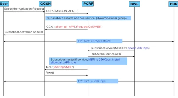
Signaling process in this policy enforcement can be seen with the following figures: Sending 256Kbps of E2E QoS to the subscriber:
At first, in PDP activation request, GGSN sends a Credit Control Request - Initial (CCR-I) to the PCRF and in the response coming from PCRF (Credit Control Answer – Initial, CCA-I) gets allow all default service. Then, service includes E2E QoS value of 256 Kbps is provisioned from provisioning system (BWL) and Policy and Charging Rule Function (PCRF) sends a Re-Auth Request (RAR) to the PCEF (GGSN) side. After that QoS is applied along the network and GGSN replied RAR message with a Re-Auth Answer that contains diameter success (2001) message.
In signaling process below, subscriber has a 256kbps of bandwidth then 7.2 Mbps QoS is provisioned to customer. Bandwidth is extended to 7.2 Mbps with a Re-Auth message.
Figure 24: 7.2Mbps Bandwidth Allocation Signaling
In this case, subscriber has 7.2 Mbps of bandwidth and a policy that limits bandwidth to 128 Kbps within a time interval. When the defined time is reached, system automatically sends the removal rule of limit_128k service so, E2E QoS becomes 7.2 Mbps again.
4.3.3 General Policy Control Logic of Facebook service
PCRF has a service policy control logic as shown in the example below:
Service is triggered according to logic explained in previous topic. Besides them, a quota manager is added. After assigned service quota is finished, PCRF can limit the usage of this service. This logic is like given below:
Figure 26: Facebook Rule Logic
As can be seen in the figure below, facebook service is provisioned from BWL. Then, subscriber can use facebook service, till the end of its quota. In this case, GGSN is reporting the usage amount of facebook service and PCRF is holding the remaining quota information according to updates coming from GGSN. After quota is exhausted, PCRF sends an RAR message to GGSN to remove the defined facebook rule and install the new rule limits facebook usage.
This quota amount can also be renewed when quota cycle resets or given time interval is reached. PCRF removes limitation rule and install Facebook rule again automatically with a Re-Auth message flow.
Chapter 5
SOAP and WEB SERVICES
5.1 Web Services
Web Service is a technology that communicates two devices over a network. A Web service is a software system designed to support interoperable machine-to-machine interaction over a network. It has an interface described in a machine-processable format (specifically WSDL).[11] It is developed as a solution to insufficient connection between devices that allows software systems to exchange data over internet or intranet. It’s useful because it can be used to provide data exchange softwares even they’re built in different languages. Web services can use XML for data exchange.
Figure 29: Web Service System[12]
Service Requester: Service requester is a system that request data. It finds and calls
required parameters related how to call web service.
Service Provider: Service provider enables requester to access services. Software
system is processing the request and provide the data.
Service Registry: It stores web service definitions about how to call each service.
Service providers publish and enables them to be provided when needed.
5.2 Advantages of Using Web Services
Web services operates platform independent and also can work in all platforms and implement easily. A web service written in Python language and operating on Linux server platform can be called by a Windows terminal. It provides efficiency in time and cost. It is using HTTP thus information communication does not interrupt by security systems (through designated port mechanism). [13] Since HTTP requests are
generally permitted to communicate over firewall. We can be sure that software programs that are using SOAP can communicate with other programs anywhere.
5.3 WSDL (Web Services Description Language)
WSDL is a standard XML format for describing network services. WSDL definition describes how to access a web service and operations will be performed. WSDL is used in combination of SOAP and XML scheme for providing web services over internet or intranet. Every special data types are defined in a WSDL file in XML format. Client can use SOAP to call functions listed in WSDL. It is developed by Microsoft and IBM. [14]
5.4 SOAP (Simple Object Access Protocol)
The Simple Object Access Protocol provides a simple and lightweight mechanism for exchanging structured and typed information between peer ends in a decentralized, distributed environment in which extensible markup language (XML) is used.Simple Object Access Protocol is a type for establishing communication between programs that are written in different languages and operating in different OS by using Hyper-Text Transfer Protocol (HTTP) and Extensible Markup Language (XML) for exchanging data.
It is a standard defined by W3C. XML is a standard used by web services to serve data. WSDL (Web Service Description Language), identifies the interface of the web service serves. WSDL describes the return types and parameters of functions existing in the web service. With the help of Discovery Protocol all web services in a server are organized. UDDI standards enable web services’ organization on web. Web service to web service sender and receiver mode is like in the figure below:
Figure 30: Web service to Web service in sender-receiver mode
SOAP consists of four parts:
SOAP envelope: It defines an overall framework, which determines what are
contained in messages, who can process the contents and whether the contents are optional or mandatory.
Remote procedure call (SOAP RPC): It defines a convention that represents
remote procedure call and response.
SOAP binding: It defines a convention in which SOAP envelopes are exchanged
between nodes through underlying protocols.
5.5 REST (REpresentational State Transfer)
Rest architecture is based on client-server communication. The services that are using this architecture called RESTful services. [17]
Platform free Language free Operates on HTTP
Flexible and can be extended.
RESTful Interface for Application QoS
Representational State Transfer (REST) is an architectural style that is based on widely used protocols and standards such as HTTP, URI, XML, and HTML.
In 2G, 3G, or 4G mobile networks, the RESTful Interface for Application QoS allows the PCRF to provide fast access for RESTful third-party application functions (AFs) by simplifying access. This helps guarantee resources for services initiated from third-party AFs. For example, when a subscriber uses an audio, video, or conference service provided by the AF, the PCRF needs to provide QoS guarantee demanded by the AF to ensure subscriber's service experience over Rx interface. [19] The AF can use simple HTTP for fast access to the PCRF.
5.6 REST and SOAP Advantages of REST
Lightweight and easily extendable.
Input and output data is so small considering SOAP.
Easy to design and implement, there is no need an extra tool. Works on HTTP.
Advantages of SOAP
Easy to consume comes with a scheme. Type-free, no need validations.
Has many development tools.
Security implementations are easier than REST.
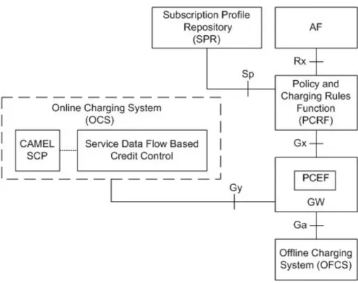
5.7 Service Provisioning (Gx SOAP Operations)
The subscription profile repository (SPR) provides the Extensible Markup Language (XML)/Simple Object Access Protocol (SOAP) interface, with which carriers can provide subscriber data management interfaces for the provisioning system, and realize secondary development.
Chapter 6
Deep Packet Inspection (DPI)
6.1 What is DPI
Deep packet inspection (DPI) is a method of filtering packets in network. In OSI (Open System Interconnection) layer, it works at application layer. It examines the header and data part of a packet. Packets are inspected according to defined criterias.
DPI makes it possible to find, identify, classify and block packets. By this features, Service providers can allocate available resources. For example, a packet that signed with high importance can be reached ahead according to low priority packet. It can also used be used for throttling data transfer abusive traffic according to demand on network to improve network performance of subscribers.
DPI can be used for multiple purposes. But the most popular usage in MBB networks is traffic shaping to manage congestion. Because congestion management protocols that used in end to end networks are insufficient. Growth in MBB networks is almost doubling in every year. And enhancement in the technology is not the cure for this amount of growth. [16]
The statistical amount of growth in MBB networks is given in below figures:
Figure 33:Mobile Data Growth[21]
Figure 34:Number of Smart Phone and Tablet Owners by Year
According to given graphs, there is no possible solution for congestion in the network other than policy based DPI. As can be seen in scenario below;
Applying traffic management and sharing resource between all subscribers is a solution but not affordable to fulfill subscriber requirements. Because all subscribers need different bandwidth amounts according to their usage. Like the difference between subscribers who are using streaming and instant messaging. It is impossible to watch a video without interruptions in case of a fixed bandwidth sharing and same for message delivery, there will be delay. Deploying a deep packet inspection based traffic shaping method to adjust
allocation of available bandwidth. This will allow subscribers to use application prioritized and can improve Quality of Experience (QoE).
6.2 End-to-End Internet
In early design of internet, it just cares sending data packets from sender to the receiver. It does not care what is inside of a packet. Even in early design, it does not check end side received or not. In today’s network applications and their usage are evolved. Packet loss issues, network address translation (NAT), filtering viruses, in short securing internet and allocating bandwidth on demand according to application type got more and more important. [15] They changed the architecture of internet. That’s why we need to investigate inside of packages by moving more intelligence to network.
The only way two end-points can obtain a completely reliable transfer is by transmitting and acknowledging a checksum for the entire data stream; in such a setting, lesser checksum and acknowledgement (ACK/NACK) protocols are justified only for the purpose of optimizing performance - they are useful to the vast majority of clients, but are not enough to fulfil the reliability requirement of this particular application. Thorough checksum is hence done at the end-points, and the network maintains a relatively low level of complexity and reasonable performance for all clients.
6.3 DPI Functions
Deep packet inspection can operate between Layer 2 and Layer 7 of the OSI model. In this process packet header and data part of the packet are inspected. Implementation of DPI has both hardware and software.
DPI needs a great amount of processing while inspecting inside of all packets. Besides, performance is very important. Traffic conditions shouldn’t be affected much. Software based approaches are good to filter packets. They’re easy to implement, flexible and cost effective. Because of the performance issues they need to use a dedicated hardware to reach realistic traffic rates.[20]
Dangerous traffic that is directed to subscribers can be identified and blocked In a shared network media, ISPs can use traffic more effective with
bandwidth on demand functions. And also unwanted traffic can be blocked. It is also used in governmental monitoring purposes of the internet.
The first DPI methods are developed for network security. Traditional firewalls located in local network were only checking the application and its port. But in this approach port 80 was always open for http and other applications can also use this port to send data. For example, web services use this http port to send datas over http packets. It was impossible to block this kind of traffic by port blocking. That’s why all packets going through a media should be inspected to understand its kind and applying a filter.
Bandwidth management is also an important function. Resources are limited and in any shared system users can encounter congestion problems. In today’s networks, amount of bandwidth hungry applicaitons are increasing. Instant video messaging, video presence (requires 10 Mbps), High definition television (requires between 5 and 8 Mbps), Real-time data backup (requires 2Mbps and 10 miliseconds of latency) are a few examples of these bandwidth hungry applications. Due to these bandwidth consumer applications there will be bottleneck in network. Even if one or two subscriber is consuming large amount of available bandwidth.
In mobile broadband networks logic, bandwidth is shared in last mile. Because of the limitation of frequencies. [2]
By the way, file sharing or messaging programs are always running in background. Normal TCP/IP congestion methods are not useful to find a solution for sharing total bandwith to subscribers fairly. The only solution is applying bandwidth management. Deep packet inspection is the only solution for detecting this kind of traffic and limiting bandwidth allocated for this application.
Figure 35:DPI, Old & New Approaches
Curent DPI platforms can be seperated into two categories: - General purpose packet processing platforms
This architecture uses blade servers to apply traffic shaping. Load balancing, special packet routing and processing can be handled in these nodes. This kind of servers are using CPU cores for deep packet inspection and packet shaping.
- Dedicated purpose packet processing platforms (ASICs or FPGAs)
This architecture is more common in DPI technologies. Because it can be optimised to run on a specific issue. These equipments are integrated to GGSN. GGSN is not a network element designed for packet inspection but with an integrated ciscuit it can handle this issue successfully.
Figure 36:DPI in OSI Layers
6.3.1 Shallow Packet Inspection (SPI)
SPI analyzes source and destination IP addresses, source and destination ports and protocol type at Layer 3 and 4 to identify information about network traffic. A traditional IP router also performs traffic identification and QoS guarantee to some extent by using the same information. A traditional IP router, however, analyzes only the contents below layer 4 in the IP header and identifies applications based on TCP/UDP port numbers.
6.3.2 Service Awareness (SA)
SA, in contrast of SPI, SA focuses on L7 (application layer) parsing in addition to L3/4 packet parsing. SA involves protocol identification, packet characteristic identification, and associated identification.
Packet Characteristic Identification
- Identification of known protocols, such as FTP, HTTP, DNS, and SMTP. With standards, special messages, commands, and state transition
mechanisms, these protocols can be identified accurately and reliably through an analysis of these special fields at the application layer.
Associated Identification
Network applications like VoIP, P2P and FTP that are used for voice, video and file transfer are using dynamically negotiated ports. If only port
identification is used, there is no way to identify data part of this communication. The traffic needs to be marked with its type.
6.4 Encryption: The Death of DPI?
In first phases of this project Facebook and twitter was allowing http connections then they changed their mind to encrypt its content. Now, it is optional to choose content encrypted or plain according to customer. And encryption is a big problem for Deep Packet Inspection. Also for VOIP and tethering issues, it is more complex to identify packets. Does this mean the end of DPI technologies? Actually, it was not. By these kind of changes in technology, signature based DPI developed. Increase in Facebook and Twitter usage was enormous as can be seen in the following figure and it is still a need to identify their traffic flow to manage network.
6.4.1 Heuristic Analysis (H-SA)
H-SA is for complex and encrypted protocol to be identified. Some protocols have no characteristic or encrypted for protocol identification. No difference can be seen between encrypted packages. But every application has a behavior while sending packets over network. By analyzing the behavior of packets over its port range, packet length, packet sending interval and frequency, identifying applications using P2P, VoIP and FTP protocols is possible.
Chapter 7
Testbed and Test Results
7.1 TC1 – Allocate 256K of Bandwidth to Subscriber
In this test case, 256Kbps of bandwidth and traffic THP 3 is assigned to subscriber and FTP data transfer is done to test available E2E bandwidth. To separate FTP traffic from the remaining traffic we applied a wireshark filter ftp || ftp-data as can be seen below. Then, the traffic rate is measured according to E2E QoS strategy assigned from PCRF (Network Controlled QoS). Avarage speed of FTP data transfer is limited to 256Kbps as seen in figure 7.1 and 7.1.1.
Wireshark Filter: Filters to detect ftp signaling and data traffic, ftp || ftp-data
IO Graph:
Avg Speed:
Figure 41: AVG Speed Graph of 256K of Bandwidth(E2E)
7.2 TC2 – Limit Bandwidth to 256K with Traffic Shaping
In this test case, traffic is limited to 256Kbps in a different way. Dual Token Bucket algorithm is applied in this case to limit traffic rate. Same filters are applied in wireshark. When I/O graph is examined in figure 7.2, there were oscillations at the beginning of file transfer then traffic is stabilized.
bwm-controller hw_uc5_bwm_control_down_256k car cir 128 cbs 24000 pir 256 pbs 48000 green pass yellow pass red drop
In the configuration given above, traffic is limited to 256Kbps (Peak information rate, PIR) but guaranteed to 128Kbps (Committed information rate, CIR). Committed burst size specifies the depth of first token bucket and it can be calculated according to this formula cir-value(kbit/s)*1000/8*1.5s. Peak burst size specifies the depth of second token bucket and can be calculated with this formula
pir-value(kbit/s)*1000/8*1.5s. 3 Color algorithm is used in this formula. Red stands for
violating and it is used for dropping packets, yellow stands for exceeding packets and the action used for this color is sending packet to a queue to be transmitted according to network conditions. In case of congestion, yellow marked packets are dropped. And the color green stands for conforming packets and the default action for this packets are pass.
Bandwidth: Limited to 256K
IO Graph:
Figure 42: IO Graph of 256K of Bandwidth Limiting(Traffic Shaping)
Avg Speed:
7.3 TC3 – URL Based Bandwidth Management (Unlimited and Limited Facebook Service)
In this test case, Facebook service is subscribed with E2E QoS of 42 Mbps. While using Facebook service, even if the limit service is applied to the subscriber, user will be connecting Facebook with 42Mbps as seen in figure 7.3. The difference between legacy bandwidth assignment and new bandwidth limitation can be seen with this test case. Now, it is possible to assign URL based QoS to the subscriber. Also it is possible to limit Facebook service speed (figure 7.3.2) and other applications will be able to connect with the speed of E2E QoS.
Bandwidth: Unlimited (General network E2E QoS 42Mbit) with unlimited and
limited Facebook service
Wireshark Filters: To filter Facebook related traffic source and destination IPs are
filtered for both limited and unlimited traffic.
Unlimited : (ip.src ==213.43.251.184 && ip.dst == 31.13.91.117) || (ip.dst ==213.43.251.184 && ip.src == 31.13.91.117)
IO Graph:
Avg Speed:
Figure 45: AVG Speed Graph of Facebook without Limitation
Limited: (ip.src ==213.43.251.187 && ip.dst == 31.13.91.117) || (ip.dst ==213.43.251.187 && ip.src == 31.13.91.117)
IO Graph:
Figure 46: IO Graph of URL Based QoS (Limited Facebook)
Avg Speed:
![Figure 2: Network Elements and Interfaces in MBB Networks [24]](https://thumb-eu.123doks.com/thumbv2/9libnet/4316559.70519/22.892.201.754.381.664/figure-network-elements-interfaces-mbb-networks.webp)


![Figure 19: Differences between Single and Dual Rate Token Bucket [28]](https://thumb-eu.123doks.com/thumbv2/9libnet/4316559.70519/41.892.212.721.776.1076/figure-differences-single-dual-rate-token-bucket.webp)