SOLAR POWERED HYBRID MULTILEVEL INVERTER
FED INDUCTION MOTOR USING FUZZY
PROPORTIONAL INTEGRAL SPEED CONTROLLER
by
Mehmet Akif SENOL*
Department of Electrical and Electronics Engineering, Faculty of Engineering and Architecture, Istanbul Gelisim University, Istanbul, Turkey
Original scienti ic paper https://doi.org/10.2298/TSCI180909052S
In this paper, speed control of solar powered single phase hybrid multilevel invert-er fed induction motor using fuzzy proportional integral controllinvert-er is proposed. The proposed control system has been developed using MATLAB/SIMULINK. Per-formance of the proposed controller is tested in reference speed conditions with step change. The parameter analyzed for the proposed controller is steady-state error and settling time. This is compared with the proportional integral controller. Proposed speed controller is tested with two speed region such as low speed region and high speed region. In low speed region, speed command is varied from 40, 60, and 80 rad/s with 0.6 s step time. In high speed region, speed command is varied from 100, 120, and 140 rad/s with 0.6 s step time. Corresponding, performance pa-rameters are measured and analyzed for both regions with proposed controller and proportional integral controller. From the test results, fuzzy proportional integral speed controlled hybrid multilevel inverter fed induction motor outperforms than proportional integral controller. Finally, the results are verified experimentally.
Key words: fuzzy-proportional integral controller, multilevel inverter,
solar power, steady-state error
Introduction
The conventional sources such as coal, diesel, gas etc., are depleting day by day. The cost of renewable energy technologies is getting down as energy production increases and the study of various alternate sources have gained momentum. Among the renewable sources, photovoltaic (PV) generation is important as it offers advantages such as low fuel costs, less pollutant, minimum maintenance and no noise. Applications of PV have been widely employed for power generation, satellite power system, solar vehicle and solar battery charging stations [1, 2]. In this paper, solar powered hybrid multilevel inverter (HMLI) fed induction motor using Fuzzy proportional integral (PI) speed controller is proposed. Solar PV array is non-linear in nature and the output power of the solar PV system depends on irradiation and temperature [3]. To extract the maximum power in solar PV system, incremental conductance maximum power point tracking algorithm is presented in this paper.
Normally, single phase H-bridge inverter is used to drive the induction motor when supply is direct current source but conventional inverter has some disadvantages such as har-monic level is high and noise effect is also high when driving induction motor. In order to over-Authorʼs e-mail: [email protected]
come this problem, multilevel inverter has been developed. Multilevel inverter produces a high level output whose waveform resembles a pure sinusoidal waveform due to that harmonic level is reduced and noise level also reduced but it is also has some disadvantages such number level is depends on switching device i. e., high level of output requires large number of switching devices. This will lead to power loss in switching device and also controlling technique is more complex. To solve this problem, HMLI has been developed as it requires only less number of switches for high level of output [4].
Speed regulation is the most important control parameter of induction motor. Conven-tionally, PI controller has been widely used in industries and controlling the target system. But it have some disadvantages such as constant parameter of the PI controller and manual tuning of parameter which leads to poor response in target system and may lead to unstable conditions. PI controller has been optimized by different optimization algorithm such as genetic algorithm, particle swarm optimization, etc. These algorithms tune the parameter of the PI controller in offline mode. In offline mode, large number of iteration and trial have to perform for obtain the optimal solution and also this is time consuming process [5]. In order to overcome this problem in this paper, online tuning or automatic tuning of parameter of the PI controller is proposed using fuzzy controller. Fuzzy controller automatically tunes the parameter of the PI controller based operating conditions of the induction motor. Fuzzy controller has the following advantag-es such as it doadvantag-es not need any mathematical model of the system, and human expert knowledge can be easily included in the fuzzy system using if then rules.
Solar powered hybrid multilevel inverter fed induction motor using fuzzy PI speed controller
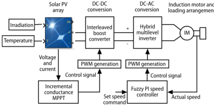
The proposed system consist of solar PV, maximum power point tracking controller, DC-DC converter, single phase HMLI, fuzzy PI speed controller, and single phase induction motor. The overall proposed system is shown in fig. 1.
Figure 1. Solar powered HMLI fed induction motor using fuzzy PI speed controller
Solar PV
array conversionDC-DC conversionDC-AC loading arrangementInduction motor and
Incremental conductance MPPT Voltage and current Irradiation Temperature Set speed
command Actual speed
IM Interleaved boost converter Hybrid multilevel inverter Fuzzy PI speed controller PWM generation PWM generation Control signal Control signal
In the proposed system, solar PV array output is processed via interleaved boost con-verter (IBC) with incremental conductance maximum power point tracking (MPPT) algorithm. Input for the MPPT controller is voltage and current of the solar panel and output of the MPPT controller is PWM pulse for IBC to extract maximum power from solar panel. The output of the IBC is fed to HMLI and it drives the single phase induction motor. The actual speed of the induction motor is sensed and compared with set speed command then speed error and rate of
change of speed error is processed via fuzzy PI speed controller and output of the controller is control signal and this processed via PWM generation unit for generating pulses to hybrid multilevel inverter for controlling the speed of the induction motor.
Solar PV array
Solar PV array module consists of series and parallel string of PV cell. The series string is used to sum up the voltage level of each PV cell and parallel string is used to sum up power level of each PV cell. The equation for single PV cell is expressed by eq. (1):
exp d 1 d o T V I I V = − (1) cell T kT V nl N q = ⋅ ⋅ (2)
where Id [A] is diode current, Vd [V] – the diode voltage, Io [A] – the diode saturation current,
nl – the diode ideality factor, k – the Boltzman constant, q – the electron charge, T – [K] the cell
temperature, and Ncell – the number of cells in series in array.
The single PV module having the following characteristics, the open circuit voltage, Voc is
36.3 V, maximum power point voltage, VmP is 29 V, short circuit current, Isc is 7.84 A, maximum power
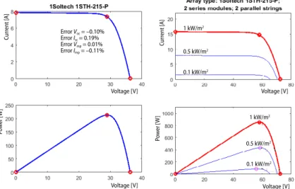
point current, ImP is 7.35 A, maximum power is 213.5 W, Ncell is 60, light generated current is 7.8649 A, saturation current is 2.95 e–10 A, ideality factor is 0.98117, shunt resistance is 313.39 Ω and series resistance is 0.3983 Ω. The I-V and P-V characteristics of single PV array are shown in fig. 2.
Voltage [V] Curr en t [ A] Voltage [V] Voltage [V] Po w er [ W ] Voltage [V] Po w er [ W ] Curr en t [ A] Error Voc = –0.10% Error Isc = 0.19% Error Vmp = 0.01% Error Imp = –0.11% 1 kW/m2 0.5 kW/m2 0.1 kW/m2 1 kW/m2 0.5 kW/m2 0.1 kW/m2
Figure 2. The I-V and P-V characteristics of single solar PV array and ten series and two parallel strings of solar PV array
In this paper, two series string and two parallel strings are used and corresponding I-V and P-V characteristics of solar array with different irradiation level is shown in fig. 2.
Incremental conductance maximum power point tracking algorithm
In incremental conductance method, solar PV array voltage is modified based on max-imum power point voltage. This method is based on the instantaneous and incremental conduc-tance of the solar PV array [6].
Basic idea of incremental conductance MPPT is shown in fig. 3. At maximum power point, the slope of the P-V curve is zero. Slope is increasing on left side of the P-V curve and decreasing on right of the P-V curve. The basic of incremental conductance method expressed by eqs. (3)-(5),
at maximum power point of the curve d
dVI = −VI (3)
at left of the maximum power point of the curve d
dVI〉 −VI (4)
at right of the maximum power point of the curve d
dVI 〈−VI (5)
where I and V are solar PV array current and voltage, respectively. Equation (4) represents the incremental conductance of the PV array and the eq. (5) represents the instantaneous con-ductance of the PV array. At maximum power point, rate of output conductance is equal to negative output conductance of the solar ar-ray. The MPPT generates the PWM control signal for IBC converter until the condition: ∂I/∂V = –I/V are satisfied. Flowchart for in-cremental conductance maximum power point tracking is shown in fig. 4.
Interleaved boost converter
The DC-DC boost converters are employed as interfacing circuit for the PV array with MPPT control to provide maximum power to the load [7]. Boost DC-DC converter have high power density, easy structure, quick transient response and constant input current and hence, this topol-ogy is used in different high power application such as power factor im-provement, PV energy conversion systems and electric vehicles. To supply high voltage output, DC-DC boost converter requires to be driven at maximum duty cycle which sub-jects the switching devices to small pulse, high magnitude current which leads to electromagnetic interference problems and reverse recovery and also reduces the dynamic response for load and line variations. A high V
P
Vmax
Pmax
Maximum power point
Left Right = 0 dP dV > 0 dP dV dVdP< 0
Figure 3. Basic idea of incremental conductance maximum power point tracking
Figure 4. Flowchart for incremental conductance maximum power point tracking
Start Sampling of PV array
current and voltage dV = V(k) – V(k – 1) dI = I(k) – I(k – 1) dV = 0 Yes No > − dI I dV V = − dI I dV V Yes Yes No No Yes No Yes No dI = 0 dI > 0 Vout = Vmax Iout = Imax D = D – ∆D D = D – ∆D D = D + ∆D D = D + ∆D End Next iteration
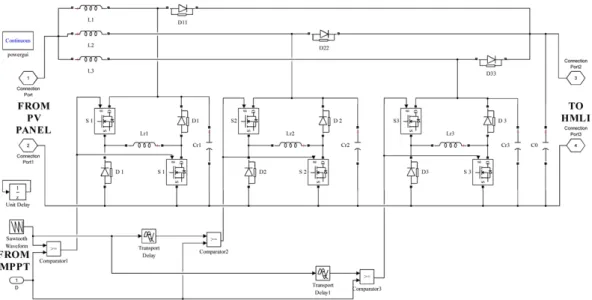
voltage output, small switching voltage loss without maximum duty cycle can be achieved us-ing converters with coupled inductor circuits. However, the efficiency of the converter reduces due to energy loss (leakage current) in the coupled inductor. To alleviate these problems and to increase the efficiency of the boost DC-DC converter, interleaving method is used [8]. Also, interleaving results in reduction of current through the input capacitors and enhances ripple current cancellation in the output capacitor. Further, it provides improved transient response and reduced EMI. In this paper, three stage interleaved soft switched boost converter is used for maximum power conversion converter. The simulink model of the three stages IBC is shown in fig. 5.
The designed values of IBC converter as follows, inductor (L1, L2, and L3) is 13.3 mH, (Lr1, Lr2, and Lr3) is 33.3 mH capacitor (Cr1, Cr2, and Cr3) is 100 µF, capacitor (C0) is 200 µF.
Figure 5. Simulink model of IBC converter
Hybrid multilevel inverter
Generally, H-bridge inverter is used to drives the single phase induction motor but in this paper, HMLI is used for driving the induction motor. This inverter has six switching devic-es to produce seven level output due to that output voltage looks like near sinusoidal and total harmonic distortion is less than 5% (IEEE-519 standard). Multiple references with inverted sine carrier PWM switching are employed for hybrid multilevel inverter to produce seven levels at output [9]. The simulink model of HMLI is shown in fig. 6. Multiple references with inverted sine carrier PWM switching logic is shown in fig. 7.
The output voltage of hybrid multilevel inverter for modulation index 0.9 is shown in fig. 8.
Fuzzy PI speed controller
The structure of fuzzy PI speed controller is shown in fig. 9 and in order to obtain the variable gain, fuzzy logic is employed for tuning the controller gain in online mode under all
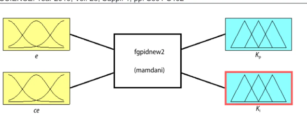
operating conditions. Fuzzy logic controller modeled by Mamdani fuzzy inference system [10]. The structure of fuzzy logic controller (fgpidnew2) is shown in fig. 10. It has two in-puts i. e., speed error, e, and the rate of change of speed error, ∆e, and two outputs, KP and KI. Each input has distributed with five bell shaped membership functions and each output has
distributed with five Gaussian norms membership functions.
Figure 6. Simulink model of hybrid multilevel inverter
Figure 7. The PWM pulse pattern for multiple references with inverted sine carrier PWM
Figure 9. Fuzzy PI speed controller Error KP KI d/dt Rate of change of error
Fuzzy logic controller
Control signal Speed error
KP
KI
Figure 8. Output voltage of hybrid multilevel inverter for modulation index is 0.9
Distribution of input membership function is shown in fig. 11. The universal bell shaped membership function is expressed:
2 1 ( ; , , ) 1 b f x a b c x c a = − + (6) The universal bell shaped function has three parameters. They are a, b, and c, where
a denotes the half width, b controls the slopes at the intersecting points, and c determines the
centre of the corresponding membership function. The input range for speed error is from 0 to 150, range of rate of change of speed error is from –150 to 150 and five membership functions denoted by positive-big (PB), positive-small (PS), zero (Z), negative-small (NS), and nega-tive-big (NB).
Figure 10. Proposed structure of fuzzy logic controller
e ce fgpidnew2 (mamdani) Kp Ki
Figure 11. Distribution of input membership functions for speed error and their rate of change
Input variable e
NB NS ZZ PS PB NB NS ZZ PS PB
Input variable ce
Each output is distributed with five Gaussian norms membership functions. The mem-bership functions are shown in fig. 12. The generalized Gaussian function expressed:
(
)
2 2 2 ( : , ) x c f x σ c e σ − − = (7)Figure 12. Distribution of output membership functions for proportional gain and integral gain
Output variable Kp Output variable KI
where c and σ gives the center and width of the membership function. Five Gaussian member-ship functions are expressed by small (S), medium (M), big (B), very big (VB), and very-very big (VVB). The range of proportional gain is from 0 to 5. The integral gain ranges from –1 to 1. There are totally 25 rules for fuzzy online gain tuner and few rules are described in eq. (8):
rule 1: if is NB and is NB then ( is VVB) ( is VVB) rule 25: is is PB and is PB then ( is S) ( is S)
p i p i e e K K e e K K ∆ ∆ (8)
In tab. 1., the overall rule base for fuzzy online gain tuner is shown. The fuzzy system uses the centroid defuzzification method. Centroid defuzzification gives the center of area un-der the curve. This is the most commonly used technique. It is described:
KpandKi ( ) Gain ( ) d d A x x A x x µ µ =
∫
∫
(9)Table 1. Rule base of fuzzy logic controller
Speed error
Rate of change of speed error
Speed error
Rate of change of speed error
KP NB NS Z PS PB KI NB NS Z PS PB NB VB VB VVB VB B NB VB VVB B B B NS VB VB VVB VB B NS VB VB VVB B M Z VVB VVB PB PS PS Z PB M S S S PS B M M M M PS M B M S S PB M M S M S PB M S S PS PS
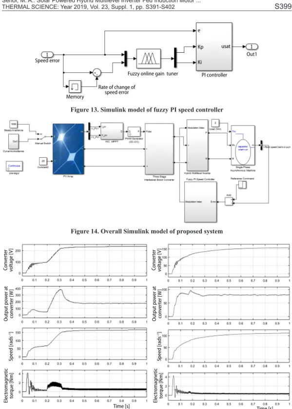
The output of the fuzzy logic controller gain is then multiplied with proportional and integral controller and it gives the control signal to the system. The simulink model of this controller is shown in fig. 13. The overall system is created and simulated in MATLAB/SIM-ULINK toolbox and simulink model of proposed system shown in fig. 14.
Simulation results and discussions
In this section, developed simulink model is tested for varying solar irradiation level. During this test, modulation index of the hybrid multi level inverter is maintain at 0.9 i. e., mo-tor is operated at open loop. Speed control of induction momo-tor is tested for two operating regions such as low speed and high speed with proposed controller and compared with PI controller. During this test, solar irradiation is maintained at constant irradiation level at 1000 W/m2. Constant irradiation level of solar PV array
In this section, solar PV array is operated with constant irradiation of 1000 W/m2, and
500 W/m2. The following results are obtained for analysis such as maximum power tracking,
speed of the induction motor, and electromagnetic torque of the motor. From the fig. 15, for irradiation level of 1000 W/m2, power output of the converter is 190 W, converter voltage is
230 V and speed of the motor is 170 rad/s. at irradiance level 500 W/m2, power output of the
converter is 86 W, converter voltage is 150 V and speed of the motor is 110 rad/s. From these results, if irradiation level changes, the corresponding voltage also chan ges and hence the speed of the motor varies.
Speed error
Memory
Rate of change of speed error
Fuzzy online gain tuner PI controller
Ki
Kp usat
Out1 e
Figure 13. Simulink model of fuzzy PI speed controller
Figure 14. Overall Simulink model of proposed system
Figure 15. Simulation results for irradiation level 1000 W/m2 and 500 W/m2, respectively
Time [s] Time [s] Speed [r ads –1] Con ver ter voltage [ V] O utput po w er a t con ver ter [ W ] Elec tr omag netic tor que [N m] Speed [r ads –1] Con ver ter voltage [ V] O utput po w er a t con ver ter [ W ] Elec tr omag netic tor que [N m]
Dynamic irradiation level of solar PV array
In this section, solar PV array is op-erated with dynamic change in irradi-ation level such as irradiirradi-ation level is changed randomly at 1 second interval and corresponding results are obtained for analysis. From the fig. 16, irradia-tion level is changed from 1000 W/m2 to
600 W/m2 then 600 W/m2 to 400W/m2
then 400 W/m2 to 1000 W/m2. In this
condition, converter output voltage and power is decreased and increased due to decreasing and increasing irradiation level. The speed of the motor is de-creased by decreasing irradiation level and speed is increased by increasing ir-radiation level.
Speed control of induction motor in low speed region
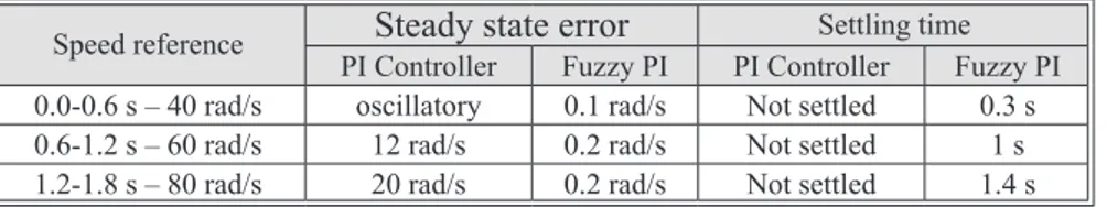
In this section, effectiveness of the fuzzy PI speed controller is examined with conventional PI speed controller at low speed region. The set speed command of the con-troller is varied from 40, 60, and 80 rad/s with 0.6 s step time. Load demand is maintained at 2 Nm. The corresponding speed responses are obtained for analysis.
From fig. 17 and tab. 2, it is observed that PI speed controller produces oscillatory response at set speed command of 40 rad/s and not settled at reference speed. At reference speed command 60 and 80 rad/s, PI speed is not settled and it has steady state error of around 12 to 20 rad/s. While analyzing the performance of the fuzzy PI speed controller, it does not produce oscillation in the speed response but a reduced steady state error of around 0.1 to 0.2 rad/s is obtained and it settles quickly.
Figure 16. Simulation results for dynamic change in irradiation level Time [s] Speed [r ads –1] Con ver ter v oltage [ V] O utput po w er a t c on ver ter W ] Elec tr omag netic t or que [N m] 1000 W/m2 600 W/m2 400 W/m2 1000 W/m2
Figure 17. Simulation results for low speed region and high speed region, respectively Time [s] Speed [r ads –1] Time [s] Speed [r ads –1] PI controller
Fuzzy PI PI controllerFuzzy PI Fuzzy PI controller Fuzzy PI controller PI controller PI controller
Speed control of induction motor in high speed region
In this section, effectiveness of the fuzzy PI speed controller is examined with con-ventional PI speed controller at high speed region. The set speed command of the controller is varied from 100, 120, and 140 rad/s with 0.6 s step time. Load demand is maintained at 2 Nm. The corresponding speed responses are obtained for analysis.
From the fig. 17 and tab. 3, PI speed controller has steady state error around 15 rad/s to 20 rad/s and does not track the set speed command but fuzzy PI speed controller has less steady state error around 0.2 rad/s to 0.3 rad/s and settling time of less than 2 seconds.
Table 2. Performance parameter for low speed region
Speed reference Steady state error Settling time PI Controller Fuzzy PI PI Controller Fuzzy PI 0.0-0.6 s – 40 rad/s oscillatory 0.1 rad/s Not settled 0.3 s 0.6-1.2 s – 60 rad/s 12 rad/s 0.2 rad/s Not settled 1 s 1.2-1.8 s – 80 rad/s 20 rad/s 0.2 rad/s Not settled 1.4 s
Table 3. Performance parameter for high speed region
Speed reference PI ControllerSteady state errorFuzzy PI PI ControllerSettling timeFuzzy PI 0.0-0.6 s – 100 rad/s 15 rad/s 0.2 rad/s Not settled 0.4 s 0.6-1.2 s – 120 rad/s 20 rad/s 0.3 rad/s Not settled 1 s 1.2-1.8 s – 140 rad/s 21 rad/s 0.2 rad/s Not settled 1.5 s
Experimental verification of proposed system
In this section, experimental set-up of the proposed system is presented. Hardware has been fabricated and tested in laboratory and the observed wave-form was recorded. The main power cir-cuit consists of three phase soft switched IBC and 2 SPM IGBT model (FSBB-20CH60B). To implement the MPPT and fuzzy PI control model, VHDL code is generated from MATLAB/SIM-ULINK model and FPGA chip is de-veloped in the Xilinx ISE 9.2i software environment, provided by Xilinx for analysis and synthesis of VHDL designs. The IGBT gate pulses are generated by using FPGA Spartan 3A kit with MPPT and Fuzzy PI control algorithm. Figure 18 shows shows the pulse for HMLI and Seven level output voltage of the HMLI
Conclusion
This paper has presented the speed regulation of hybrid multilevel inverter fed induc-tion motor using fuzzy PI speed controller. The overall system has been designed and simulated in MATLAB/SIMULINK toolbox. The system under study is tested with constant irradiance level and dynamic irradiance level and corresponding results are obtained and analyzed. From this analysis, speed of the induction motor is increased with increasing irradiance level and decreased with decreasing irradiance level. Moreover, proposed controller is tested for different operating conditions of the induction motor and compared with PI controller. From the test results, all vital parameters such as steady-state error and settling time are in favor for proposed controller. Therefore fuzzy PI speed controller is suitable for speed controller for induction motor drive. The hardware also successfully implemented without any deviation from the sim-ulation.
References
[1] Fazelpour, F., et al., Feasibility Study of Renewable Energy Resources and Optimization of Electrical Hybrid Energy Systems: Case Study for Islamic Azad University, South Tehran Branch, Iran, Thermal
Science, 21 (2017), 1A, pp. 335-351
[2] Ioakimidis, C. S., et al., Solar Thermal and Wind Energy Applications: Case Study of a Small Spanish Village, Thermal Science, 22 (2018), 5, pp. 2163-2176
[3] Mukti, R, J., Islam, A., Modeling and Performance Analysis of PV Module with Maximum Power Point Tracking in Matlab/Simulink, Applied Solar Energy, 51 (2015), 4, pp. 245-252
[4] Seyezhai, R., Mathur, B. L., Modeling and Control of a PEM Fuel Cell Based Hybrid Multilevel Inverter,
International Journal of Hydrogen Energy, 36 (2011), 22, pp. 15029-15043
[5] Premkumar, K., Manikandan, B. V., Bat Algorithm Optimized Fuzzy PD Based Speed Controller For Brushless Direct Current Motor, Engineering Science and Technology an International Journal, 19 (2016), 2, pp. 818-840
[6] Putri, R. I., et. al., Maximum Power Point Tracking for Photovoltaic Using Incremental Conductance Method, Energy Procedia, 68 (2015), Apr., pp. 22-30
[7] Seyezhai, R., Mathur, B. L., Design Consideration of Interleaved Boost Converter for Fuel Cell Systems,
International Journal of Advanced Engineering Sciences & Technologies, 7 (2011), 2, pp. 323-329
[8] Seyezhai, R., Mathur, B. L., Design And Implementation Of Interleaved Boost Converter For Fuel Cell Systems, International Journal of Hydrogen Energy, 37 (2012), 4, pp. 3897-3903
[9] Krishna, T. M., Kumar, C. B., A New Hybrid Multi Level Inverter to Improve the Performance of Induc-tion Motor, InternaInduc-tional Conference on ComputaInduc-tion of Power Energy, Proceedings, InformaInduc-tion and Communication (ICCPEIC), Chennai, India, 2015, pp. 0264-0268
[10] Premkumar, K., Manikandan, B. V., Fuzzy PID Supervised Online ANFIS Based Speed Controller For Brushless DC Motor, Neurocomputing, 157 (2015), June, pp. 76-90
Paper submitted: September 9, 2018 Paper revised: November 28, 2018 Paper accepted: January 10, 2019
© 2019 Society of Thermal Engineers of Serbia Published by the Vinča Institute of Nuclear Sciences, Belgrade, Serbia. This is an open access article distributed under the CC BY-NC-ND 4.0 terms and conditions

![Figure 16. Simulation results for dynamic change in irradiation level Time [s]Speed [rads–1]Converter voltage [V]Output power at converter W]Electromagnetic torque [Nm]1000 W/m2600 W/m2400 W/m2 1000 W/m 2](https://thumb-eu.123doks.com/thumbv2/9libnet/3606673.20759/10.892.151.469.220.612/figure-simulation-results-irradiation-converter-output-converter-electromagnetic.webp)