IEEE TRANSACTIONS ON PARALLEL AND DISTRIBUTED SYSTEMS, VOL. 6, NO. 6, JUNE 1995 561
Efficient Fast Hartley Transform Algorithms
for Hypercube-Connected Multicomputers
Cevdet Aykanat and Argun Dervig
Abstract- Although fast Hartley transform (FHT) provides efficient spectral analysis of real discrete signals, the literature that addresses the parallelization of FHT is extremely rare. FHT is a real transformation and does not necessitate any complex arithmetics. On the other hand, FHT algorithm has an irregular computational structure which makes efficient parallelization harder. In this paper, we propose a efficient restructuring for the sequential FHT algorithm which brings regularity and symmetry to the computational structure of the FHT. Then, we propose an efficient parallel FHT algorithm for medium-to-coarse grain hypercube multicomputers by introducing a dynamic mapping scheme for the restructured FHT. The proposed parallel algo- rithm achieves perfect load-balance, minimizes both the number and volume of concurrent communications, allows only nearest- neighbor communications and achieves in-place computation and communication. The proposed algorithm is implemented on a 32- node iPSC12' hypercube multicomputer. High-efficiency values are obtained even for small size FHT problems.
Index Terms-Digital signal processing, fast Hartley trans- form, parallel computing, multicomputer, hypercube, load bal- ance, nearest-neighbor communication.
I. INTRODUCTION
ZGZTAL signal processing (DSP) of real-time signals
D
has gained importance with recent advances in digital computer technology. Digital signal processors, digital com- puters specializing in signal processing, are in development and available on the market. All of this growth is for mas- sive amounts of computations in various DSP applications. One way to satisfy the performance requirement of DSP applications is to choose clever algorithms or expand the processor performance or both of them. DSP applications are characterized by computations that are massive but fairly straightforward and simple. Furthermore, these computations exhibit orderly structures. Besides, DSP algorithms are very efficient. These algorithms are optimized and improved several times until now. However, it is still not enough for most of the DSP applications. Performance of conventional computers are still very limited in cases where extensive number crunching computations are required. discrete Fourier transform (DFT) and discrete Hartley transform (DHT) are such examples.Manuscript received June 25, 1993; revised July 18, 1994. This work was supported by Intel Supercomputer Systems Division under Grant SSD100791-2 and the Turkish Scientific and Technical Research Council under Grant EEEAG-5.
The authors are with the Department of Computer Engineering, Bilkent University, 06533 Bilkent, Ankara, Turkey.
IEEE Log Number 9409879.
iPSCR is a registered trademark of Intel Corporation.
The DFT of an input sequence { f ( i ) : i = 0 , 1 , .
. . ,
N - 1)of length N is
N-1
for IC = 0,1,
. . . ,
N - 1. D F I provides a method for spectral analysis of discrete signals. Thus, Cooley and Tukey providing a more efficient algorithm [3], named as fast Fourier trans- form (FFT), made possible many applications concerning the computation of DFT to be realizable because of performance problems.Beyond the highly accepted usage of
FFT,
it is a complex transformation. That is, both DFT and FFT include complex arithmetic even if the input signal consists of real numbers only. Hence, FFT contains redundancy if the signals in the time domain are real. DHT is developed for a more efficient and faster transformation [4]. The DHT of an input sequence { h ( i ) : i = 0 , 1 , .. . ,
N - l} of length N isfor IC = 0 , 1 , .
. . ,
N - 1 where the input sequence h ( ) is constrained to real numbers only. Hartley transform does notnecessitate any complex arithmetics. This important feature of Hartley transform increases the performance of DHT by
a factor of two, while decreasing the memory requirements again by a factor of two at the same time. Computational complexities of both schemes are O ( N 2 ) . FFT reduces this time to O ( N l g , N ) [3]. As well as FFT, DHT has also a fast formulation called fast Hartley transform (FHT) [ 11, [2] with
computational complexity O ( N lg,N). FHT provides efficient
spectral analysis of real discrete signals.
The purpose of this paper is to investigate the efficient par- allelization of one-dimensional FHT algorithms on medium- to-coarse grain multicomputers implementing the hypercube interconnection topology. Computational load balance and communication overhead are two crucial factors that determine the efficiency of a parallel algorithm. In a multicomputer with high communication latency (start-up time), both the number and the volume of communications should be mini- mized in order to reduce the communication overhead. The communication structure of the parallel algorithm is also
a crucial issue. In a multicomputer, each adjacent pair of processors can concurrently communicate with each other over 1045-9219/95$04.00 0 1995 IEEE
562 IEEE TRANSACTIONS ON PARALLEL AND DISTRIBUTED SYSTEMS, VOL. 6, NO. 6, JUNE 1995 the communication links connecting them. Such communica-
tions are referred as single-hop communications. However, nonadjacent processors can communicate with each other by means of software or hardware routing. Such commu- nications are referred as multihop communications. Multi- hop communications are usually routed in a static manner over the shortest paths of links between the communicat- ing pairs of processors. In software routing, the cost of multihop communications is substantially greater than that of the single-hop messages since all intermediate processors on the path are intercepted during the communication. The performance difference between an individual multihop and single-hop communication is relatively small in hardware routing. However, a number of concurrent multihop commu- nications may congest the routing network thus resulting in substantial performance degradation. Hence, achieving con- current communications between adjacent pairs of processors is a valuable asset in designing efficient parallel algorithms. Moreover, in almost all commercially available multicom- puter architectures, interprocessor communications can only be initiated frodinto contiguous local memory locations. Hence, communications frodinto scattered memory locations may introduce considerable overhead to the parallel program. In this work, all these points are considered in designing an efficient parallel FHT algorithm for hypercube-connected multicomputers.
Although there is a substantial amount of literature on the parallelization of the
FFT,
the literature that addresses the parallelization of FHT is extremely rare. This situation can be attributed to the following reasons: 1) wide popularity of the FFT algorithm in the computer science literature, 2) irregular computational structure of FHT compared to the symmetrical and regular computational structure of the FFT, and 3) feasibility of indirect computation of FHT through FFT. However, direct computation of FHT is much more efficient compared to any indirect computation of FHT.To our knowledge, only Hou [6] and Lin [8] investigated the parallelization of FHT on hypercubes. Hou’s algorithm is a fine-grain algorithm which considers the parallelization of an N-point FHT on a hypercube with P = N processors, where each processor is assigned a single FHT point. In this work, we briefly describe an extension of Hou’s fine-grain algorithm to medium-to-coarse grain parallelism, where N 2
4 P . This algorithm uses only single-hop communications. The number and volume of concurrent communications required by this scheme are 3d
-
3 and x ( 3 d - 3)M FHT points, respectively, where M = N/P and d = 1gZP. The dynamic mapping scheme proposed by Lin [8] reduces the number of concurrent communications to d, each with a volume of NIP FHT points. Concurrent communication volume overhead of Lin’s algorithm is M d-
M/2 FHT points on the Hurtley graph. However, in a hypercube implementation of Lin’s algorithm, d - 2 concurrent exchange communication steps involve multihop communications since Hartley graph cannot be embedded with dilation-one onto the hypercube graph. Hence, concurrent communication volume overhead of Lin’s algorithm will be much higher on the hypercube topology due to the congestion during these d - 2 concurrent exchangecommunications. Although these two algorithms are successful attempts to reduce the communication overhead, neither of them achieves perfect load balance for the simplified butterfly scheme. Lin’s algorithm, which is originally proposed for the basic butterfly scheme, achieves perfect load balance only for this scheme. However, basic butterfly scheme requires ~ 6 0 % more floating point operations than the simplified butterfly scheme.
In this work, we propose an efficient restructuring for the sequential FHT algorithm which brings regularity and symmetry to the computational structure of the FHT. The restructured algorithm does not involve any computational overhead compared to the original algorithm. Then, we pro- pose an efficient parallel FHT algorithm for medium-to-coarse grain hypercube multicomputers by introducing a dynamic mapping scheme for the restructured FHT. The proposed parallel algorithm has the following nice features for the imple- mentation of an N-point FHT on a d-dimensional hypercube with P = 2d
5
N/4 processors: 1) achieves perfect load- balance for the simplified butterfly scheme, 2) allows only nearest-neighbor communications, 3) minimizes the number of concurrent communications to d by eliminating fragmentary message passing, 4) minimizes the total concurrent com- munication volume to dM/2 by minimizing the volume of communication in each concurrent exchange step to M / 2 = N / 2 P FHT points, and 5) achieves in-place computation and communication.The sequential FHT is presented in Section 11. In Section 111, parallelization of the presented FHT scheme is discussed. Section 111-A presents the proposed restructuring of the FHT algorithm for an efficient parallelization. The dynamic map- ping scheme proposed for the restructured FHT algorithm is presented in Section 111-B. Section IV presents the ex- perimental results on Intel’s iPSC/2 hypercube multicom- puter.
11. SEQUENTIAL FHT ALGORITHM
Different strategies exist for the computation of FHT and some include Radix-2 Decimation-in-Time FHT, Radix-2 Decimation-in-Frequency FHT, Radix-4 FHT, Split Radix FHT, Recursive FHT and Vector FHT [5], [7], [9], [lo].
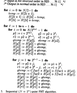
Computational steps for a 32 point, radix-2, decimation-in- time FHT algorithm [7] is illustrated in Fig. 1. This tabular representation is proposed in [lo]. The input in this scheme is N real numbers in bit-reversed order. The output is N real numbers in normal order. The
Ci
and Si factors in Fig. 1 represent Cos(27ri/N) and S i n ( 2 ~ i / N ) , respectively. As is seen in Fig. 1, each level of FHT algorithm takes a set of N real numbers and transforms them into another set of N real numbers. This process is repeated n = lg,N times, resulting in the in-place computation of the desired Hartley transform in normal order. However, the tabular representation is not sufficient for a detailed analysis of the computational interdependencies which is crucial for an efficient parallel algorithm design. In this work, computational flow graph for the FHT algorithm is derived in order to explore the computational interdependencies.AYKANAT AND DERVIS: FHT ALGORITHMS FOR HYPERCUBE-CONNECTED MULTICOMPUTERS 563
Fig. 1. Computational steps in ( N = 32)-point fast Hartley transform.
Ci = Cos(PxiM), Si = Sin(2dM)
(a) (b)
Fig. 2. butterflies.
Computational flow graphs for (a) type-1 and (b) type-2 basic FHT
A close examination of Fig. 1, reveals that FHT computa- tions at each level resemble basic
FFT
butterfly computations. The first level(t
= 0) consists of 2-point FFT-like butterflies. However, the remaining levels(t
= 1 , 2 , ..
',
n - 1) consistof 4-point FHT butterflies. There are two types of basic FHT butterflies which will be referred here as type-1 and type-2 basic FHT butterflies. Fig. 2 illustrates the computational flow graphs for type-1 and type-2 basic FHT butterflies at level in an N-point FHT. Each type of FHT butterfly is identified by an ordered 4-tuple {p, T , q, s}. Note that both types of basic butterflies consist of two stages.
In the first stage of a type-1 basic FHT butterfly, the ( q , s)
pair is involved in two butterfly type of computations to generate four intermediate results. Each butterfly computation involves the multiplication of q and s points by Cos/Sin and Sin/Cos factor pairs, respectively, and pairwise addition of
Stage-1 Stage-2
I
Stage-1 Stage-2I
Ci = Cos(Pm/N), Si = Sin(Pm/N) (a) (b) Fig. 3. FHT butterflies.Computatlonal flow graphs for (a) type1 and (b) type-2 simplified
these four multiplication results. Hence, the first stage of a type- 1 basic butterfly involves eight multiplications and four additions. In the first stage of a type-2 basic butterfly, both
q and s points are multiplied by Cos
+
Sin (CS) factor pairs to generate four intermediate results. Hence, the first stage of a type-2 basic butterfly involves four multiplications. In the second stages of both type-1 and type-2 basic butterflies, these four intermediate results are individually added to theirp, T , q, s points to update these values for the next level. The second stages of both types of basic FHT butterflies involve four additions.
A careful analysis of type- 1 basic butterfly computation reveals that angles of Cos and Sin factor pairs multiplied by the q and s points are mutually T radians away from each other, since 2 ~ ( i
+
% ) / N = 2 ~ i / N+
7r. Hence, type-1 basic FHT butterfly (Fig. 2(a)) can be simplified as shown in Fig. 3(a). This simplification reduces the total number of floating point%4 IEEE TRANSACTIONS ON PARALLEL AND DISTRIBUTED SYSTEMS, VOL. 6 , NO. 6 , JUNE 1995
operations in the first stages of type-1 butterflies to 6 (from eight multiplications and four additions to four multiplications and two additions) as follows:
qtemp := Ci x H [ q ]
+
Si x H [ s ] ; stemp := C j x H [ s ]+
S j x H [ q ] ; H [ q ] := H[p] - qtemp; H [ s ] := H[T] - sremp; H[p] :=Hb]
+
qtemp; H[T] := HIT]+
stemp; ( 3 4 (3b) (3c) ( 3 4 (3e) (30 The resulting FHT butterfly will be referred here as type-1simpZiJied FHT butterfly. A similar analysis can also be ap-
plied to type-2 basic FHT butterfly to reduce the number of multiplications involved in the first stage from four to two. Furthermore, a detailed analysis shows that Cos
+
Sin factors multiplied by the q and s points are always 1. Hence, the remaining two multiplications can also be omitted. Fig. 3(b) illustrates the computational flow-graph for a type-2 simplijiedFHT butterfly. Note that multiplications with Cos+ Sin factors are shown in Fig. 3(b) for the sake of completeness. Hence, the computations involved in a type-2 simplified FHT butterfly are as follows: qtemp := H [ q ] ; (4a) stemp := H [ s ] ; (4b) H [ q ] := H[p] - qtemp; (4c) H [ s ] := H[T] - sremp; ( 4 4 H[p] := Hlp]
+
qtemp; (4e) H [ r ] := H[T]+
sremp; (40 In the rest of the paper, simplified FHT butterflies will be re- ferred as butterflies for the sake of simplicity, unless otherwise stated.Each FHT point in an N-point FHT is assumed to have an n-bit binary representation where n = lg,N. For example, f n
(binary string of length n) denotes the binary representation of an FHT point q where q denotes its decimal index in the bit-reversed ordering. In both types of butterflies, FHT points in both ( p , q ) and (T, s) pairs differ only in the Cth bit of their n-bit binary representation at level C such that q = p
+
2e and s = T+
2e. That is, Cth bits of the binary representations ofboth q and s indexes are “1,” whereas lth bits of both p and T indexes are “0.” Note that the least significant bit of a binary number is referred here as its 0th bit. Hence, FHT points in
( p , q ) and (T,s) pairs are separated by 2e at level C.
In a type-1 butterfly at level C, two FHT points of each
( q , s ) pair differ only in the least significant bits of their n-bit binary representations. This difference is such that, least significant C bits of the binary representations of the q and s
indexes are mutually 2’s complement of each other. Hence, the separation between q and s indexes of a type-I butterfly varies between 2 and 2e - 2 at level l for C 2 2. In a type-2 butterfly at level C, q and s points only differ in the
(e-
1)th bit of their binary representations such that q is an odd multipleof 2e, and s = q
+
2e-1. That is, q and s indexes of a type-2 butterlly are separated by 2‘-’ at level C. Hence, type-2 butterflies at level C can easily be identified by the 4-tuples{ p , T, q , s} = { p , p
+
2e-1, p+
2‘, p+
3 x 2‘-l} where pis a multiple of 2e+1 (i.e., least significant (C
+
1)-bits are all 0’s). These observations can be summarized by the following definitions.Dejinition I : For any binary strings bk and fe-1
#
4e-1(where
IC
= n-
C - l ) , the 4-tupleconstitutes a type-1 FHT butterfly at level C (C = 2, .
. . ,
n - 1) in an ( N = 2”)-point FHT. Here, subscripts denote the lengths of the respective binary strings, 4e-1 denotes a string consisting of .! - 1 zeros, andfiFl
denotes (C - 1)-bit 2’scomplement of f e - 1 . Note that and (Oft-1) are C- bit 2’s complement of each other since f e - 1 contains at least one 1.
Dejnition 2: For any binary string b k (where IC = n-e-l), the 4-tuple
{brc00&-1, bkolcbe-1, b k l O 4 e - 1 , b k l l $ e - i }
constitutes a type-2 FHT butterfly at level C (C = 1 , 2 , .
.
.,
n -1) in an ( N = 2n)-point FHT.
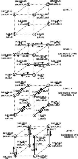
Fig. 4 illustrates the proposed computational flow-graph for the ( N = 32)-point FHT algorithm using the simplified butterfly scheme. As is seen in Fig. 4, first level
(e
= 0)is a special level which consists of two-point butterflies without any Cos/Sin factor multiplications. That is, only additiodsubtraction operations are performed in two-point butterflies. Each level C of the following n - 1 levels
consist of N/2e+1 consecutive blocks where each block contains 2e+1 consecutive FHT points. For example, at level C = 3, a 32 point FHT contains 32/23+1 = 2 blocks, Bg = (0
-
15) and BA = (16 - 31}, where each block consists of 23+1 = 16 consecutive FHT points.First, second, third, and fourth quarters of each block contain 2e-1 p , r , q and s points of the Ze-’ butterflies confined to that block. The first points of successive quarters of each block constitute the p , r , q , s points of the only type- 2 butterfly involved in that block. As is seen in Fig. 4,
{ 16, 20, 24, 28) is the only type-2 butterfly involved in block BA = (16 - 31}, whereas (17, 23, 25, 31}, (18, 22, 26, 30) and (19, 21, 27, 29) constitute the type-I butterflies in that block. Hence, the number of type-1 and type-2 butterflies at level C are
respectively. Note that N&
+
N& = N / 4 FHT butterflies exist at each level for C = 1 , 2 , .. . ,
n - 1. Also note thatlevel 1 = 1 consists of only N/4 type-2 butterflies and the
number of type-2 butterflies decreases by one half in the following n
-
2 levels and reduces to 1 at the last level (1 = n - 1).AYKANAT AND DERVIS: FHT ALGORITHMS FOR HYPERCUBE-CONNECTED MULTICOMPUTERS 565
LEVEL 0 LEVEL I LEVEL 2 LEVEL 3 LEVEL 4
Stage-I Stage-2 Stage-I Stage-2 Stage-I Stage-2 Stage-I Stage-2
CI = Cos(12dN) SI = Sin(12dN)
Fig 4 Computational flow graph for the 32-point FHT and its static tiled mapping on a three-dimensional hypercube
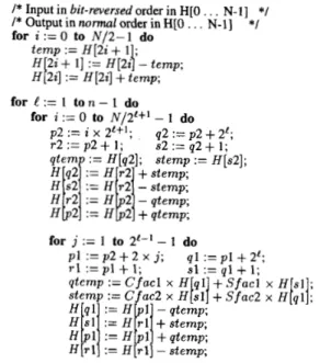
Fig. 5 illustrates the pseudo-code for the sequential FHT algorithm. In this algorithm, N real inputs { h ( i ) : i =
0,1, . .
. ,
N - l} are assumed to be stored in bit-reversed order in one-dimensional H-array. Computations are performed in- place and the results are obtained in the H-array in normalorder. As is seen in Fig. 5, the first outer for-loop performs the computations associated with the 2-point butterflies in the first level
(e
= 0). The second outer for-loop performs the computations associated with the remaining n - 1 levels. The first inner for-loop iterates N/2'+' times to identify the N/2'+' consecutive FHT blocks at each level. The innermostfor-loop iterates 2'-' - 1 times to identify and perform the computations involved in the 2'-' - 1 type-1 butterflies in each block. In Fig. 5, p l , r l , q l , s l and p 2 , r2, q2, s2 refer to the
p, r , q , s points of type-1 and type-2 butterflies, respectively. The total number of type-1 and type-2 FHT butterflies are
(6b) respectively. Recall that type- 1 and type-2 simplified butter- flies require 10 and 4 floating-point operations, respectively, and that first level
(e
= 0) involves only N floating point ad- ditiodsubtraction operations. Hence, the sequential execution time of an N-point FHT computation can be modeled as(7) N n-1 N$2 = - 1, e=i Tseq = (2.5Nlg2N - 4.5N
+
6)tcalc566 IEEE TRANSACTIONS ON PARALLEL AND DISTRIBUTED SYSTEMS, VOL. 6, NO. 6, JUNE 1995
/* Input in bit-reversed order in HIO
.
..
N-11 */ /* Output in normu1 order in HIO . . . N - l ] for i := 0 to N / 2 - 1 do t e m p := H [ 2 i + 1 ; H 2i+
11 := H [ 2 4 - t e m p ; */ := H [ 2 i ] + t e m p ; fore : =
1 t o n - 1 do for i := 0 to N / 2 f + 1-
1 do p 2 := i xP+l;
q2 := p 2+
21; r 2 := p 2+
2e-1; s2 := q2+
2 t - l ; qtemp := H[q2]; s t e m p := H [ s 2 ] ; for j := 1 to 2 f - 1 - 1 do p l := p2+
j; q l := pl+
2 5 r l := p 2+
2'-
j ; S I := r l+
2e;Fig. 5. Sequential ( N = 2")-point FHT algorithm.
where tcalc is the time taken by the floating-point multipli- cation, addition and subtraction operations. The computation of Cos/Sin factors are not involved in the given complexity analysis.
In most of the real time DSP applications, N-point FHT is applied consecutively, for a fixed N, to N-point input data sets. Hence, in general, N / 2 coefficient values are computed once, as the value of the N is fixed, and stored in a table. These coefficients are then accessed by a simple table-lookup procedure during successive FHT computations.
111. PARALLEL FHT ALGORITHM
There are strong computational dependencies in the FHT algorithm. These computational dependencies exist between successive levels confined within the butterflies. As is seen in Fig. 3(a) and Fig. 4, stage-2 computations in type- 1 butterflies depend on the results of the stage-1 computations. The compu- tation of qtemp and stemp values [(3a) and (3b), respectively] in the first stage necessitates bidirectional interdependency between q and s points, which will be referred here as
q ++ s interactions. Note that first stages of type-2 butterflies involve no computations and interactions. Type-2 butterflies are also modeled as two stage computations just for the sake of completeness. The update of p, r, q and s points in the second stages of all butterflies (for C = 1 , 2 , . .
. ,
n - 1) necessitatebidirectional interdependencies between the p and q , and r and s points, which will be referred here as p H q and
r H s interactions. The p w q and r H s interactions are
very regular in nature since p and q, and r and s points are separated by 2e at level C for C 2 1. In fact, this regularity in the p H q and r H s interactions makes hypercube topology very suitable for the parallelization of FHT. However, the
q tf s interactions complicates the parallelization because
of the irregular spacing between q and s points of type-1 butterflies.
This paper investigates the parallelization of ( N = 2")- point FHT on a d-dimensional hypercube with P = 2d processors, where the number of 4-point FHT butterflies is an integer (power of 2) multiple of the number of processors (i.e., N 2 4 P ) . A straightforward parallelization can be achieved by adopting a static tiled mapping. The first processor in the decimal ordering is assigned the first M = N/P FHT points, the second processor is assigned the next M points and so on. Successive processors in the decimal ordering are assigned the consecutive slices of FHT points with each slice containing equal number of M consecutive FHT points. This mapping prevents the fragmentation of FHT butterflies and (q, s) pairs during the first n - d and n - d
+
1 levels, respectively.Both (p, q ) and (r, s) pairs of butterflies are fragmented across processor pairs which are neighbors over channel c = C
-
n+ d at level C for C = n - d , . . .,
n - 1. Here, channel c denotes the set of P / 2 communication links between processor pairs whose d-bit binary representations differ only in their cth bit. Hence, these pairwise exchanges due to the p H q andr H s interactions can be accomplished by performing a
concurrent single-hop exchange communication over channel
c = C- n + d at level C for C = n- d,
. .
,
n-
1. Unfortunately, the nature of fragmentation of (4, s) pairs, and hence the nature of the communications due to the q H s interactions arevery irregular and complicated because of the irregularity in these interactions. A careful analysis reveals that the q H s
interactions necessitate concurrent exchange communications, each with a volume of M - 1 FHT points, at each level of the last d - 1 levels, plus concurrent exchange communications,
each with a volume of single FHT point, at each level of the last d - 2 levels. All former type of exchange communications are single-hop communications at level 1 = n - d
+
1 and multihop communications with distances 2,. . .
,
d - 1 during the last d - 2 levels C = n - d+
2, . . .,
n - 1, respectively. All latter type of communications are single-hop communications at level C = n - d+
2 and mostly multihop communicationswith maximum distances 2, . . .
,
d-2 during the last d-3 levelsC = n - d
+
3,. . . ,
n - 1, respectively. Multihop exchange communications during the last d - 2 levels will introduce drastic performance degradation due to the congestion.The fine-grain algorithm proposed by Hou [6] considers the parallelization of N-point FHT on a hypercube with P = N processors, where each processor is assigned a single FHT point. Here, we will briefly describe an extension of Hou's fine-grain algorithm to medium-to-coarse grain parallelism. A
tiled decomposition scheme is adopted for the initial mapping. This initial mapping is maintained during the first n - d
+
2 levels C = 0 , 1 , ..
.,
n - d+
1. The tiled mapping schemealready confines the FHT butterflies to 1-dimensional and 2- dimensional subcubes over channels c = 0 and c = 0 , l at levels C = n - d and C = n - d
+
1, respectively. Hence, the second stages of levels C = n-d and C = n - d + l , and the first stage of level C = n - d+
1 necessitate concurrent single-hop exchange communications over channels c = 0 , 1 and c = 0 due to the p H q , r H s and q H s interactions, respectively.AYKANAT AND DERVIS: FHT ALGORITHMS FOR HYPERCUBE-CONNECTED MULTICOMPUTERS 567 Then, at the end of each level C = n - d
+
l , . . . , n - 2,those processor pairs which exchanged their local M - 1 or M q or s points during the first stage of that level, exchange the further responsibilities of these local FHT points. These mapping exchange operations performed at the end of each level C, for C = n
-
d+
1,. . .
,
n - 2, confine the FHT butterflies to 2-dimensional subcubes over successive channels C - n+
d and C - n+
d+
1, at the following level C+
1. The d-bit binary representations of four processors in each subcube differ only in their cth and (c - 1)th bits such that these two successive bits are “00,” “01,” “lo,” and “11” in the first, second, third, and fourth processors, respectively. The fragmentation of FHT butterflies across these subcubes during the last d - 1 levels is such that first, second, third and fourth processors in each subcube hold M p, T , q and s points, respectively, of the M butterflies confined to that subcube. Hence, each level C of the last d - 1 levels require three concurrent single-hop exchange communications, each with a volume of A 4 (or M - 1) FHT points, over channels c- 1, c and c- 1, respectively, where c =C - n
+
d. The first and second exchange communications are information exchange operations due to the q H s, and p H q,T H s interactions in the first and second stage computations, respectively. The third exchange communication is a mapping exchange operation due to the nonlocal q H s swaps. Note
that level C = n - d necessitates only one concurrent single- hop exchange communication over channel c = 0, and the mapping exchange communication at the last level may not be necessary. Thus, the number and volume of concurrent communications required by this scheme are 3d - 3 and z ( 3 d - 3 ) M FHT points, respectively.
The dynamic mapping scheme proposed by Lin [8] reduces the number of concurrent communications to d. The initial mapping avoids the fragmentation of two-point butterflies at level C = 0 by assigning consecutive FHT-point pairs to successive processors in a cyclic manner. This initial mapping scheme can be considered as a scattered mapping of consec- utive FHT-point pairs, where FHT point pair (22, 22
+
1) is assigned to processor i mod P . The dynamic mapping during the following d levels confines the FHT butterflies to processor pairs which are neighbors on the Hartley graph during levelsC = 1 , 2 ,
. . .
,
d, and prevents the fragmentation of butterflies during the last n - d - 1 levels. At level C = 1 , 2 , . . . , d , processor pairs whose least significant C- 1 bits are all 0’s hold M / 2 type-2 butterflies, whereas all other processor pairs hold M / 2 type-1 butterflies. Former and latter types of processor pairs will be referred here as type-2 and type-1 processor pairs, respectively. The fragmentation of level4 butterflies (forC = 1 , 2 , . . . , d ) across each processor pair is such that ith local FHT-point pairs in the first and second processors, whose
(C - 1)th bits are 0 and 1, correspond to the ( p , ~ ) and ( s , q )
pairs of the butterflies, respectively, confined to that processor pair, for i = 0,1, . . .
,
M/2- 1. The first and second processors of type- 1 pairs are responsible for updating the (p, s ) and ( T , q)pairs, respectively, or vice-versa, depending on their Cth bits. The first and second processors of type-2 pairs are responsible for updating the ( p , q ) and ( T , s ) pairs, respectively. Hence, type-1 processor pairs need to exchange all of their local FHT points at the beginning of each level C = 2 , . . . , d .
However, type-2 processor pairs need to exchange only half of their local FHT points at the beginning of each level C =
1,2,
.
. .,
d. These exchanges will be referred here as type-1 and type-2 exchanges, respectively. One half of the M local FHT points involved in each type-1 exchange is a mapping exchange, whereas the other half is exchanged because of the computational interdependencies. Type-2 exchanges are both mapping and information exchanges.All P / 2 processor pairs are type-2 pairs at level 1 = 1, and the number of type-2 processor pairs decreases by one half in the following d - 1 levels, thus reducing to 1 at level C = d. Thus, the communication volume of type-1 exchanges determines the concurrent communication volume during levels C = 2,3,
. .
.,
d. Hence, concurrent communica- tion volume overhead of Lin’s algorithm is Md - M / 2 FHT points on Hartley graph. Unfortunately, Hartley graph cannot be embedded with dilation one onto the hypercube graph as is also indicated in [8]. In a hypercube implementation of Lin’salgorithm, type-2 exchanges are single-hop communications over channel c = C - 1 at level C for C = 1 , 2 , .
. . ,
d. Type-1 exchanges at level C = 2 are single-hop communications over channel c = 1. Hence, all exchanges can be concurrently performed over channels c = 0 and c = 1 at levels C =1 and C = 2, respectively. However, type-1 exchanges at levels C = 3,
. . . ,
d are mostly multihop communications with maximum distances of C - 1 = 2, . ..
,
d - 1. Hence, concurrent communication volume overhead of Lin’s algorithm will be much higher on the hypercube topology due to the congestion during these d - 2 levels.Although these two algorithms are successful attempts to reduce the communication overhead, neither of them achieves perfect load balance for the simplified butterfly scheme. Con- sider the coarse-grain extension of Hou’s algorithm. The tiled mapping scheme, which is maintained during the first n - d
+
2 levels, achieves perfect load balance during the first n - d levels, since it assigns equal number of unfragmented butterflies to each processor during these levels. However, load balance is disturbed during the first stage computations of the last d levels. At levels C = n - d and C = n - d+
1, . . .,
n - 1, processors can be considered as divided into 2 and 4 groups, each containing P / 2 and P / 4 processors, respectively. At level 1 = n - d, each processor in the first and second halves of the hypercube holds and updates M/2- 1 ( p , T ) and ( q , s ) pairs of type-1 butterflies, respectively. Hence, at level C = n - d, one half of the processors holding q and s points concurrently perform 3M - 6 floating point operations while the processors in the other half wait idle for receiving these qtemp andstemp results corresponding to the first stage computations of type-1 butterflies. At levels C = n - d
+
1,...
, n - 1, each processor in the first, second, third, and fourth quarters of the hypercube holds and updates either M - 1 or M p, T , q ands points of type- 1 butterflies, respectively. Hence, at levels
C = n - d
+
1, . . .,
n - 1, one half of the processors holdingq or s points concurrently perform 3M or 3M - 3 floating point operations while the processors in the other half wait idle for receiving these qtemp or stemp results corresponding to the first stage computations of type-1 butterflies. Note that this algorithm cannot achieve perfect load balance even for
568 IEEE TRANSACTIONS ON PARALLEL AND DISTRIBUTED SYSTEMS, VOL. 6. NO. 6, JUNE 1995
(a) (b) (C)
Fig. 6. Computational mappings of FHT butterflies to processors (a) coarse-grain extension ofHou's algorithm
(e
= n-d+l,. . . , n-1). (b) Lin's algorithm(e
= 1 , 2 , . . . , d ) , (c) proposed algorithm ( a = n - d , . . . , n - 1 ), during the respective levels which involve communications.the basic butterfly scheme during the first stage computations of last d
-
1 levels because of the four-way computational fragmentation of FHT butterflies during these levels. Here, four-way computational fragmentation refers to the situation in which four different processors compute the four different points of the same FHT butterfly.Lin's algorithm, which is originally proposed for the basic butterfly scheme, achieves perfect load balance only for this scheme. This algorithm achieves perfect load balance during levels l = 0 and C = d
+
1 ,. . . ,
n - 1 , both for the basic and simplified butterfly schemes, by assigning equal number of unfragmented butterflies to each processor during these n-
d levels. The 2-way fragmentation during levels4
= 1 , 2 ,.
..
,
d achieves perfect load balance for the basic butterfly scheme during these d levels. Consider the performance of this algorithm for the simplified butterfly scheme during d-
1levels C = 2,
. .
.,
d. After the exchange operations during these levels, M / 2 type-] butterflies are duplicated in each type-1 processor pair. However, each processor in type-1 pairs is responsible for updating either the ( p , s ) or ( T , q ) pairs of the respective M / 2 butterflies. Hence, both processors in each type-1 pair should compute the same qtemp and stempvalues for all M / 2 butterflies local to that processor pair, because these two values are needed in the second stage computations of both ( p , s) and ( T , q ) pairs. This redundancy during the first stage computations of type- 1 butterflies reduces the performance of the algorithm to that of the basic butterfly scheme. This redundancy can be avoided if the first and second processors in each type-] pair compute the qtemp and stemp
values, or vice-versa, and then exchange these results. This approach attains the performance of the simplified butterfly scheme with perfect load balance at the expense of d - 1 extra single-hop exchange communications each with a volume of M / 2 FHT points.
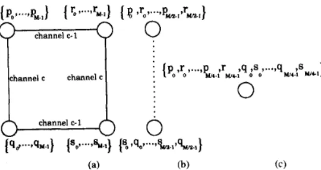
Fig. @a) and (b) clearly illustrate the four-way and two- way computational fragmentation of 4-point FHT butterflies in coarse-grain extension of Hou's algorithm and Lin's algo- rithm, respectively, during the indicated levels which involve communications. Note that the two-way fragmentation at level
e
= n-
d of the coarse-grain extension of Hou's algorithm is not shown in the figure since it is an exceptional level of this algorithm. In this figure, p,, r i , q, and s, represent the p ,T , q and s points of the same butterfly, respectively. Circles represent processors and solid lines indicate the adjacency of the respective processor pairs in the hypercube topology. The square represents a two-dimensional subcube over channels
c - 1 and c. Dashed line indicates the adjacency of the respective processor pair in the Hartley graph. The orderings in the lists indicate the local orderings of the FHT points in the H arrays of the respective processors.
In the following section, we propose and describe a restructuring which brings regularity to the q t-f s interactions, without disturbing the regularity of the p
*
q and T t-f sinteractions. Then, we will propose a dynamic mapping scheme for the restructured algorithm which totally avoids the computational fragmentation of FHT butterflies, as is illustrated in Fig. 6(c).
A. Restructuring
The computational interdependencies between the succes- sive levels of the FHT algorithm should be closely examined in order to achieve a suitable restructuring for an efficient parallelization. Two consecutive blocks Bzz and B,2"+' at level C constitute the block B;+, at the next level C
+
1, for z = 0, 1 , . . . , 2 n - e - 2 - 1 . For example, in a 32 point FHT (see Fig. 4), two consecutive FHT blocks Bz = ( 1 6-
2 3 )and B: = (24 - 3 1 ) at level
C
= 2 constitute the FHT block l?; = ( 1 6 - 3 1 ) at the next level C = 3 . The( l
+
1)th bits of the indexes of all FHT points in even and odd numbered blocks Be22 and Bit+' at levelC
are 0 and 1, respectively. We can deduce the following two theorems by considering the butterfly pairs ( T j E B i z , T,' Ewhere T,' - T: = 2e+1. Here, T i - T: = 2'+' denotes that,
p ; - p i = T i - T; = q: - 4: = si - s: = 2e+1 where T,' = { p i , T ; , qk, s i } and T: = {p,", reo, q;, sj}. That is, ( T j , T i ) denotes the set of 2'-l butterfly pairs in consecutive FHT blocks Bzz and Biz+1 at level
C
such that the indexes of the p , r , q and s points of the two butterflies in each pair differ only in their (C+
1)th bits. For example, in a 32-point FHT (see Fig. 4), (T: E B;, T i E B:) denotes two butterfly pairs ( ( 1 6 , 18, 20, 2 2 } , ( 2 4 , 26, 28, 3 0 ) ) and ((17, 19, 21, 2 3 } , (25, 27, 29, 3 1 ) ) .Theorem 1: Each level-l
(e
2
2). type-1 FHT butterfly pair(2'1: E B ~ ' , T l ~ E Biz+') constitutes the type-1 butterfly pair (FTle+l, S71e+l) E B;+l at the next level l
+
1, whereFTle+i = (pe+l,re+i,~e+i.se+i> F F F F = { ~ e , s e , p e ~ ~ e ) 0 0 1 1
s s s 0 0 1 1
S n + l = {PP+l, Te+1, 4e+1. $+l> = {re > 4e 1 Te > 4 e ) . Proofi Since T l : and T1: are type-] butterflies at level
e
m l e + i STle+i
and T1i - T1: = 2(+l, we have
p i = bk000fe-1 = bkooge; si = b k o l l
fi-l
= bkolg,"; p i = bk100fe-1 = bkl0ge; T ; = b k O O l fe'_l = bkoog," 4: = bk010fe-1 = b k o l g e T j = b k l O l f $ - , = bklog," Si = b k l l l f , " _ l = b k l l g g ; 4: = b k l l O f e - 1 = b k l l g e wherek
= n - C - 2. Here, ge = O f t - 1# 4 g ,
andg," =
# 44
since f e - 1#
4e-1
by Definition 1. Hence,0
proof follows by Definition 1.AYKANAT AND DERVIS: FHT ALGORITHMS FOR HYPERCUBE-CONNECTED MULTICOMPUTERS 569
0 stage-1 stage2 stage-1 *-2
T1 I
I
I
I
I
I
I
I
I
I
I
I
I
I n st--1 St-2 stagE-1 stage-2LEVEL- (L) LEVEL- (L+1) I LEVEL- (L) LEVEL- (L+1)
(a) (b)
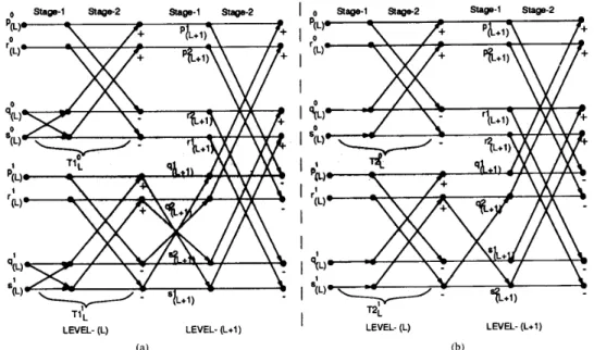
Fig. 7. The combination structures of (a) type-I, (b) type-2 FHT butterfly pairs.
Theorem 2: Each level-C (I 2 l ) , type-2 FHT butterfly
constitutes the butterfly pair
identify their decimal indexes in the H-array. For example, we will consider the combination structures of the butterfly pairs (T:,Ti) where
pair (T2; E Bzi, T2: E
(FDe+l,STle+l) E Bf+, at the next level
(e
+
l ) , whereFDe+i = {peF+l,reF+l, qeF+1, $+11 = {P:, &,p:, ~ m e + l =
{ ~ f + i ,
rf+i 7 &+I, $+1) = {re,
se,
re,
0 0 0 0
T,O = { ~ t , re, qe 1 s t } = {ill iZ,i3,i4}
q1
= { P i , r i , d , s i } = { j 1 , % 2 , j 3 , j 4 } .0 0 1
1
are type-2 and type- 1 butterllies, respectively. and T2:
-
T2; = 2'+l, we haveProof: Since T2: and T2: are type-2 butterflies at level
e
R2E+l STle+i p j = bkO004e-1 = bkOO4e = b k O O ( l 4 c - l ) q; = b k O l O q 5 - 1 = bkOlq5t s; = b k O l ( l q h c - 1 ) p: = bk1004e-1 = b k l O 4 e 4; = bkll04t-l = b k l l d e = b k l O ( l 4 e - 1 ) s j = bkll(14e-l)
where
k
= n - C - 2. Proof follows by Definitions 2 and 1since O4e-1 =
&
and !-bit 2's complement of (14e-1) is Fig. 7 illustrates the combination structures of type-1 and type-2 butterfly pairs. As is seen in Fig. 4, in a 32 point FHT, the type-1 butterfly pair ({ 1 , 7 , 9 , 1 5 } E B:, { 17,23,25,31} E B i ) at levele
= 3, constitutes the type-1 butterfly pair({1,15,17,31},{7,9,23,25}) E at the next level C = 4. Similarly, the type-2 butterlly pair ({0,4,8,12} E
B:,
{ 16,20,24,28} E BA) at level l = 3, constitute the (type-2, type-1) butterfly pair ({0,8,16,24}, {4,12,20,28}) E B: at the next levele
= 4.In the discussions given so far, p , r , q and s labels were used both to identify different points of FHT butterflies and the decimal indexes of the corresponding FHT points in the H - array. However, for the sake of clarity of further discussions,
p, r , y and s labels will be used only to identify different points of FHT butterflies, whereas i and j labels will be used to
equal to itself.
17
Note that i and j indexes satisfy the same relations previously defined for p , ~ , q and s points. That is, i 3 = i l
+
2e, 24 = i2+2',j3 = j l + P , j 4 =jz+2',j1-21 = j Z - i Z = j 3 - i 3 = j 4 - 24 = 2'+', . . ., etc. In this notation, Theorems 1 and 2 can be restated as follows: level-(e+
1) (FTlg+l, STle+l)and (FT2e+l, STle+l) pairs generated by type-1 (Tl;, T l i )
and type-2 (T2;, T2:) pairs will have the following structure in the H-array:
Rlk'+l = { i l > i 4 , j l , j 4 } STh+l {22ri3,j2,j3} m & + 1 = { i i , i 3 , j i , j 3 } STh+i = {i2,24,jz7j4},
respectively.
Theorems
1
and 2 reveal that regularly separated (by powers of 2's) butterfly pairs at a particular level constitute scrambled butterfly pairs at the following level. The scrambled combina- tion of the butterfly pairs is the main reason for the irregularspacing betyeen q and s points of type-1 butterflies in the following levels. However, this scrambling between butterfly pairs can be avoided by a clever re-ordering while storing the computational results of each butterfly into the H-array. This internal re-ordering will be different for type-1 and type-2 butterflies since the combination structures of these two types of butterfly pairs are different from each other. Combination structure of type-2 FHT butterfly pairs is also investigated since they generate a single type-1 butterfly at the following level.
570 IEEE TRANSACTIONS ON PARALLEL AND DISTRIBUTED SYSTEMS, VOL. 6, NO. 6 , JUNE 1995
Stager Stage-2 ALIGNMENT Stage-I Stage2
LEVEL- (L) (a) LEVEL- (L+1)
I
I
I
I
I
I
I
I
I
I
I
-0 Stage-I Stage-2 ALIGNMENT Stage-l Stage2
LEVEL- (L) LEVEL- (L+l) (b)
Fig. 8. The combination structures of (a) type-I, (b) type-2 restructured FHT butterfly pairs.
The scrambled combination of type- 1 butterfly pairs are avoided by swapping r and s points of type-1 butterflies while storing their updated values into the H-array. The scrambled combination of type-2 butterfly pairs are avoided by swapping r and q points of type-2 butterflies while storing their updated values into the H-array. In this scheme, the results of type-1
(Tl!, T1:) and type-2 (T2;, T2:) pairs will have the following order in the H-array at the completion of level-C computations;
respectively. Hence, in the proposed scheme, the generated type-1 ( F T l e + l , STle+l) and (type-2, type-1) (FT2e+l, STle+l) pairs will have the following structure in the H-array
according to Theorems 1 and 2, respectively. Fig. 8 illustrates the alignment operations during the computation of restruc- tured FHT butterflies, and the combination structures of the restructured butterfly pairs. The computations involved in a restructured type-1 simplified FHT butterfly are
qtemp :=
Ci
x H [ q ]+
Si x H [ s ] ; stemp := C j x H [ s ]+
S j x H [ q ] ; H [ q ] := H[p]-
qtemp; H [ s ] := H [ r ]+
stemp; H [ r ] := H [ r ]-
sremp; (8b) (8c) ( W(80
H[p] := H[p]+
qtemp;The computations involved in a restructured type-2 simplified
FHT butterfly are qremp := H [ q ] ; (9a) stemp := H [ s ] ; (9b) H [ q ] := H [ r ]
+
stemp; (9c) H [ s ] := H [ r ] - stemp; ( 9 4 H [ r ] := H[p] - qtemp; (9e) H[p] := H[p]+
qtemp; (90Comparison of (8) with (3), and (9) with (4) reveals that the proposed restructuring does not introduce any computational overhead. The proposed restructuring has the following nice features. The combination structures of both types of butterfly pairs are very similar. Consider both type-1 and type-2 level4 butterfly pairs (T:, 2):' that combine to constitute the
( F T e + l , STe+l) butterfly pairs at the next level
C
+
1. The first (last) two FHT points of T: followed by the first (last) two FHT points ofTl
will constitute FTe+l (STde+l) respectively, at the next level. The only difference is the reverse allocation of the FHT points of the ( p , r ) and ( q , s) pairs of the secondSTe+l butterfly in the H-array when ( T j , T i ) is a type-1 butterfly pair. Note that the proposed restructuring avoids the scrambled combination structure between butterfly pairs at successive levels. Furthermore, in the proposed scheme, p , r points and q , s points of both FTe+l and STe+l will be allocated to the consecutive locations of the H-array if p , r points and q , s points of both T; and T i are initially allocated to the consecutive locations of the H-array. This structure is valid for both types of butterfly pairs in the proposed restructuring scheme, since ( p , r ) and (9, s) pairs of
FTe+l and STe+l constitute the first two and last two points, respectively, of both types of T: and T i butterflies. That is, if
Tle" = { i l , 21
+
1,i3,23+
1) = { j i , j i+
l , j 3 , j 3+
1)AYKANAT AND DERVIS: F'HT ALGORITHMS FOR HYPERCUBE-CONNECTED MULTICOMPUTERS 571
LEVEL0 LEVEL1 ALIGN LEVEL2 ALIGN LEVEL3 ALIGN LEVEL4 ALIGN
0 18 1 31
m
30 5 27 4 28 9- -
23 P1 10 22 13 18 8 24 17- -
15 P2 18 14 21 11 m 12 25 L -7 P3 B 6 29 3 Cos(12dN) Cos(i2WN) + Sin(12dN)I Cob(~2xlN) + Sin(prJN) - = -
- -
x
=2iG:;z
VI CosWdN) Fig. 9.during the last two levels C = 3 and C = 4 correspond to mapping exchanges of the respective FHT points.
Computational flow graph for a 32-point restructured FHT and its tiled mapping on a two-dimensional hypercube. The nonlocal alignment operations
then we will have
Similarly, if
then we will have
This important feature of the proposed restructuring scheme will be exploited to avoid the fragmentation of the (4, s) pairs of type- 1 butterflies during the parallelization.
In the original FHT algorithm, 4-point butterfly computa- tions start at level
e
= 1 which contains only type-2 butterflies.Note that p , T points and q , s points of all type-2 butterflies
at level C = 1 are already allocated to the consecutive locations of the H-array. Hence, if the proposed restructuring is applied starting from level C = 1, then p , r points and
q , s points of all butterflies at the following levels will be allocated to the consecutive locations of the H-array. Fig. 9 illustrates the computational flow-graph for the restructured 32-point FHT algorithm. As is seen in Fig. 9, the type-1 butterfly pair ({ 18,19,22,23}, {26,27,30,31}) at level C = 2 constitutes the type-1 butterfly pair, ({18,19,26,27}, {23,22,31,30}) at the following level l = 3. Similarly, type-2
butterfly pair ({16,17,20,21}, {24,25,28,29}) atlevell = 2
constitutes the (type-2, type-1) butterfly pair ({ 16,17,24,25}, {20,21,28,29}) at the following level l = 3. As is also seen in Fig. 9, the proposed restructuring does not disturb the block structure of the original FHT algorithm. Furthermore, the proposed restructuring brings regularity and symmetry to the in-block allocation structure of the FHT butterflies. The following paragraph explains the regular allocation structure of 2e-1 = Ze+l/4 butterflies in each block at level
e
for572 IEEE TRANSACTIONS ON PARALLEL AND DISTRIBUTED SYSTEMS, VOL. 6, NO. 6, JUNE 1995
/* Input in bit-reversed order in HIO . .
.
N-I] *I/* Output in normal order in H[O
. . .
N-1] for i := 0 to N / 2 - 1 do t e m p := H [ 2 i+
1 ; H [ 2 i+ 11
:= H [ 2 4 - t e m p ; H[2i] := H [ 2 i ] + t e m p ; for i := 0 to N/2'+' - 1 do *I fore
:= I to 72 - 1 do p2 := i x 2;+'; r 2 := p 2+
1; qtemp := H[q2]; H q2 := H r 2+
stemp; H s2 := H r 2-
stemp; H r 2 := H 2 - qtemp; H 2 := H 2 + q t e m p ; for j := 1 to 2l-I - 1 do q2 := p 2+
2 f ; s 2 := q2+
1 ; s t e m p := H [ s 2 ] ; p l : = p 2 + 2 x j ; qI : = P I $ 2 ; ;ti
ci
Tl :=PI f 1; H [ r l ] := H [ r l ] - stemp;Fig. 10. Restructured sequential ( X = 2n)-point FHT algorithm.
In each block, 2'-l consecutive FHT-point pairs in the first and second halves constitute the ( p , r ) and ( q , s ) pairs, respectively, of the butterflies involved in that block. Con- secutive FHT-point pairs in each half are ordered regularly such that ith pairs in the first and second halves constitute the ( p , r ) and ( q , s) pairs of the same butterfly, respectively, for i = 0 , 1 , .
. .
,2'-l. The first pairs ( i = 0) in each half constitute the only type-2 butterfly involved in that block. The following - 1 consecutive pairs ( i = 1 , 2 , . . .,
P-'
- 1)in each half constitute (2'-l - 1) type-1 butterflies involved
in that block. However, the last (2e-2 - 1) consecutive pairs
( i = 2e-2
+
1,. .
. ,2'-' - 1) in each half hold the FHT pointsof ( p , r ) and ( q , s) pairs in the reverse order (i.e., as { r , p } and
{s, 4)). These reverse ordered ( p , T ) and ( q , s ) pairs belong to
the second type- 1 butterflies generated from type- 1 butterfly pairs in the previous level.
For example, in a 32-point restructured FHT algorithm (see Fig. 9), the 4-tuples { 0 , 1 , 8 , 9 } , { 2 , 3 , 1 0 , ll}, {4,5,12,13}, { 7,6,15,14} constitute the 23-1 = 4 FHT butterflies involved
in block B! = (0 - 15) at level C = 3. Note that the first
butterfly (0, 1 , 8 , 9 } is the only type-2 butterfly involved in
B!. Also note that ( p , r ) and ( q , s) pairs of only the last type-1 butterfly { 7,6,15,14} are hold in reverse order in the H-array
since 23-2 - 1 = 1. As is seen in Fig. 9, this type-1 butterfly is the second butterfly generated by the type-1 butterfly pair
( { 2 , 3 , 6 , 7 } , {10,11,14,15}) in the previous level
(e
= 2).Fig. 10 illustrates the pseudo-code for the restructured FHT algorithm. Note that this algorithm has a very similar structure compared to standard algorithm given in Fig. 5 since both programs exploit the block structure of the FHT computations at each level. However, the assignment statements for p , r, q , s
indexes are different due to the restructuring. Furthermore, (8)
and (9) are used instead of (3) and (4), respectively, in order to realize the internal alignment operations for the restructured
butterfly computations. The last 2e-2 - 1 iterations of the
innermost for-loop for C 2 3 need extra attention since FHT
points of the last (ZeP2 - 1) (p, r ) and ( q , s ) pairs of each block are hold in reverse order in the H-array during these levels. A careful analysis of (3) reveals the symmetry between the computations of p and r points, and q and s points of type-1 butterflies. That is, correct values for the type-1 butterflies will also be computed if we interchange p with r , q with s , and i
with j in (3). In this case, qtemp will hold the correct value of stemp and vice versa. This symmetry in type-1 butterfly computations is exploited in the restructured FHT algorithm as follows. The first two lines in the innermost for-loop computes the indexes of the p , r , q , s points of type-1 butterflies involved in a particular block assuming a proper ordering of the FHT points in ( p , r ) and ( q , s ) pairs. Hence, during the first 2e-2 iterations, p l , r l , q l , sl variables refer to the correct FHT points p , r , q , s, respectively, in the H-array. However, during the last 2e-2
-
1 iterations, p l , r l , q l , s l indexes refer to r , p , s, q points, respectively, in the H-array. Thus, this scheme implicitly achieves the interchange of p with r , and q with s.The interchange of the Cos/Sin factors (i.e., interchange of i and j ) is also achieved implicitly during construction of the Cos/Sin factor indgx tables prior to the execution of the program. As is seen in Fig. 9, at level C = 4, i / j indexes of the last 24-2 - 1 = 3 Cos/Sin factor pairs appear in reverse order (as j / i ; 9/7,10/6,13/3). Hence, the last four statements of the
innermost for-loop effectively computes the correct values for the s, p , r , q points of type-1 butterflies, and stores them into
H[ql], H[sl], H[pl], H[rl], respectively. Thus, the updated
values of the s , p , r, q points of type-1 butterflies are effectively stored into their s, q , r , p locations, respectively. Hence, p and
q points of type- 1 butterflies are effectively swapped, instead of r and s points, during these iterations.
The implementation scheme proposed in Fig. 10 modifies the combination structure of the last 2e-2 - 1 type-1 butterfly
pairs (Tl;, 7'1:) in each block pair (Biz, Bii+l), at levels
C
2
3. We need to examine the combination structure of these reverse butterfly pairs in order to show that the implementation scheme in Fig. 10 does not disturb the regularity and symmetry of the proposed restructuring. Consider the reverse type- 1 (Tl;, 7'1:) butterfly pairs, whereT1; = { i l
+
1 , i l , 23+
1,23} TI: = {ji+
1 , j i , j 3+
l,.b}.The algorithm in Fig. 10 effectively swaps p and q points of reverse type- 1 butterfly pairs during the alignment operation. Hence, reverse type- 1 butterfly pairs will have the following allocation structure:
= {ig
+
1,21,21+
1,23}= { j 3
+
l , j i , j i+
l , h }in the H-array just after the alignment operations. Thus, according to Theorem 1, type-1 ( F T l e + l , STle+l) pairs
generated by the reverse type-1 butterfly pairs will have the following structure:
R l e + i = {p;,s;,p:,s:} = (23
+
1,23,j3+
l , j 3 }0 0 1 1