3D HAIR DESIGN AND KEY FRAME
ANIMATION IN REAL TIME
A THESIS
SUBMITTED TO THE DEPARTMENT OF COMPUTER
ENGINEERING
AND THE INSTITUTE OF ENGINEERING AND
SCIENCE
OF B˙ILKENT UNIVERSITY
IN PARTIAL FULFILLMENT OF THE
REQUIREMENTS
FOR THE DEGREE OF
MASTER OF SCIENCE
By
Barkın Ba¸sarankut
July, 2008
I certify that I have read this thesis and that in my opinion it is fully adequate, in scope and in quality, as a thesis for the degree of Master of Science.
Prof. Dr. B¨ulent ¨Ozg¨u¸c (Supervisor)
I certify that I have read this thesis and that in my opinion it is fully adequate, in scope and in quality, as a thesis for the degree of Master of Science.
Asst. Prof. Dr. Tolga C¸ apın (Co-Supervisor)
I certify that I have read this thesis and that in my opinion it is fully adequate, in scope and in quality, as a thesis for the degree of Master of Science.
Assoc. Prof. Dr. Veysi ˙I¸sler
I certify that I have read this thesis and that in my opinion it is fully adequate, in scope and in quality, as a thesis for the degree of Master of Science.
Asst. Prof. Dr. H. Murat Karam¨uft¨uo˘glu
I certify that I have read this thesis and that in my opinion it is fully adequate, in scope and in quality, as a thesis for the degree of Master of Science.
Prof. Dr. ¨Ozg¨ur Ulusoy
iii
Approved for the Institute of Engineering and Science:
Prof. Dr. Mehmet Baray
ABSTRACT
3D HAIR DESIGN AND KEY FRAME ANIMATION IN
REAL TIME
Barkın Ba¸sarankut M.S. in Computer Engineering Supervisors: Prof. Dr. B¨ulent ¨Ozg¨u¸c and
Asst. Prof. Dr. Tolga C¸ apın July, 2008
Computer generated animations of humans, animals and all other kinds of objects have been studied extensively during the last two decades. The key for creating good animations has been to correctly imitate the behaviors of real objects and reflect these into computer generated images. With the rapid development of computer technology, creating realistic simulations has become possible, and the most striking components of these realistic animations happen to be the most dynamic (moving) parts; hair, in the case of human animations.
With the development of high quality hair animations, the concern is not only creating physically correct animations, but also controlling these animations. An implementation of a key frame hair animation creation system, supported by a hair design tool, helping to model and animate hair easily, and provide these functionalities in real time is the aim of the proposed system.
This work reviews several hair animation and sketching techniques, and pro-poses a system that provides a complete level of control (capable of controlling even the individual hair strands) of key frame animation and hair design in real time.
Keywords: hair simulation, sketching, key frame. iv
¨
OZET
3 BOYUTLU C
¸ ˙IZ˙IM ˙ILE GERC
¸ EK ZAMANLI SAC
¸
MODELLEMES˙I VE ANAHTAR KARELERLE
S˙IM ¨
ULASYON
Barkın Ba¸sarankut
Bilgisayar M¨uhendisli˘gi, Y¨uksek Lisans Tez Y¨oneticileri: Prof. Dr. B¨ulent ¨Ozg¨u¸c ve
Asst. Prof. Dr. Tolga C¸ apın Temmuz, 2008
Bilgisayar tabanlı animasyonlar (insanlar, di˘ger canlılar ve her t¨url¨u nesneler) uzun seneler boyu ¨uzerinde ara¸stırma yapılmı¸s konulardır. Bu animasyonların ba¸sarıya ula¸smasında en ¨onemli rol, nesnelerin hareketlerinin do˘gru ¸sekilde taklit edilebilmesi olmu¸stur. Bilgisayar teknolojisinde ya¸sanan hızlı ilerlemeler sonucu, son derece ger¸cek¸ci animasyonlar ¨uretilmeye ba¸slanmı¸stır. Animasyonlarda en ¸cok dikkat ¸ceken ¨o˘gelerse, tahmin edilebilece˘gi gibi en hareketli b¨olgelerdir. Bu hareketli ¨o˘geler insan ve y¨uz animasyonlarında genellikle sa¸clardır.
Y¨uksek kaliteli animasyonların yapılmasında, sadece fiziksel ger¸cek¸ci harekete ve g¨or¨unt¨uye sahip animasyonlar yapmaktan ziyade, bu animasyonları ger¸cek za-manlı olarak kontrol edebilme gereksinimi de olu¸smu¸stur. Bu tezde tartı¸sılacak sistem, y¨uksek kalitede bir animasyonun sıfırdan olu¸sturulup, anahtar kareler kullanılarak hareketlendirme problemine bir ¸c¨oz¨um ¨onermektedir. Sa¸cın ger¸cek zamanlı olarak tasarlanıp, anahtar kareler aracılı˘gıyla animasyonu ama¸clanmaktadır.
Bu ¸calı¸smada daha ¨once sa¸c animasyonu ile ilgili yapılmı¸s di˘ger sistemlerden bahsedilecek ve s¨oz konusu sistemler dı¸sında nasıl bir ¸sekilde bu animasyonların olu¸sturabilece˘gine dair ¸c¨oz¨umler getirilecektir.
Anahtar s¨ozc¨ukler : sa¸c sim¨ulasyonu, ¸cizim, anahtar kare. v
Acknowledgement
I would like to express my thanks and gratitude to Prof. Dr. B¨ulent ¨Ozg¨u¸c and Asst. Prof. Dr. Tolga C¸ apın. Without their invaluable support, this work would not be possible.
I also would like to thank Assoc. Prof. Dr. Veysi ˙I¸sler, Asst. Prof. Dr. H. Murat Karam¨uft¨uo˘glu and Prof. Dr. ¨Ozg¨ur Ulusoy, who were kind enough to read my thesis and comment on it.
Contents
1 Introduction 1
1.1 Previous Work . . . 2
1.1.1 Hair Modeling and Animation . . . 3
1.1.2 Controlling Animations and Key Frames . . . 3
1.1.3 Sketch Based Interaction . . . 5
2 Hair and Head Structure 8 2.1 Hair Strands . . . 8 2.2 Hair Wisps . . . 10 2.3 Head Structure . . . 12 3 Sketching 18 3.1 Input Mapping . . . 18 3.1.1 Drawing Plane . . . 19
3.1.2 Root Positioning and Wisp Formation . . . 20
3.1.3 Gesture Recognition . . . 20
CONTENTS viii
4 Key Frame Animation and Rendering 25
4.1 Key Frame Recording . . . 26
4.2 In-Betweening Stage . . . 27
4.2.1 Wisp Matching Between Key Frames . . . 27
4.2.2 Wisp Mass Sampling . . . 30
4.2.3 Path Function Creation . . . 32
4.2.4 Slow-in Slow-out and Viscous Air Drag Noise . . . 34
4.2.5 Collision Detection . . . 38
4.2.6 Rendering and Lighting . . . 39
5 Results 40 5.1 Usability Tests . . . 40
5.2 Performance Evaluation . . . 43
5.3 Visual Results . . . 45
6 Conclusion 51
List of Figures
1.1 Smoke density and velocity key frames. (Smoke Simulation, Treuille et. al) . . . 4
1.2 Example drawing of density grids and force fields. . . 5
1.3 Half turn of a helix. (Super-Helices for Predicting the Dynamics of Natural Hair, Bertails et. al) . . . 6
2.1 Structure of a hair strand. . . 9
2.2 Distribution of imitator strands. . . 11
2.3 Closeness value effects how distant the imitator strands are placed. Fuzziness value gives a wavy look to the hair wisp. . . 12
2.4 An example of a possible drawback of using triangular dataset rather than a patch. . . 13
2.5 The head model and the Catmull-Rom patch structure represent-ing it. . . 16
2.6 Extrapolation of control points is needed since we are using a Catmull-Rom patch structure. Grid in the figure contains 6 rows and 6 columns. . . 17
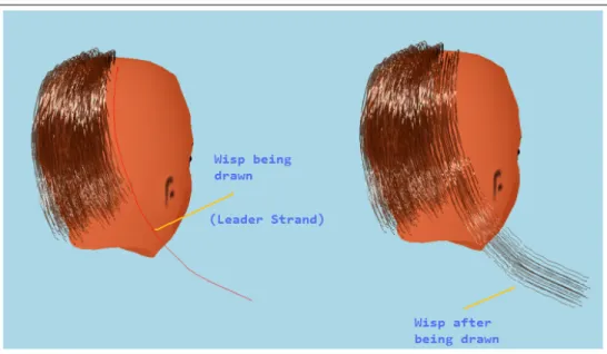
3.1 A wisp being drawn through the sketching interface. . . 19 ix
LIST OF FIGURES x
3.2 Two different self intersecting wisps. One forming a convex shape (circular) the other one a concave shape (will be discarded). . . . 22
3.3 The control points lying between the intersecting segments are rotated around the axis of rotation. . . 24
4.1 Two consecutive key frames. . . 26
4.2 Mapping of the wisps between two consecutive are done according to the locations of the roots on the patch structure. . . 28
4.3 Roots of the previous key frame are shown on the sketching screen. 29
4.4 The wisps are following the lead of the key strand. . . 29
4.5 The strand having less number of control points (6) is sampled to higher dimension to match the wisp with higher number of control points (12). 6 additional control points are added. . . 31
4.6 Path function created for a wisp. Below is an in-between frame following the path created by the function. . . 34
4.7 Hair strands reach their maximum speed during the in-between frame lying at the middle of two consecutive key frames. Speeds are always 0 at the beginning of key frames. . . 36
4.8 Two individual hair strands. One is under the influence of viscous air drag, the other one is not. . . 37
4.9 Sphere representing a hair wisp control point and a sphere repre-senting the head model, during collision. . . 38
5.1 A sequence of screenshots showing the in-between frames filling the gaps between 3 previously created key frames. . . 46
LIST OF FIGURES xi
5.2 Front view of a modern hair style created with the sketching inter-face. . . 47
5.3 Screenshot of an in-between frame during an animation. . . 48
5.4 A hair style created using the sketching interface. . . 49
5.5 A hair style created by a beginner user in approximately 4 minutes. 50
A.1 Sketching interface appears with a bald head model. . . 58
A.2 Parameters are passed via a Console Screen. . . 59
List of Tables
5.1 Characteristics of Usability Testers. . . 41
5.2 Test Tasks. . . 41
5.3 Task Completion Times. . . 42
5.4 Performance Results. . . 44
5.5 Performance Comparison with the dynamics hair simulation. . . 45
Chapter 1
Introduction
Hair has been one of the most striking aspects of any kind of computer gener-ated character animation. The vast amount of hair strands on a head, and the weakness of these strands against any kind of physical forces makes it a relatively complex phenomenon to animate. To target its difficulty, physically-based and key frame animation techniques have been proposed.
Physically-based techniques allow creation of realistic and high-quality ani-mations. Unfortunately this is not adequate for animators who aim to design the hair style from scratch, and also pre-define paths that the hair will travel through.
Under the influence of physical forces, the control over hair is none or too small. It is possible to exert pre-calculated forces to lead the hair strips into shapes and positions defined beforehand, but this is an inefficient and cumbersome task requiring lots of calculations. Furthermore, the results might be unsuccessful due to the nature of hair strands constrained by physical rules. However, with key frames and the free manipulation mechanisms this provides, the animator can decide the motion, the shape of the hair (as well as an individual hair strand) with total control in real time.
This total control gives the animator the chance to create physically-correct
CHAPTER 1. INTRODUCTION 2
(sufficiently realistic to trick our perception) animations, as well as animations without any constraints (not bound by any physical rules), such as totally chaotic, cartoon type animations, showing that there are no limits of the types of hair animations that can be produced, since the results are not bounded by physical constraints.
In this system, which is not bound by constraints, hair can be curled, elon-gated, twisted etc. without difficulty. These are animations that would stretch the limits of the powerful physically based animation systems, and translate the results to graphical animations.
Even when such systems do succeed in producing the intended animations, the results do not usually satisfy the requirements of the animator fully. The main aim of this thesis is to introduce a tool for creating hair styles with the use of a sketching interface; creating key frames using this interface (with or without the support of physical constraints); animating them and performing all the tasks in real time.
1.1
Previous Work
Different hair modeling techniques have been proposed to serve for different pur-poses. Individual particle-based methods [6][12][13], real-time animation solu-tions [2][15][16], representing detailed interacsolu-tions of the hair strands with each other [14] and interactive hairstyling systems [1][11] have all addressed different parts of the hair modeling and animation problem. Our proposed tool deals with three different aspects of the problem: Modeling the hair along with its stylistic properties through a sketching interface; creating the flow of the animation by defining key frames and controlling the animation of the hair model during and before the animation; and performing these tasks in real time with a direct ma-nipulation interface. Therefore, it would be appropriate to examine the previous work relevant to our method, classified with respect to these different aspects.
CHAPTER 1. INTRODUCTION 3
1.1.1
Hair Modeling and Animation
In spite of the easy definition and usage of individual hair strands, wisp based techniques are becoming widely used since they provide an efficient and collective way to represent hair. In their work Choe et al. [1] use a wisp based hair rep-resentation technique. They represent wisps with parameters like fuzziness that defines the wavy nature of the strands, deviation radius function which affects the distribution of the hair strands and length distribution which defines the lengths of the hair strands all together forming static hairstyles. This statistical model is supported by a styler used by employing constraints to the formed hairs. The styler is proposed to model artificial features that affect the natural flow of hair under gravitational forces, such as a hairpin. With the constraints and the statis-tical wisp model, realistic hair styles can be formed but due to excessive amount of calculations, results cannot be obtained in real time. In his paper Oshita [2] presents a method for real-time hair animation. He combines a dynamic hair generation technique and a conventional particle-based dynamic simulation. The movements of the coarse model (small amount of hair strands) are simulated us-ing a dynamic simulation at the beginnus-ing. Then a fine model is generated from the coarse model using a dynamic wisp model. The velocities of the particles in the coarse model define the shape of a wisp and the individual strands in the fine model during the simulation. The method is designed to work on GPU and works on real time simulating hair to hair interactions between hair strands in the same wisp.
1.1.2
Controlling Animations and Key Frames
From the animators point of view, animation creation has two important aspects: the quality of the animation, and the controllability of the animation. Sophisti-cated physical calculations and graphical calculations can be done in very short time intervals so that high quality animations can be created, fulfilling the first requirement of the animators, but controlling these animations is still a problem to solve. In Shi and Yu’s work [3], external force fields are applied to control the
CHAPTER 1. INTRODUCTION 4
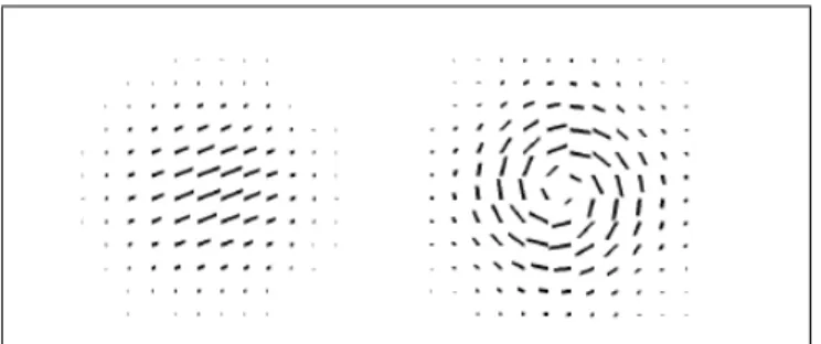
shapes of the liquids. Regular objects’ shapes are defined as target shapes, and the liquids are controlled by applying forces to match these changing target shapes. A gradient force field is defined by the shape of the target object combined with a feedback force field and both are applied to the liquid. In their work, Fattal and Lischinski [4] drive the smoke towards a given sequence of target smoke states. This control is achieved by two extra terms added to the standard flow equations that are (i) a driving force term used to carry smoke towards a target and (ii) a smoke gathering term that prevents the smoke from diffusing too much. Popovic et al. [5] use a continuous quasi-Newton optimization to solve for wind-forces to be applied to the underlying velocity field throughout the simulation to match the user-defined key frames. Their system is based on the algorithm presented in work of Stam [19]. In this framework, smoke simulation has states. A state consists of a grid r of densities and a grid v of velocity vectors. Animator controls the animation with smoke density and velocity key frames (Figure 1.1).
Figure 1.1: Smoke density and velocity key frames. (Smoke Simulation, Treuille et. al)
Simulation is computed from a start state q0. The latter states are then
calculated recursively via step function S for time t, qt= S(qt−1). The simulation
starts with an initial state and repeatedly the subsequent states are calculated. These calculated sequence of states form the simulation. An optimization process is used to produce the best matching states.
Physically-based hair animation has also been a subject of animation control. In Petrovics work [6], hair is represented as a volume of particles. To control hair, this method employs a simulation force based on volumetric hair density difference
CHAPTER 1. INTRODUCTION 5
between current and target hair shapes, which directs a group of connected hair particles towards a desired shape. Petrovic et al. use a mass-spring system in their hair structure and the forces are exerted to the strands through this structure. They create density grids for both the starting shape and the target shape (Figure 1.2).
Figure 1.2: Example drawing of density grids and force fields.
To match the density of the starting shape to the density of the target shape, they create a gradient force between the grids, pushing the hairs to their target shapes. Although the technique is successful to reach the target key frames when they are physically reachable key frames (under physical constraints, they can be reached via the use of forces), it cannot imitate the behavior of chaotic, non-physical hair styles.
1.1.3
Sketch Based Interaction
In a computer generated 2D environment, it is straight forward to map the inputs of the well-know input devices to the computer environment. The challenge is being able to map the 2D input data into a 3D computer generated space. In a previous work [20] a 3D input device for direct mapping to the 3D computer generated space is presented. The device consists of a stiff piece of paper which is tracked by a digital video camera. The piece of paper and its location represents a virtual plane in the 3D space. By drawing on the paper, the user can specify points in 3D space. But most of the time, the input devices are simple 2D devices. Being able to create 3D content via these input devices in an intuitive way is an
CHAPTER 1. INTRODUCTION 6
active research area.
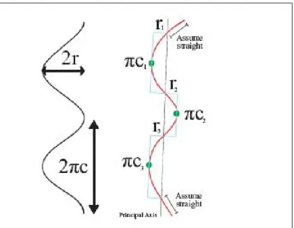
In their work Wither et al. [7] present a sketching interface for physically-based hair styling. The sketching interface does not involve 3D input, but a side view of the model is shown on the screen and the user inputs are reflected to this side image. The elastic parameters and the geometric parameters are extracted from the drawn hair strands. For inferring the strand parameters from a sketched 2D strand, the method detects the inflection points along the 2D stroke input by the user (to the side image), and uses them to cut the stroke into sections representing a half turn of a helix (Figure 1.3). Then the method fits these half helixes to segments. A volume stroke that is input by the user is used to set the hair volume. After this input, other strands are interpolated according to the volume stroke. Although, visually satisfying results are obtained by this technique, there exists a drawback. In this technique, the user input cannot be reflected correctly to the model. Bound by physical forces, the strokes of the users cannot always be transformed to the created hair strands as they imagined. Users eventually observe different hair strands than they input.
Figure 1.3: Half turn of a helix. (Super-Helices for Predicting the Dynamics of Natural Hair, Bertails et. al)
CHAPTER 1. INTRODUCTION 7
Another physically-based hair creation technique is proposed by Hernandez et al. [8]. They propose a paint tool to determine a set of gray scale images that allow them to establish hair length values and hair density values. For animations they use a simplified physically-based method that computes physics on basis hairs and distributes these calculations to other hair strands. Fu et al. [9] proposes a non-physically based hair design system equipped with a sketching interface and a fast vector solver. Users manipulate the global shape of the hair style via the sketching interface. Local control is not possible in this system in real time. Another non-physical hair design system was proposed by Malik [10]. He proposes a hair sketching interface manipulated via a tablet, to create hairstyles that are not bound by physical constraints. Hair is represented by wisp structures in his work. The wisp structure is defined by a number of parameters such as twist, density and frizziness. He also provides virtual tools such as combs or hair pins to change the hair style interactively via the help of gesture recognition algorithms.
Chapter 2
Hair and Head Structure
A persons head skin contains tens of thousands of individual hair strands, which, despite their large numbers, all share the same structure underneath. As a result, human head can be defined as a surface where there are very large numbers of hair strands that share exactly the same structural properties with each other; only located at different positions all around the head, with slight variations in shape. This allows us to create single hair strands and duplicate them.
2.1
Hair Strands
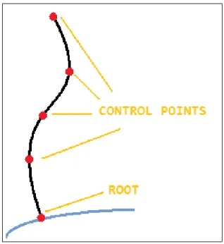
Hair strands consist of a number of control points (Figure 2.1). Each hair strand has a root control point that defines its location on the skull and does not change its location under any circumstance. Other control points define mainly the shape of the hair strand. These control points are input using the sketching interface. This process will be discussed in detail in the sketching section, further below.
After establishing a number of control points, according to their input se-quence, the first control point is defined as the root control point. The other control points are connected to each other with lines, to and from the structure of the strand (Figure 2.1). Directly connecting these control points results in lines
CHAPTER 2. HAIR AND HEAD STRUCTURE 9
Figure 2.1: Structure of a hair strand.
with many corners (looking zigzag-like line). To smooth out the corners in the lines we use a combination of Bezier and Catmull-Rom splines [21], as explained below.
The nature of Catmull-Rom splines requires us to provide four control points C1, C2, C3 and C4 to create a spline between C2 and C3. As the user gives n
inputs to our system, we need n + 2 control points to form a Catmull-Rom spline passing through these n control points. Therefore, at the beginning of spline formation, we extrapolate two control points, one to the beginning and one to the end.
To form a Catmull-Rom spline passing through many control points, we form groups of four control points iteratively. For a strand containing n control points, (n + 1) − 4 groups are formed. For example a strand containing 6 control points will have the following groups C1, C2, C3, C4; C2, C3, C4, C5; C3, C4, C5, C6
where Ci means the ith control point. From these control points, Bezier control
CHAPTER 2. HAIR AND HEAD STRUCTURE 10
BC0 = C0 (2.1)
BC1 = C1+ ((C2 − C0)/6)
BC2 = C2− ((C3− C1)/6)
BC3 = C2
These Bezier control points are calculated via GPU [22] saving important clock cycles of the CPU for other operations. Then these Bezier control points are fed into the Bezier Equation 2.2 to form the part of the Catmull-Rom spline, which will then be combined with the previously created splines to form the final Catmull-Rom spline.
For 0 ≤ t < 1,
B(t) = BC0(1 − t)3+ 3BC1t(1 − t)2+ 3BC2t2(1 − t) + BC3t3 (2.2)
2.2
Hair Wisps
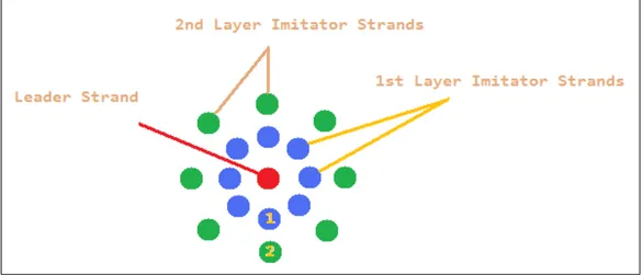
A hair wisp is a cluster of hair strands placed together, which has a leader hair strand in it. A number of hair strands are located around the leader hair strand, sharing the same properties such as length, number of control points (or mass nodes), curl, and color, with it. These are named imitator strands. They are evenly distributed around the leader strand, all having the same distance to it. During the style recording stage, the user creates the leader strand. Once the creation of the leader strand is completed, its identical copies are produced and wisp formation begins. With the formation of many wisps, the head is filled with hair. These wisps can have different styles than each other.
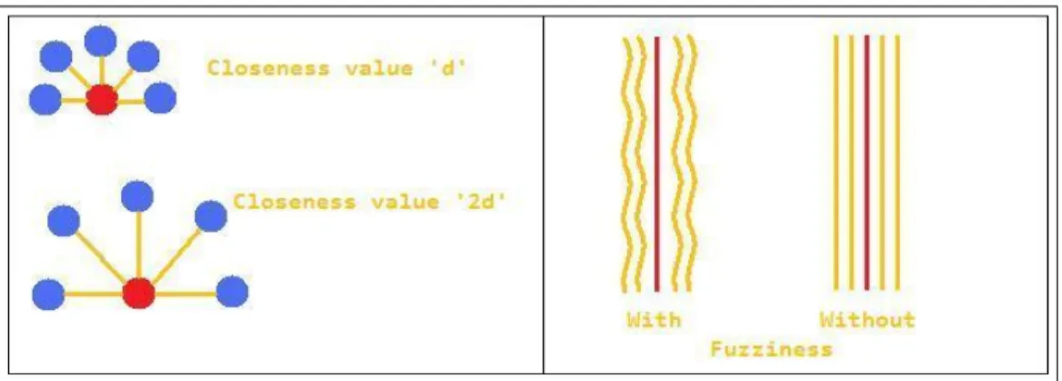
These different styles are represented by the following style parameters: close-ness ci,j, fuzziness fi,j and the number of strands in a wisp ni, where i is the id
CHAPTER 2. HAIR AND HEAD STRUCTURE 11
Closeness parameter is used for the purpose of defining how distant the im-itator strands are placed. According to the closeness values obtained from the wisp parameters, the root points of the imitator strands are determined in a two dimensional u,v coordinate system with a circularly layered arrangement (Figure 2.2). Each circular layer consists of eight imitator strands, closeness of these layers to each other are also the same with the closeness parameter. The value eight was chosen in order to be able to achieve an arrangement that is close to a circular shape. The imitator strands can be thought as placed in North, South, East, West, North-East, North-West, South-East and South-West directions.
Figure 2.2: Distribution of imitator strands.
The closeness value d fed to the system, is used to calculate the coordi-nates of each one of the eight imitator strands. The main four coordinates (North,South,East,West ) are calculated on the basis of the coordinates of the leader strands (Figure 2.3) on 2D u,v coordinate system as:
u + d, v; u − d, v; u, v + d; u, v − d; (2.3)
The root points of the imitator strands are distributed around the root point of the leader strands uniformly (with the same distance), using the employed patch structure defined in the following section.
CHAPTER 2. HAIR AND HEAD STRUCTURE 12
Figure 2.3: Closeness value effects how distant the imitator strands are placed. Fuzziness value gives a wavy look to the hair wisp.
The closeness values are used along the imitator strands. In other words, when root points are placed at a distance from the root point of the leader strand using the closeness value, the upper level control points are placed in the same manner. Similar to the root points, they are placed around their corresponding control point of the leader strand. This creates duplicate imitator strands, spaced from the leader strand by a distance determined by the closeness value. In order to create more realistic, uneven looking wisps, a fuzziness parameter is used. This is a random value between 0 and 1 and is used to change the location of the control points in small increments, so that the imitator strands, instead of being an exact copy of the leader strand, would have their own characteristics and wavy appearances, but still obey the movements of the leader strand (Figure 2.3).
2.3
Head Structure
The head model appearing on the animations is created using AutoDesk 3ds Max [18] software. The model is defined by a triangular dataset. Instead of using the triangular head dataset as the base for the hair strands, we define and fit an invisible patch structure under the scalp and use it as the base for the hair strands.
CHAPTER 2. HAIR AND HEAD STRUCTURE 13
Using the mesh representation of the 3ds Max model for root point positioning might seem reasonable, as it would provide us with an easy way of placing the root points on the mesh points, since all the coordinates of these points are already calculated and available. However, there are some drawbacks of using this approach, such as:
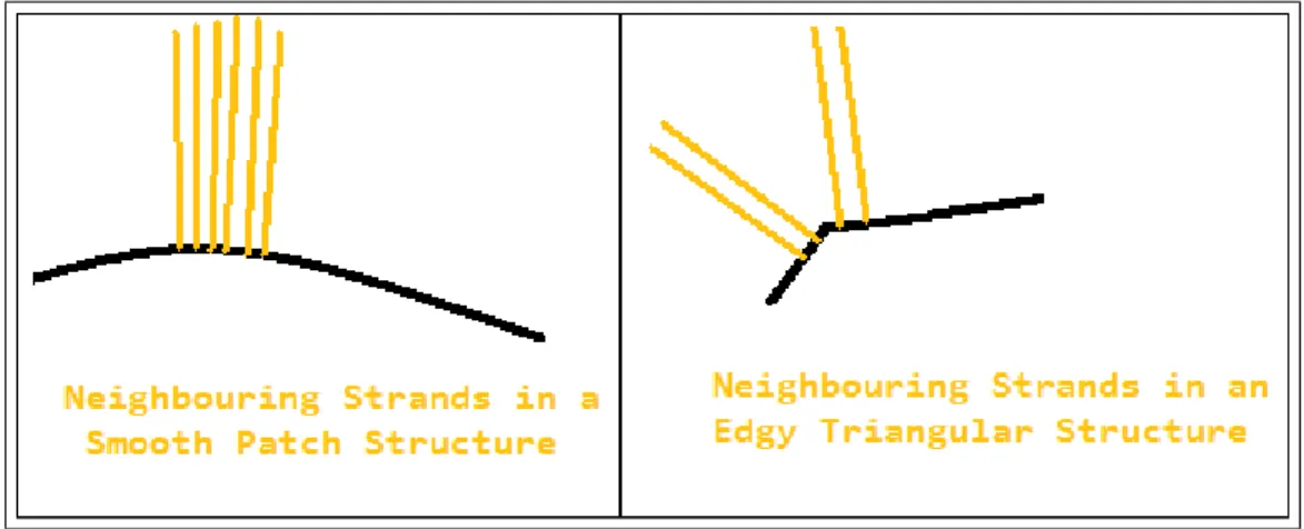
• The first drawback is related to obtaining neighborhood information. As we have discussed before, we are using a wisp structure that contains a leader strand and neighborhood strands. In order to find the root point positions of the neighboring imitator strands, unlike in patch structures, additional computations would be required since the calculations are done in 3D space. • The second and most important drawback is the problem of triangle edges. A root located near an edge of a triangle might require one of its neighbors to reside on another triangle (which might happen to have a different normal than the current one). Thus imitator strands will exist that cannot actually imitate the direction of their leader strands (Figure 2.4).
Figure 2.4: An example of a possible drawback of using triangular dataset rather than a patch.
Because of these drawbacks we use a patch structure under the scalp (Figure 2.5). Reducing the three dimensional head structure into a two dimensional space, finding neighboring information becomes a relatively easy and efficient task. Also,
CHAPTER 2. HAIR AND HEAD STRUCTURE 14
the problem of having dramatically different slopes between an imitator strand and leader strand is prevented.
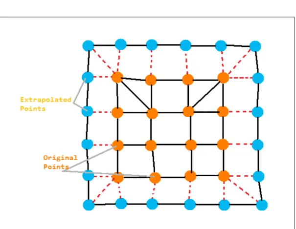
The patch structure under the scalp is formed by using a combination of Catmull-Rom splines, forming a grid-like structure. The reason for using a Catmull-Rom patch is to be able to create a patch that is very similar to the head shape. Since Catmull-Rom patch has a property that the patch structure always passes from the control points; by selecting a set of control points on the head structure, we guarantee that the patch will fit to the head. We used a 6 by 6 (total 36 control points) Catmull-Rom patch underneath the head structure. These control points are distributed evenly on parts of the head structure that normally contain hair.
However employing a Bezier patch would be an easier decision from an imple-mentation point of view. The reason that makes Catmull-Rom patches a more difficult option is the nature of Catmull-Rom patches that require us to extrap-olate the control points we provide (Figure 2.6). While creating a Catmull-Rom spline, it is obligatory to provide 4 control points. If not possible, extrapolation shall be done. Same requirements also exist for closed shapes.
The extrapolated coordinate values Ci,j (Figure 2.6) of the extra control points
are calculated according to their locations around the grid. In a grid with n + 1 rows and n + 1 columns, if the extrapolated control point is along the first row (C0,j) or the last row (Cn,j), extrapolated coordinates are calculated via Equation
2.4.
Ci,j = Ci+1,j ∗ 2 − Ci+2,j; (2.4)
Ci,j = Ci−1,j ∗ 2 − Ci−2,j;
i 6= j;
If the extrapolated control point is along the first column (Ci,0) or the last
CHAPTER 2. HAIR AND HEAD STRUCTURE 15
Ci,j = Ci,j+1∗ 2 − Ci,j+2; (2.5)
Ci,j = Ci,j−1∗ 2 − Ci,j−2;
i 6= j;
The final extrapolation calculations are performed to form the control points at the corners of the grid. To calculate extrapolated control points located at the four corners C0,0, C0,n, Cn,0 and Cn,n, Equation 2.6 is used.
C0,0 = C1,1∗ 2 − C2,2; (2.6)
C0,n= C1,n−1∗ 2 − C2,n−2;
Cn,0= Cn−1,1∗ 2 − Cn−2,2;
CHAPTER 2. HAIR AND HEAD STRUCTURE 16
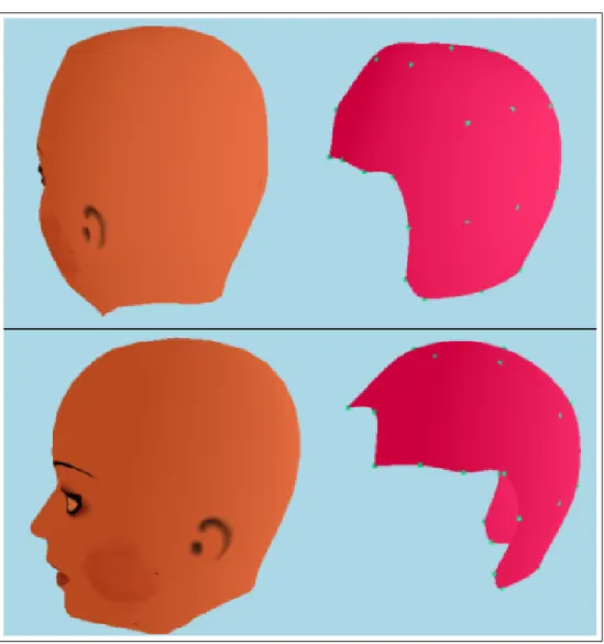
Figure 2.5: The head model and the Catmull-Rom patch structure representing it.
CHAPTER 2. HAIR AND HEAD STRUCTURE 17
Figure 2.6: Extrapolation of control points is needed since we are using a Catmull-Rom patch structure. Grid in the figure contains 6 rows and 6 columns.
Chapter 3
Sketching
We propose a sketching interface for direct manipulation of hair strands. The head model lies inside a 3D space. The user, by using an input device (a mouse, a stylus pen etc.) directly draws the hair strands on the 3D head (Figure 3.1). Each movement of the input device is recorded and reflected to the head model and hair is created. The movements are mapped into 3D space and the control points are recorded in uniform time steps. The details are explained in the following subsections.
3.1
Input Mapping
The input devices used to interact with the computer are usually two dimensional devices. In order to be able to draw hair strands on a head that is located in a 3D space, these two dimensional input coordinates should be correctly mapped to the world coordinates of the 3D space. To correctly reflect what is inputted through our devices and draw the hair strands into a 3D world, two important steps should be achieved. These are: (i) create a 2D plane on which these inputted values will be drawn parallel to the computer screen, and (ii) find the depth of this plane. This plane is called the drawing plane.
CHAPTER 3. SKETCHING 19
Figure 3.1: A wisp being drawn through the sketching interface.
3.1.1
Drawing Plane
The hair strands are created on a two dimensional plane (since inputs are 2D). To be able to correctly define the location and slopes of the drawing plane, we have to find the depth of the plane and its slope.
The slope of the drawing plane is calculated by the angle of the viewing vector of the camera. Thus the screen of the computer is actually the drawing plane of the user. Drawing experience of the user is aimed to be similar to drawing to a regular painting program.
If the system was working on a 2D space, the drawing task could have been easily accomplished. The drawing plane would be located right behind the screen, parallel to it without any depth. But, in a 3D space, we also have to calculate the depth of this plane. We should decide whether the user is drawing the strand on the top of the head, or to the forehead etc. To calculate the exact point where the user is drawing, we use the depth buffer. The task is accomplished as follows:
CHAPTER 3. SKETCHING 20
2. After the depth buffer is cleared, the patch is rendered filling the depth buffer by its coordinates.
3. When the user clicks on the screen, we use OpenGL’s [23] glReadPixels function in order to get the clicked pixel and search the depth buffer for that pixel to find out if it is containing an object.
4. If the result is a hit (it hits a rendered location in the depth buffer) the coordinates are projected to world coordinates by OpenGL’s gluUnProject function. Then, a drawing plane which is parallel to the screen and passing through that point is created. As the drawing continues, the control points are drawn on this plane with the same methodology, after the patch is rendered, the invisible plane is rendered and its position is read from the depth buffer so that the drawn control points are located on this plane.
3.1.2
Root Positioning and Wisp Formation
The first input on the screen after an idle state is always assumed to be a candidate root point of a hair strand. The point is checked whether it belongs to the patch structure or not. If it is on the patch, the control point is created there and as the drawing continues the inputs are converted to the drawing plane and visualized there. Once the user stops input, all the collected control points are fed into the GPU and a Catmull-Rom spline is created, forming the structure of the hair as we defined on Chapter 2. Lastly the rendering effects are applied such as spline creation for smooth appearances, supported by Kajiya and Keys illumination model which is defined further below, to complete the final touch [24].
3.1.3
Gesture Recognition
As we have mentioned before, the drawing interface provides a 2D invisible draw-ing plane which is parallel to the screen. The movements of the mouse or digital pen are reflected directly onto this plane. Since it is 2D, occasionally some inter-sections will occur (on the drawings), especially if the user is drawing a long hair
CHAPTER 3. SKETCHING 21
strand with lots of curves. These intersections, or loops, should be detected and taken care of. Instead of just avoiding these intersections, or preventing the users from being able to create such conditions, we take a different approach and pro-vide the intersection situations as a means of interface; an interface for creating curly 3D hair drawn on the 2D plane.
In order to avoid self intersecting hair strand creation during the hair drawing process, and also provide a chance for creating 3D curling hair, we detect the in-tersections occurring in the strand. To detect if the hair is intersecting with itself, we divide it into imaginary hair segments. We assume that each two consecutive mass points are connected with a linear segment and all intersection calculations are done on these. We use formulas (3.1) and (3.2) to detect intersections be-tween two segments n and m where xn1, xn2, yn1, yn2 are x and y coordinates of
the beginning point and ending point of segment n, and xm1, xm2, ym1, ym2 are
x and y coordinates of the beginning and ending points of the segment located after segment n (segment m).
u1N = ((xm2− xm1) ∗ (yn1− ym1)) − ((ym2− ym1) ∗ (xn1− xm1)); (3.1)
u1D = ((ym2− ym1) ∗ (xn2− xn1)) − ((xm2− xm1) ∗ (yn2− yn1));
u2N = ((xn2− xn1) ∗ (yn1− ym1)) − ((yn2− yn1) ∗ (xn1− xm1));
u2D = ((ym2− ym1) ∗ (xn2− xn1)) − ((xm2− xm1) ∗ (yn2− yn1));
u1 = u1N/u1D; u2 = u2N/u2D;
According to these calculations, if both u1 and u2 lye within the range 0-1;
these two segments are intersecting with each other. Intersection detection is performed between all segments satisfying the condition m > n. Each segment is tested for intersection for the segments after them. This is a precaution prevent-ing double calculations. After detectprevent-ing the intersections we take the followprevent-ing approach to create a 3D curling hair model. The intersections that have a poten-tial to form curly hair are selected if they satisfy the following two constraints:
CHAPTER 3. SKETCHING 22
condition occurs, the segment that is nearest is (m − n value is the smallest) chosen and the others are discarded. The curly hair partition is formed via only one intersection point.
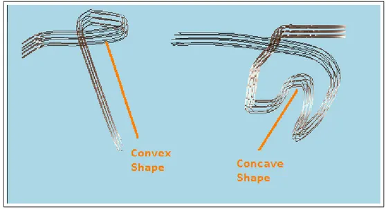
2. After the intersecting segment is chosen, if the segments between the chosen pair do not produce a convex polygon, this means that the loop does not represent a curling hair and shall be discarded (Figure 3.2).
Figure 3.2: Two different self intersecting wisps. One forming a convex shape (circular) the other one a concave shape (will be discarded).
If all these constraints are satisfied, the drawing is detected as a loop. The two dimensional loop should be converted into a 3D helix-like shape in order to achieve a curly hair look. Three steps for forming the helix structure are as follows:
1. The focal point of the loop has to be found. Each of the segments lying between the intersecting segments (between n and m) are examined one by one and their center of gravity coordinates are calculated. The mean value of these segments is defined as the focal point of our loop.
CHAPTER 3. SKETCHING 23
Fx= sumCxn/totalsegments;
Fy = sumCyn/totalsegments;
Fz = sumCzn/totalsegments;
Where Cxn, Cyn and Czn are the coordinates of the center point of segment
n. Average of all the center points are calculated and one focal point F is found. A rotation axis defined by the beginning of segment, intersected segment, and the end of intersecting segment is formed.
2. The axis is then translated to the focal point of the loop, which will be the rotation axis that turns the two dimensional loop into a helix. The rotation amount must be 360 degrees along the loop. The last control point has to connect to the other segment naturally. According to the number of segments on the loop, the rotation amount is calculated. A loop containing n segments will have 2n − 1 points to be rotated (every segment has two control points). Each of these points will be rotated according to their index i on the loop (Figure 3.3) according to formula:
Rot = (360/(n ∗ 2 − 1)) ∗ i; (3.3)
3. After the rotation finishes, the mass nodes in this loop are mapped to a helical structure, thus producing a 3D curly hair.
CHAPTER 3. SKETCHING 24
Figure 3.3: The control points lying between the intersecting segments are rotated around the axis of rotation.
Chapter 4
Key Frame Animation and
Rendering
Being able to provide an intuitive interface both for styling and creating hair led the way for key frames. With the sketching interface, it is possible to define key fames, edit and combine them, to form a real time hair animation.
Hair wisps are drawn on the 3D head model and their positions are recorded as key frames. After key frame creation is finished, in-betweening stage starts. The in-betweening stage is responsible for calculating the transition functions and mapping of wisps between the key frames. The whole key framing stage consists of the following steps.
1. 3D Key frame recording via the sketching interface,
2. Switch to in-betweening stage with wisp matching, wisp mass sampling, path function creation stages,
3. Animation stage consisting of running the correctly formed in between frames with the ability to provide a touch of randomness with viscous air noise force,
4. For efficient transitions slow in, slow out methods. 25
CHAPTER 4. KEY FRAME ANIMATION AND RENDERING 26
5. Collision detection.
4.1
Key Frame Recording
The drawing interface is used as the key frame recording tool. User can draw any type of hair through this interface. Once the drawing of a key frame is finished and it is recorded; the skull is cleared for the next key frame and user starts drawing the next frame. This way, sequentially the key frames are defined. For each key frame, once hair drawing is finished, the coordinates of the hair strands are recorded for later usage. So for each key frame, the previous frame’s root locations, and complete 3D view are still available, giving a better key frame definition process. After drawing again the key frame is recorded and the skull is cleared for further key frame drawing. Any number of key frames can be created with any number of hair strands on them this way.
Once the key frame definition process is finished (after the last key frame is recorded); the in-betweening stage starts operating. Having the key frames in hand, we need to create in between frames (Figure 4.1).
CHAPTER 4. KEY FRAME ANIMATION AND RENDERING 27
4.2
In-Betweening Stage
The key frames are snapshots of the animations most dramatic moments. The frames lying between them are usually regular frames (changing regularly). These regular frames should be created successfully. The in-betweening stage is the most crucial stage of key frame based hair animation, since it fills the gaps between the key frames provided to the interface, with correctly calculated in-between frames (The number of in-between frames, for each two consecutive key frame, is defined by the user before key frame creation). The stage consists of the following main steps, Wisp Matching, Wisp Mass Sampling, Path Function.
4.2.1
Wisp Matching Between Key Frames
Since there are no limitations on the animation length, there can be any number of key frames provided to the tool. Each of these key frames might potentially contain hundreds of hair wisps. A mapping between two consecutive key frames has to be done in order to decide which wisp in the current key frame should aim which wisp in the latter one (Figure 4.2). One solution might be forcing the user to draw each wisp on the exact same location on the skull for each frame. Accomplishing this purely by the user is very difficult; also forcing the user through the system to do this takes the freedom away. So the wisps can be drawn to any location on the skull and these hair wisps of each key frame should be correctly mapped to the hair wisps on the next key frame to achieve a realistic simulation. For instance, a hair wisp located above the right ear in a key frame should be mapped to a hair wisp again located above the right ear on the next key frame. Without this constraint, the effect would be similar to mapping the right leg to left leg in a walking animation. This might not cause very dramatic effects if the animator chooses to create regular animations, i.e. animations in which all the strips are uniformly swing to one place (doing same kind of movements). But once some irregularity is introduced via key frames (for example a twisting hair, or separately swinging hair wisps), irrelevant movements might occur.
CHAPTER 4. KEY FRAME ANIMATION AND RENDERING 28
Figure 4.2: Mapping of the wisps between two consecutive are done according to the locations of the roots on the patch structure.
To prevent this unwanted effect to occur, we carefully map each wisp to one in the next key frame. The in-betweening stage controls each two consecutive key frames and all of the wisps created during these key frames. As we have defined before, the skull is parameterized as a 6x6 3D Catmull-Rom patch. All hair wisps have their roots on this patch, and their root coordinates are located as a 2D point in u, v coordinates on this patch. To find the most suitable wisps (the ones that have the closest root locations) in consecutive key frames, we calculate the distances of the root locations of each wisp with others. Since they all have their roots on the same patch, and the patch is in 2D space; it is easy and fast to calculate these values. The wisps having the closest 2D Euclidian distance in parametric space are mapped to each other. As a summary; root position of the current wisp is taken and it is compared to the wisp root locations on the next key frame. The closest one is found and selected as the target wisp.
Through the interface on the surface of the skull, the locations of the pre-vious key frames root locations are shown on demand, reminding the user how the previous key frame was drawn (Figure 4.3). Even if the roots are drawn to completely unrelated places, good animations can still be produced, but the
CHAPTER 4. KEY FRAME ANIMATION AND RENDERING 29
achieved animation might have some differences with the key frames provided to the system (since the roots of the wisps are different while drawing). Thus the usage of previous frames snapshots gives a chance to further enhance user input.
Figure 4.3: Roots of the previous key frame are shown on the sketching screen.
Key Leader Strand. Hair animations that involve similar movements of hair strands is a usual situation. Swinging hair, become electrified, grow from short hair to long hair are all animations that involve hair strands that share similar motion characteristics. For these kinds of animations, to ease the usage of sketch-ing tool, the user can take the advantage of ussketch-ing key hair strands. Instead of drawing each hair wisp through the interface, it is possible to define a key leader strand, and map the actions of all hair wisps to it so that all hair wisps will follow the guide of the leader strand(Figure 4.4).
CHAPTER 4. KEY FRAME ANIMATION AND RENDERING 30
4.2.2
Wisp Mass Sampling
After the wisp mapping stage is completed, each wisp on each key frame has a specific target wisp on the next key frame but their structures might have differences. Hair wisp lengths can be different than the mapped hair wisp and they most certainly will be since they are created by user inputs. Irregularities of this should be supported since any kind of hair animation can be created by the system such as growing hair, or hair that is shortening. Having different number of mass nodes between two mapped hair wisps causes the problem of extra mass nodes having no target location. To be able to overcome this problem, wisp mass sampling methodology is used. The number of mass nodes of the mapped wisps that are different should be made equal to each other. A wisp consisting of n mass nodes mapped to a wisp on the latter key frame having n + m nodes will require the wisp sampling stage to introduce it m new mass nodes and distribute these evenly throughout its structure (Figure 4.5).
The mass sampling stage operates through the following three steps:
1. Numbers of mass nodes m1, m2of the two mapped hair wisps are compared.
If they have the same value, no sampling is required. If they have different values, the difference d is calculated (d = m2 − m1 if m2 > m1 AND
d = m1− m2 if m1 > m2). This value will be used in stage 2 as the number
of extra mass nodes.
2. After calculating the number of the needed number of extra mass nodes d, the issue about distributing these evenly between the existing mass nodes (i.e. on segments connecting the control points) should be solved. Dis-tribution task is operated iteratively. For each segment we have a value n indicating the number of extra control points that were added to that segment, which is zero at the beginning. On each iteration we add 1 extra control point to each segment and decrement the value d by 1. Once we reach the last segment, we begin a new iteration from the beginning. When value of d reaches 0, i.e. the number of control points of the two mapped wisps match with each other, step 3 begins.
CHAPTER 4. KEY FRAME ANIMATION AND RENDERING 31
Figure 4.5: The strand having less number of control points (6) is sampled to higher dimension to match the wisp with higher number of control points (12). 6 additional control points are added.
3. To adapt the new control points into the structure, the extra control points should be distributed evenly on each segment in 3D space. This is required to preserve the structure of the hair wisp (it shall not change after the sampling stage). To achieve this aim, the extra control point numbers (n) of the segments are used. A segment having n extra control point is divided into n + 1 equal sub-segments, and the control points are placed on the end points of these segments. Since the newly added points lye on the same segment, and they are distributed evenly on it, hair wisp preserves its structure and shape.
Now the animation between these two hair wisps can be processed. Extra mass nodes are added to the line connecting the older mass nodes uniformly so
CHAPTER 4. KEY FRAME ANIMATION AND RENDERING 32
that their addition does not cause any change in hair wisps shape.
4.2.3
Path Function Creation
After matching the wisps between key frames and sampling their control points to fit each other, definition of the path they will take between two key frames should be defined. During animation, each hair wisp will follow the path created in this stage to reach its target shape and location. Since each hair wisp consists of control points, the paths are actually defined for each of these control points. During the in-between frames, these control points traverse the linear path as-signed to them, and once the next key frame is reached, they have to be in the correct position.
Path function creation requires two inputs; the current wisp, the target wisp and the number of in-between frames between key frames. Then the following calculations take place separately for all wisps:
1. The coordinate values of each control point belonging to the current wisp and the target wisp are gathered. For each control point on the current wisp, in order to find out how much distance should they travel, the dis-tance to the target wisps corresponding control point is found (control point having the same index on the wisp). Distances for each coordinate axis are calculated separately where dx = xt− xc, dy = yt− ycand dz = zt− zcwhere
d stands for distance and x, y, z values represent coordinates. Subscripts t and c stand for target wisp and current wisp respectively.
2. According to the calculated distance values, how much distance should each control point travel is known. Dividing these values by the number of in-between frames input by the user, the distance that should be traversed by each control point in each in-between frame is calculated. dx = dx/n,
dy = dy/n and dz = dz/n
CHAPTER 4. KEY FRAME ANIMATION AND RENDERING 33
their locations gradually according to the calculated path function. On each in-between frame, the nthcontrol point of wisp m moves, d
xn−m on x axis, dyn−m on
y axis and dzn− m on z axis. These 3 values are actually the speeds of the control
points along the coordinate axes. In each time frame (in-between), they traverse the distance according to their speeds (Figure 4.6). This is a linear interpolation methodology where the time to translate from one frame to the other is defined by the number of in-between frames. The path functions are created during drawing phase, so once the animation starts, no calculations regarding the positions of the wisps and their control points are made. This aspect helps us achieving the real time animation goal.
The path function data are kept in memory. The number of path functions that will be created throughout the recording stage is directly proportional to the number of wisps, number of control points of each of these wisps and the number of key frames. Total amount can be calculated by the formula:
T otalpath = kn∗ wn∗ cn (4.1)
where kn, wn and cn stands for number of key frames, number of wisps and
average number of control points for each wisp, respectively. For an animation consisting of 5 key frames, 50 wisps and an average of 10 control points of each wisp, there should be 5 * 50 * 10 = 2500 path functions.
Being able to access this large amount of data needs an indexing scheme. We record each wisp into the memory in an array using the drawing order of them. The order they are drawn is assigned to them as their index. For each key frame, a separate array of wisps are recorded with the same indexing methodology. After the wisp mapping stage concludes, each wisp has a pointer to the target wisp. The same recording strategy is used for path functions, so that these two arrays are mapped to each other. Later on during animation, by the use of indexes, path functions are reached.
During animation stage, a real-time viscous air drag noise is reflected to the animating hair strip. Its aim is to give the hair a wavy look while it is being
CHAPTER 4. KEY FRAME ANIMATION AND RENDERING 34
Figure 4.6: Path function created for a wisp. Below is an in-between frame following the path created by the function.
animated. To further enhance the quality of animation and provide smooth and realistic transitions, slow-in and slow-out systems are introduced, defined below.
4.2.4
Slow-in Slow-out and Viscous Air Drag Noise
The number of in-between frames input by the user defines how sensitive the animation will look. Having a large number of in-between frames means the control points will translate by little amounts (high sensitivity). This also de-fines the speed of the animation. The number of in-between frames is inversely proportional with the speed of the animation.
CHAPTER 4. KEY FRAME ANIMATION AND RENDERING 35
The speed of key frame animation can be defined by changing the number of in-between frames, but since the speeds of hair wisps are constant between each key frame, non-natural movements of the hair wisps can be encountered.
We introduce a slow-in / slow-out scheme for individual control points for more natural interpolation. Slow-in / slow-out alters the speeds of the control points according to the index of the in-between frame (the in-between frame they currently are shown on). The method aims to achieve the following task:
• As the new frame begins, the hair wisps are motionless
• Gradually they start accelerating until the half way of the control points path is traversed
• Then gradually decelerate until reaching the next key frame and stop there
Speeds are calculated according to Equation 4.2. The in-between frame at the middle (i.e. on an animation defined with n in-between frames; the frame number n/2) frame has the highest speed (normalspeedx2), while the beginning and end in-between frames have the lowest (Figure 4.7).
si = (nf/(nib+ 1)) − nf/(nib+ 1); (4.2)
speednew = speedold∗ (2 − abs(si));
Where si is the index of the current in-between frame, nf is the number of
frames so far, and nib is the number of in-between frames chosen between two
key-frames.
Slow-in / slow-out system might have a possible drawback. While it is increas-ing the quality of animations involvincreas-ing hair wisps that change their directions frequently (for example swinging), they can lead to unrealistic results in regular animations. A hair wisp falling down from the top of the head, or continuing
CHAPTER 4. KEY FRAME ANIMATION AND RENDERING 36
Figure 4.7: Hair strands reach their maximum speed during the in-between frame lying at the middle of two consecutive key frames. Speeds are always 0 at the beginning of key frames.
its movement along the same direction on two consecutive key frames should not slow down and stop during the movement. These kinds of movements should be continuous. We introduced a direction check constraint in our tool. The slow-in / slow-out method checks the general direction of the hair strands mass nodes in 3D space. The directions of each control point are their velocities on x, y and z axes. General direction of the hair wisp is the average value of these velocities again on x, y and z axes. After finding the general direction of each wisp, the same calculations are done for the corresponding hair wisps on the next frame. Then these general direction values are compared by examining their signs (neg-ative or positive). A sign change means a directional change on that axis. If a direction change is detected on x, y or z component slow-in/slow-out operates on the axes that have direction change. Thus, if a hair is swinging to the left and then to the right, its x direction component is changing its direction leading to a slow-in / slow-out effect performed on its x direction speed whereas if the hair is swinging to right and is continuing this motion on the next frame, no slow-in / slow-out effect is produced for the x axis.
Besides slow-in slow out, to improve the quality of the animation; a touch of randomness should be introduced into the system as well. In real life situations, since all of the elements around encounter a resistive force (friction), we should
CHAPTER 4. KEY FRAME ANIMATION AND RENDERING 37
Figure 4.8: Two individual hair strands. One is under the influence of viscous air drag, the other one is not.
also include this into our animation system. The force is viscous air resistance force, which in our application is the force that gives our hair a wavy randomly moving simulation look. To be able to reflect this into our key frame interface, we add an extra randomized noise value to our path function that edits the positions of each mass node during run time. From root to top, this noise is introduced to the control points of the hair wisp but the values are different for different mass nodes. If the node is near to the surface, the viscous air drag force is not too effective, but once we reach to the top parts of the hair, it becomes more apparent, preventing the stick like effects during hairs motion (Figure 4.8).
To provide a wavy look, for each coordinate axis, the direction to apply the noise is again randomly calculated. This random value decides whether to apply the noise in the negative or the positive direction. As control points continue moving on each in-between frame, the noise values are applied to their coordinates to deviate their locations on a small scale. The magnitude of the random values can be scaled during run-time by the user through the keyboard.
CHAPTER 4. KEY FRAME ANIMATION AND RENDERING 38
4.2.5
Collision Detection
The excessive amount of hair strands that are being animated have a high poten-tial of penetrating inside the head model during animation. Even though the key frames are collision free, during the in-between frames, hair wisps might intersect with the head model, leading to unrealistic animations. We are representing the head model and the hair wisps with spherical volumes to detect hair to head col-lisions which is an efficient method requiring low amounts of calculations. Hair to hair collisions are not taken into consideration to fulfill the real time requirements of the animations.
The head model is represented by three spheres; located and sized manually. Hair wisps are represented by n − 1 spheres having radii ri where n is the total
number of control points (centers) and i is the index of the control point. Radii of these spheres are calculated according to the closeness value and the number of layers of imitator strands. A control point having a closeness value x, with m layers of imitator strands will be represented by a collision sphere having a radius x∗m. At each in-between frame, collision check is performed between each sphere (representing the hair wisp) against head model spheres. If the distance between the center points of the two spheres d, is less than the sum of their radii r1+r2,
then a collision is detected. Penetration amount is calculated as r1+r2-dand the
control point is translated to the outside of the head sphere according to this value along the vector c1-c2 (Figure 4.9).
Figure 4.9: Sphere representing a hair wisp control point and a sphere represent-ing the head model, durrepresent-ing collision.
CHAPTER 4. KEY FRAME ANIMATION AND RENDERING 39
4.2.6
Rendering and Lighting
In most of the hair animation systems, the lighting of the hair is done using Kajiya and Kay illumination model [24] The reason for its common usage is that it supports anisotropic light effects. This illumination model enabled us to form stripes of lights over the hair groups. The most important aspect of Kajiya and Key that differs from other illumination models is the usage of the tangents of the hair strands in the lighting equations instead of the normals. In the graphics rendering pipeline, after the vertex shader program manipulates the input vertices, then these vertices and their tangent values are fed into a fragment shader program, where the calculations Kajiya and Kay lighting takes place according to Equation 4.3.
lp = kdsin(T, L) + ks∗ ((T.L)(T.V ) + sin(T, L)sin(T, V )) (4.3)
Where T is the tangent value of the hair segment, L is the light vector and V is the viewing vector and sin(T, L) is the angle between T and L vectors. Along with the Catmull-Rom spline and patch creation calculations, Kajiya and Kay rendering and lighting calculations are also done in GPU for each frame saving important clock cycles of CPU for other operations. For each frame, each hair strand should be illuminated and rendered. Position calculations, collision detection, slow-in and slow-out calculations etc. are all done in CPU which is already under heavy calculations. Performing the rendering related calculations such as illumination and spline creation on GPU leads to a more efficient workload both on CPU and GPU.
Chapter 5
Results
5.1
Usability Tests
The Usability tests are applied to sixteen people (Usability Testers) from various educational backgrounds. They were assigned two different tasks. One of the tasks was hair design and the other one was a key frame design. The character-istics of the persons taking the tests are shown in Table 5.1.
In the hair design task the usability tester was asked to create a hair style similar to his own, using a mirror and the sketching interface of the software. In the Key frame design, on the other hand, the Usability Tester was first required to create a hair style with long wisps and then swinging them to the right using three key frames (Table 5.2). The main aim of these usability tests are understanding how new users react to this completely new design environment and how much time does it take for them to adapt to it. By measuring the time it takes for them to create their own hair styles, we are investigating how they reflect their drawing abilities through the sketching interface and how long it takes. By measuring the time it takes for them to create an animation consisting of a swinging hair, we aim to investigate how the new users make use of the key frame animation system and how fast they are able to use it.
CHAPTER 5. RESULTS 41
Table 5.1: Characteristics of Usability Testers.
Testers Occupation Age Drawing Exp.? Computer Graphics Exp.? T1 Computer Engineer 24 YES NO
T2 Computer Engineer 25 YES NO T3 Manager 31 YES NO T4 Industrial Engineer 25 YES NO T5 Mine Engineer 23 YES YES T6 Computer Engineer 24 YES YES T7 Civil Engineer 24 YES NO T8 Manager 35 YES NO T9 International Relations 24 YES NO T10 Lawyer 25 YES NO T11 Electric-Electronic Engineer 25 YES NO T12 Industrial Engineer 23 YES NO T13 City Planner 29 YES NO T14 Industrial Engineer 24 YES NO T15 Computer Engineer 25 YES YES T16 Computer Engineer 23 YES NO
Table 5.2: Test Tasks.
Tasks Details
Task1 Develop own hair using sketching interface Task2 Develop long hair, swing to right with 3 key frames
Table 5.3 gives the completion times of this test.
It took an average of 2 minute 05 seconds for a first time user to sketch his hair style on the computer, while creation of animation with key frames took an average of 5 minutes 05 seconds. The completion times do not include the time spent in explaining the test procedure. During the performance of the Usability tests the following observations were made.
Hair Styling Design. The Usability Testers were all capable of creating the desired hair styles following a brief explanation of what they should be doing. After creating a few wisps, they all started creating their own hair styles. This
CHAPTER 5. RESULTS 42
Table 5.3: Task Completion Times.
Usability Tester Task 1 Completion Time Task 2 Completion Time T1 1 minute 45 seconds 4 minutes
T2 1 minute 45 seconds 3 minutes 50 seconds T3 2 minutes 5 seconds 5 minutes 15 seconds T4 2 minutes 15 seconds 4 minutes 35 seconds T5 1 minute 25 seconds 3 minutes T6 2 minutes 30 seconds 4 minutes 20 seconds T7 1 minute 40 seconds 4 minutes 45 seconds T8 3 minutes 7 minutes 5 seconds T9 2 minutes 5 seconds 4 minutes 35 seconds T10 1 minute 55 seconds 4 minutes 55 seconds T11 1 minute 30 seconds 4 minutes 10 seconds T12 2 minutes 55 seconds 5 minutes 35 seconds T13 2 minute 05 seconds 5 minutes T14 2 minutes 3 minutes 55 seconds T15 1 minutes 50 seconds 4 minutes 10 seconds T16 1 minute 40 seconds 4 minutes 10 seconds
indicated the simplicity of the interface used. Especially the testers that had prior experience on drawing applications adopted easier. The created hair styles were usually more successful when the tester had long and straight hair, whereas testers with short hairs had a bit more difficulty compared to the others. The main reason for this can be; since the long haired users usually start with a long hair wisp, that wisp helps the user to visualize the general hair shape that will be achieved. Thus, for the following strokes the user has an idea about how to continue. This is a bit more difficult for a tester with short hair, having more minor details to take care of.
Key Frame Design. In this test, the learning process took slightly longer, as it involved the understanding of the key frames and their usage. We explained to the Usability Testers that the key frames are designed using the sketching interface, in the same manner as the design of the hair styles, using the sketching interface. The creation of the key frames involves two steps; designing the hair strands; recording. Once a key frame is created, clicking on the record button saves the key frame and the screen is cleared for the creation of the next key
CHAPTER 5. RESULTS 43
frame. It is also possible to view the previous key frame instantly. The Usability Testers all found this feature convenient.
Wisp style definition. The parameters such as fuzziness, closeness and in-between count are passed to the system through the console before sketching process. The Usability Testers indicated they would like to be able to edit these parameters during runtime.
Viscous Air Drag. We can increase or decrease the air drag by the use of the keyboard easily. The Usability Testers did not encounter any difficulties changing the air drag parameters. The result of the change in the parameter was immediately observable. This interactive behavior helped the Usability Testers anticipate the results of their actions after a short while.
Development Time. The Usability Testers were able to develop rapidly the hair styles for each key frame. Spending, at an average, 1-2 minutes for each key frame development, they were able to create a fairly detailed animation, involving growing complete hair and then swinging to the sides, within 5 minutes. At each key frame, the head is to be repopulated with hair. In other words, the hair created in the previous key frame is lost and the hair creation is to be redone. The Testers felt that this feature could be improved. Recalling the hair created in the previous key frame, and then manipulating it for the current key frame under development, would result in considerable time saving, and the animation would look even more natural. The Testers liked working with wisps, and liked not having to draw each hair strand, as this would be too time consuming.
5.2
Performance Evaluation
Graphic tasks, and especially animations, require considerable processing power. A proper distribution of processing requirements between the CPU and the GPU is necessary to shorten the processing time. Our system makes use of both the CPU and the GPU for calculations. Using both these processing units in parallel enables us to increase the frame rates during animations and sketching.
CHAPTER 5. RESULTS 44
The computer system we used for the tests was a PC with Intel Core2 Duo T7500 @ 2.20Ghz laptop with NVIDIA GeForce 8600M GT graphics card. We recommend this as the minimum configuration as the system has a high demand on processing power.
Wisp sampling, wisp matching, and path function creation tasks require cal-culations to be done by the CPU. Performing these operations during sketching reduces the number of calculations to be performed during the animation, result-ing in a smoother motion. Table 5.4 shows the performance results with different strand and wisp combinations.
Table 5.4: Performance Results.
Number of Wisps Number of Strands fps 120 3600 21
50 1250 32 50 5000 19 60 3600 21 2 3600 20
The results were obtained while slow-in slow-out is in progress and real time viscous drag was being applied. The table shows that the number of strands has a direct impact on the fps of the animation. As the number of strands increases, the number of frames per second decreases. The change in number of key frames and in-between frames does not affect the real time performance. Users can define any number of key frames, and any number of in-between frames without noticing any difference in the performance.
The number of in-between frames affects only the values in the path function, and it does not change the frame rate during animation. Wisp parameters, such as fuzziness and closeness again have no effect on the animation performance, since they actually are local parameters changing appearance, which do not require calculations during runtime.
A dynamic hair simulation system, built on top of the same sketching interface is developed by R. Aras [25]. In his work Aras provides tools for applying forces