CIRCULAR ARRAYS OF LOG-PERIODIC ANTENNAS FOR BROADBAND
APPLICATIONS
¨
Ozg ¨ur Erg ¨ul1and Levent G ¨urel1,2
1Department of Electrical and Electronics Engineering, Bilkent University, TR-06800, Ankara, Turkey 2Computational Electromagnetics Research Center (BiLCEM), Bilkent University, TR-06800, Ankara, Turkey
Email: [email protected], [email protected]
ABSTRACT
Circular arrays of log-periodic (LP) antennas are de-signed for broadband applications. A sophisticated elec-tromagnetic simulation environment involving integral equations and fast solvers is developed to analyze the LP arrays both accurately and efficiently. The resulting ma-trix equation obtained by the discretization of the electric field integral equation is solved iteratively via the multi-level fast multipole algorithm (MLFMA). Genetic algo-rithms interacting with MLFMA is employed to optimize the excitations of the array elements to increase the fre-quency independence and also to add the beam-steering ability to the arrays.
Key words: Log-periodic antennas; circular antenna ar-rays; genetic algorithms; multilevel fast multipole algo-rithm.
1. INTRODUCTION
Log-periodic (LP) antennas are known to display frequency-independent characteristics over a wide range of frequencies [1]. Since the circular arrangements of identical LP antennas are also expected to operate nearly independent of frequency, it is also desirable to employ LP antennas in constructing circular arrays to obtain a beam-steering ability for radar applications. However, mutual couplings between closely located LP anten-nas have been observed to deteriorate the frequency-independence property [2]. In this study, we present our efforts to construct circular arrays of LP antennas with broadband characteristics by employing a powerful elec-tromagnetic simulation environment.
To analyze the LP arrays accurately, we consider all the electromagnetic interactions by formulating the prob-lem with the electric-field integral equation (EFIE) [3]. Feeds of the antennas are carefully modelled by current
sources attached to the antennas at the feed locations or voltage sources obtained by delta-gap excitations. For efficiency, the resulting matrix equation is solved itera-tively, where the matrix-vector products are accelerated by the multilevel fast multipole algorithm (MLFMA) [4]. To reduce the effects of the mutual couplings and obtain broadband operation, we maximize the directivity of the array by finding the best combination for the excitations of the antennas. The required optimization is achieved by genetic algorithms (GAs) [5] and by using superposition techniques on the complex far-field radiations. Similar optimizations are employed to find the excitations that provide the maximum directive gain in a given direction, and hence, to add the beam-steering ability to the array.
2. CIRCULAR ARRAYS OF LOG-PERIODIC AN-TENNAS AND THEIR ANALYSIS
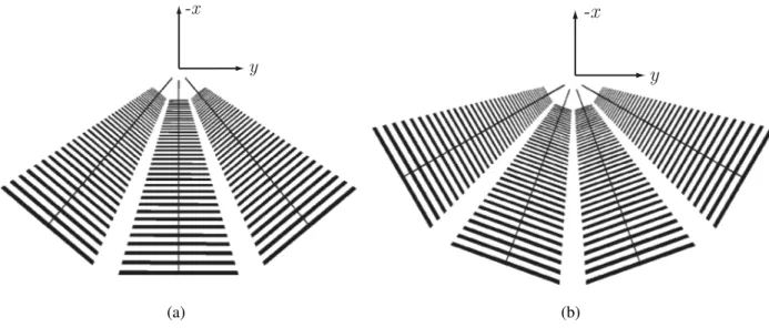
Fig. 1(a) shows a trapezoidal-tooth LP antenna, which is designed for broadband applications in the 300-800 MHz range [1]. The geometric growth factor of the antenna is τ = 0.95, which means that the two consecutive el-ements on the antenna are scaled versions of each other with a scale constant of 0.95. The arms of the antenna expand from the source location with an angle of 30◦,
and the 2 × 38 teeth are attached to the center strips with constant widths. The arms of the antenna are separated by an angle of 45o. Using the antenna in Fig. 1(a), a
2-element circular array of identical LP antennas is con-structed as depicted in Fig. 1(b), where the the antennas are separated by 40o. This way, it becomes possible to
feed the two antennas independently to steer the main beam and the overall structure is still log-periodic so that the array should also be nearly frequency-independent. Similar to the 2-element array in Fig. 1(b), we also con-struct 3-element and 4-element LP arrays as depicted in Fig. 2(a) and Fig. 2(b), respectively.
To analyze the LP arrays, the surfaces of the antennas
_____________________________________________________ Proc. ‘EuCAP 2006’, Nice, France
-x y z -x y (a) (b)
Figure 1. (a) Nonplanar trapezoidal-tooth LP antenna. (b) Circular array of two closely spaced LP antennas.
-x
y
-x
y
(a) (b)
Figure 2. Circular arrays of closely spaced LP antennas with (a) three elements and (b) four elements.
are modelled with perfectly conducting sheets. Then, the radiation problem is formulated by EFIE derived from the boundary condition for the tangential electric field. Expressing the scattered electric field in terms of the induced surface current J, we obtain EFIE in the exp (−iwt) convention as
ˆ t · Z S0 dr0G(r, r0) · J(r0) = i kηˆt · E inc(r), (1)
where ˆt is any tangential vector on the conducting
sur-face, Eincis the incident electric field created by the ex-citations of the antennas, k is the wavenumber, η is the characteristic impedance of the free space,
G(r, r0) = · I +∇∇ k2 ¸ g(r, r0) (2)
is the dyadic Green’s function, and
g(r, r0) = eik|r−r
0|
4π|r − r0| (3)
is the Green’s function for the three-dimensional Helmholtz equation.
In order to simultaneously discretize the geometry and EFIE, we expand the unknown surface current in a se-ries of Rao-Wilton-Glisson (RWG) [6] basis functions defined on small planar triangles as
J(r) = N
X
n=1
anbn(r), (4)
where anis the unknown coefficient of the nth basis
x y −40 −20 0 20 40 −40 −20 0 20 40 −40 −20 0 20 40 −40 −20 0 20 40 −40 −20 0 20 40 −40 −20 0 20 40 x y −40 −20 0 20 40 −40 −20 0 20 40 −40 −20 0 20 40 −40 −20 0 20 40 −40 −20 0 20 40 −40 −20 0 20 40 x y −40 −20 0 20 40 −40 −20 0 20 40 −40 −20 0 20 40 −40 −20 0 20 40 −40 −20 0 20 40 −40 −20 0 20 40 x y −40 −20 0 20 40 −40 −20 0 20 40 −40 −20 0 20 40 −40 −20 0 20 40 −40 −20 0 20 40 −40 −20 0 20 40 (400 MHz) (550 MHz) (700 MHz)
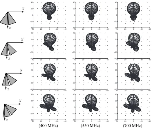
Figure 3. Normalized radiation intensity (in dB) of the 2-element array in Fig. 1(b) for different frequencies and various rotated orientations as shown in the first column. The directive gain is optimized in the −x direction by the GAs.
EFIE in (1) onto the RWG testing functions tm, we
ob-tain the matrix equation
N X n=1 ZmnE an= vmE, m = 1, ..., N, (5) where ZmnE = Z Sm drtm(r) · Z Sn dr0G(r, r0) · bn(r0) (6)
represents the matrix element, and
vE m= i kη Z Sm drtm(r) · Einc(r) (7)
represents the mth element of the excitation vector. In (6) and (7), Smand Snsymbolize the spatial supports of
the mth testing and nth basis functions, respectively. Iterative solution of the N × N matrix equation in (5) via MLFMA gives the coefficients for the expansion in (4). Then, the radiation intensity of the array is calculated as f (θ, φ) = k 2η2 4π ¯ ¯ ¯ˆθ ˆθ · F (θ, φ) + ˆφ ˆφ · F (θ, φ) ¯ ¯ ¯2, (8) where F (θ, φ) = Z S drJ(r) exp (−ik · r) = N X n=1 an Z S drbn(r) exp (−ik · r) (9)
represents the vector current moment. Since we desire to optimize the excitations of the antennas in the arrays, it is required to test a number of different values for the feeds. Although we employ GAs in order to reduce the number of trials, it is difficult to solve every radiation problem during the optimization. We therefore employ a superpo-sition technique so that the number of MLFMA solutions can be kept as low as the number of elements in the ar-ray. In each solution, we feed only one of the antennas with the excitation strength of unity. The vector current moment F (θ, φ) in (9) is then calculated and stored in the memory. We note that the solution by exciting one of the antennas in the array is different from the solution of a single antenna alone, since the former includes the mutual couplings between the antennas. Whenever it is required to test a set of values for the excitations, the vec-tor current moments are multiplied by the corresponding coefficients and superposed to obtain a single vector cur-rent moment for the whole array. Then, we evaluate (8) to calculate the radiation intensity of the array. We note that this procedure is applied at each frequency.
x y −40 −20 0 20 40 −40 −20 0 20 40 −40 −20 0 20 40 −40 −20 0 20 40 −40 −20 0 20 40 −40 −20 0 20 40 x y −40 −20 0 20 40 −40 −20 0 20 40 −40 −20 0 20 40 −40 −20 0 20 40 −40 −20 0 20 40 −40 −20 0 20 40 x y −40 −20 0 20 40 −40 −20 0 20 40 −40 −20 0 20 40 −40 −20 0 20 40 −40 −20 0 20 40 −40 −20 0 20 40 x y −40 −20 0 20 40 −40 −20 0 20 40 −40 −20 0 20 40 −40 −20 0 20 40 −40 −20 0 20 40 −40 −20 0 20 40 (400 MHz) (550 MHz) (700 MHz)
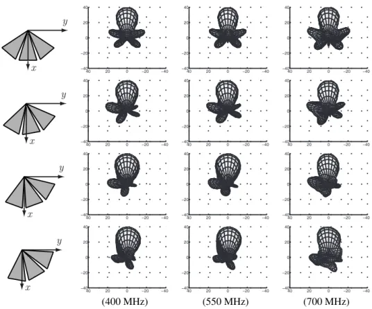
Figure 4. Normalized radiation intensity (in dB) of the 3-element array in Fig. 2(a) for different frequencies and various rotated orientations as shown in the first column. The directive gain is optimized in the −x direction by the GAs.
3. EMPLOYING GENETIC ALGORITHMS FOR BEAM-STEERING
In this work, we employ GAs to add beam-steering abil-ity to the LP arrays. Since it is desired to point the main beam in a specific direction, we choose the directive gain as the cost function of the optimization. The directive gain is defined as
D(θ, φ) = 4πf (θ, φ)
P (θ, φ) (10)
as a function of spherical coordinates (θ, φ), where
P (θ, φ) = Z 2π 0 Z π 0 f (θ, φ) sin θdθdφ (11) and f (θ, φ) represents the radiation intensity derived in (8). We employ GAs to optimize the excitations of the array elements that maximize the directive gain in (10). Such an optimization of the directive gain in some given (θ, φ) provides the steering of the main beam towards that direction. In addition, the radiation characteristic of the array is stabilized with respect to frequency and the array becomes more frequency-independent by the opti-mization.
GAs work on a pool of citizens, each of which repre-sents a trial combination of the optimization variables.
We employ a one-to-one map to convert the values repre-sented by each trial into a single lengthy word of binary numbers, called the chromosome. Each citizen also has a degree of success, which is simply the value of the cost function of the optimization, i.e., the directive gain at the optimization angle. We define the successful citizen as the set of excitations, which results in high directive gain. In the beginning of the optimization, the citizens are created randomly. The optimization is then continued as new generations are formed and the pool is modified progressively. Heuristically, as the new generations are produced and the pool evolves, the overall success of the population increases. In the extreme case, all the citizens are the same with the highest possible success after a number of generations. Then, the optimization is completed and any citizen gives the optimal values via an inverse mapping from the chromosome to the excitations. However, it is usually sufficient to interrupt the iterations after a number of generations and select the most suc-cessful citizen in the pool as the optimization result. In our optimizations for the LP arrays, we use pools with 20–30 citizens and keep the mutation rate for each digit of the chromosomes at about 5%. The limit for the number of generations is selected to be 50, i.e., we stop the iterations after the 50th generation. Therefore, the number of trials to complete the optimization is about 1000–1500. For the 3-element and 4-element LP arrays leading to large optimization spaces, the benefit gained
x y −40 −20 0 20 40 −40 −20 0 20 40 −40 −20 0 20 40 −40 −20 0 20 40 −40 −20 0 20 40 −40 −20 0 20 40 x y −40 −20 0 20 40 −40 −20 0 20 40 −40 −20 0 20 40 −40 −20 0 20 40 −40 −20 0 20 40 −40 −20 0 20 40 x y −40 −20 0 20 40 −40 −20 0 20 40 −40 −20 0 20 40 −40 −20 0 20 40 −40 −20 0 20 40 −40 −20 0 20 40 x y −40 −20 0 20 40 −40 −20 0 20 40 −40 −20 0 20 40 −40 −20 0 20 40 −40 −20 0 20 40 −40 −20 0 20 40 (400 MHz) (550 MHz) (700 MHz)
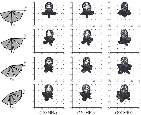
Figure 5. Normalized radiation intensity (in dB) of the 4-element array in Fig. 2(b) for different frequencies and various rotated orientations as shown in the first column. The directive gain is optimized in the −x direction by the GAs.
from GAs becomes essential compared to the brute-force approach that has prohibitively high computational cost.
4. RESULTS
Fig. 3 presents the normalized radiation intensity of the 2-element array in Fig. 1(b) for different frequencies and various rotated orientations as shown in the first column, i.e., 0o, 10o, 20o, and 30ofrom top to bottom. In all cases,
the directive gain is optimized in the −x direction by the GAs. This way, we test the array for a beam-steering ability in a 2 × 30orange considering the symmetry of
the array geometry. We observe that the GAs provide a main lobe consistently in the −x direction even though the array is rotated for 30o. However, it is obvious that
the side lobes become larger and quality of the radiation drops as the steering angle is increased. In Fig. 3, we also note that the radiation of the array looks similar for different frequencies, i.e., at 400 MHz, 550 MHz, and 700 MHz, and broadband operation is achieved.
For the 3-element and 4-element array in Fig. 2, the radiation patterns are depicted in Fig. 4 and Fig. 5, re-spectively. As the array is constructed by more elements, the beamwidth becomes narrower but more side lobes appear. In all cases for both arrays, the main beam is directed to −x direction and beam-steering is obtained in
the 2 × 30orange. In addition, the arrays provide
broad-band operation, which becomes relatively more difficult to satisfy for the 4-element array due to the increased mutual couplings between the antennas.
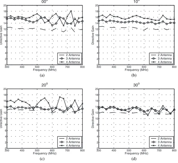
Finally, to compare the performances of the three arrays, Fig. 6 presents the directive gain in the −x direction for different orientations of the arrays. When the arrays are not rotated, Fig. 6(a) shows that 3-element and 4-element arrays give larger directive gains compared to the 2-element array. However, their gains are less stable with respect to frequency and oscillates more than the gain of the 2-element array. When the beam is steered for a small angle, such as 10o, more populous arrays still
provide larger directive gain for all frequencies. This is also true in average for higher angles of beam-steering. However, when the steering angle is further increased to 20o and 30o, 3-element and 4-element arrays cannot
provide higher directive gains compared to the 2-element array for some frequencies due to the oscillations.
5. CONCLUSION
Circular arrays of LP antennas are investigated in de-tail by employing a sophisticated electromagnetic sim-ulation environment, where the radiation problems are formulated by EFIE and they are solved iteratively
us-3000 400 500 600 700 800 2 4 6 8 10 12 14 16 18 20 Frequency (MHz) Directive Gain 00o 2 Antenna 3 Antenna 4 Antenna 3000 400 500 600 700 800 2 4 6 8 10 12 14 16 18 20 Frequency (MHz) Directive Gain 10o 2 Antenna 3 Antenna 4 Antenna (a) (b) 3000 400 500 600 700 800 2 4 6 8 10 12 14 16 18 20 Frequency (MHz) Directive Gain 20o 2 Antenna 3 Antenna 4 Antenna 3000 400 500 600 700 800 2 4 6 8 10 12 14 16 18 20 Frequency (MHz) Directive Gain 30o 2 Antenna 3 Antenna 4 Antenna (c) (d)
Figure 6. Directive gain in the −x direction for 2-element, 3-element, and 4-element arrays when the arrays are (a) not rotated, and when they are rotated for (b) 10o, (c) 20o, and (d) 30o.
ing MLFMA. Excitations of the elements of the arrays are optimized by employing GAs in order to add a beam-steering ability to the arrays. This way, we obtain both steerable main beam and frequency-independent radia-tion in 300-800 MHz range.
ACKNOWLEDGMENTS
This work was supported by the Scientific and Techni-cal Research Council of Turkey (TUBITAK) under Re-search Grant 105E172, by the Turkish Academy of Sci-ences in the framework of the Young Scientist Award Pro-gram (LG/TUBA-GEBIP/2002-1-12), and by contracts from ASELSAN and SSM.
REFERENCES
[1] ¨O. Erg¨ul and L. G¨urel, “Nonplanar trapezoidal-tooth log-periodic antennas: design and electromagnetic
modelling,” Radio Science, vol. 40, Oct. 2005. [2] ¨O. Erg¨ul and L. G¨urel, “Log-periodic antenna design
using electromagnetic simulations,” in Proc. IEEE
An-tennas and Propagation Soc. Int. Symp., vol. 1, 2003,
pp. 245–248.
[3] A. W. Glisson and D. R. Wilton, “Simple and efficient numerical methods for problems of elec-tromagnetic radiation and scattering from surfaces,”
IEEE Trans. Antennas Propagat., vol. AP-28, no. 5,
pp. 593–603, Oct. 1980.
[4] C.-C. Lu and W. C. Chew, “Multilevel fast multi-pole algorithm for electromagnetic scattering by large complex objects,” IEEE Trans. Antennas Propagat., vol. 45, no. 10, pp. 1488–1493, Oct. 1997.
[5] Y. Rahmat-Samii and E. Michielssen,
Electromag-netic Optimization by GeElectromag-netic Algorithms. New York:
Wiley, 1999.
[6] S. M. Rao, D. R. Wilton, and A. W. Glisson, “Electromagnetic scattering by surfaces of arbitrary shape,” IEEE Trans. Antennas Propagat., vol. AP-30, pp. 409–418, May 1982.