AN INVESTIGATION OF BASE ISOLATION Akbar Sheidaei HABASHI
Faculty of Engineering, Department of Civil, Islamic Azad University, Urmieh Branch, IRAN [email protected]
ABSTRACT: The effect of weak shear rigidity is important in the analysis of elastomeric bearings used for base isolation of buildings. In particular, the buckling load is low and the P-Δ effect is significant as compared to standard columns neglecting shear deformations. In this paper, a simple mechanical model accounting for both shear and flexural deformations is proposed to treat the P-Δ effect of elastomeric isolation bearings. With adequate choice of the model parameters, the simplified model agrees very well with an exact model in both static and dynamic cases. When applied to the experimental results for some natural rubber bearings, the model is found to describe with good accuracy the effects of axial load on the dynamic stiffness, the damping factor and the height reduction of bearings. A brief study of the post-buckling behaviour of elastomeric bearings using the simplified model is also presented.
Keywords: Base Isolation, Elastomeric bearing, Buckling, Post-buckling. Taban İzolasyonu Üzerine Bir İnceleme
ÖZET: Binaların taban izolasyonunda kullanılan elastomer yatağın analizinde zayıf kayma rijitliğinin etkisi çok önemlidir. Özellikle, burkulma yükü düşük olup P-∆ etkisi kayma deformasyonlarının ihmal edildiği standart kolonlara nazaran önemlidir. Bu makalede, elastomerik izolasyon yatakların P-∆ etkisini işlemek için hem kayma hem de eğilme deformasyonlarını nazara alan basit bir mekanik model önerilmiştir. Model parametrelerinin yeterli seçimi ile basitleştirilmiş model hem statik hem de dinamik durumlarda gerçek modelle iyi uyum göstermektedir. Tabii kauçuktan mamul yataklar için deney sonuçları tatbik edildiğinde modelin, eksenel yükün dinamik direngenlik üzerine etkileri, sönümleme faktörü ve taşıyıcı yüksekliğinde azalması üzerine doğru sonuçlar verdiği bulunmuştur. Ayrıca, basitleştirilmiş model kullanılarak elastomerik yatakların ileri-burkulma çalışması da takdim edilmiştir. Anahtar Kelimeler: Taban izolasyonu, Elastomer yatak, Burkulma, Sonraki burkulma.
1. INTRODUCTION
The base isolation method, an unconventional building design approach used for protection against earthquakes, has recently been a topic of interest in earthquake engineering. This approach recognizes the crucial fact that the earthquake motion is transmitted (KhodaBandehLou, 1999; 2000) to the building only through its base. Therefore the design task of building can be made easier if the transmission of earthquake-induced loads is
reduced at the base level by some means of isolation from the ground motion.
To date, many types of base isolation systems have been proposed, including the sliding system, roller bearing system, sleeved-pile system and elastomeric isolation system. The most practical system which has been adopted in several countries is the elastomeric isolation system, thanks to current technology in the manufacture of multilayered elastomeric bearings that can sustain large deformations. These isolation bearings are of the same general
2 A.S. HABASHI
form as those used in conventional bridge design for the relief of thermal and creep movements. However, isolation bearings are more slender than standard bridge bearings so as to achieve a low horizontal stiffness. The isolation bearings are thus weak in shear rigidity and expected to have a low critical (buckling) load, as compared to conventional structural elements. As a result, it is important to include the effect of axial load (or specifically, the P-Δ effect) in the dynamic analysis of buildings supported on elastomeric isolation bearings. This is especially so in view of the fact that, in practice, base-isolated buildings normally require the use of a large number of isolation bearings. (For example, a total of ninety eight natural rubber bearings are used in supporting the first base-isolated building in U.S.A-the Foothill Communities Law and Justice Center located at San Bernardino, California (KhodaBandehLou, 2002).) However, normally only several standard sets of bearings are designed, in order to reduce costs. Each set of bearings designed may therefore have to accommodate a considerable range of axial loads. Furthermore, in the event of a severe earthquake, the bearings undergo large displacements, and the overturning moment of the base-isolated building may also cause
significant increase in the axial loads on the bearings In the dynamic analysis of such cases, due consideration must be given to the P-Δ effect on bearing behaviour.
2. A SIMPLE MECHANICAL MODEL
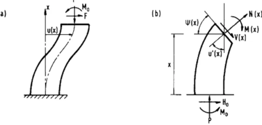
Elastomeric isolation bearings are normally modeled by the so-called Haringx column (Figure 1), with both shear deformation and flexural deformation taken into account. On the basis of Haringx's theory (KhodaBandehLou, 2003a), the influence of axial load on the static horizontal stiffness of rubber bearings has been studied analytically and experimentally (KhodaBandehLou, 2003b; 2003c). More recently, a viscoelastic P-Δ model for elastomeric isolation bearings has been constructed (KhodaBandehLou, 2005). A brief summary is given in the Appendix. This model is an exact one and reduces to the Haringx theory in the static case. Nevertheless, the exact model is not a convenient physical model that can be readily used in most structural analysis programs. For this reason, a simple mechanical model which has two internal degrees of freedom to represent the shear rigidity and flexural rigidity of the bearing is suggested here.
Figure 1. (a) Haringx column subjected to end loads. (b) Equilibrium and kinematics at an arbitrary cross section
Figure 2. (a) A simple mechanical model for elastomeric bearing.(b) Deformations due to applied end loads
Consider a rigid column of length L erected on a rigid plate which is resting on two frictionless rollers of negligible dimension (Figure 2). The rollers sit on another rigid plate and a horizontal spring restricts the relative displacement (s) between the top and bottom plates. The bottom plate is supported at a pivot and the relative rotation (θ) is constrained by a rotational spring. The stiffnesses of the rotational and horizontal springs are K1 (moment per radian) and K2 (force per unit length), respectively. A vertical compression load (P) and a horizontal load (F) are applied at the top end of the column. The horizontal displacement of the top end of the column is
θ
θ
cos
sin
s
L
U
=
+
(1)or, in the small displacement theory
s
L
U
=
θ
+
(2)If we neglect the shear deformation by letting K2 tend to infinity, the buckling load of the model is
K1/L. On the other hand, if we neglect the flexural deformation by letting K1 tend to infinity, the horizontal stiffness of the model is
K2L. To recover the results of these two special cases, we simply set
L
P
K
1=
E (3) andL
GA
K
=
s 2 (4) where PE= π2 EI/L2 is the Euler buckling load ofbearing neglecting shear deformation; GAs and EI are, respectively, the shear rigidity and
flexural rigidity of the bearing. Equilibrium taking into account the P-Δ effect gives
=
−
−
−
F
F
L
s
GA
P
P
P
P
s Eθ
(5) from which the solutions for θ and s can be readily obtained:)
1
(
1
P
P
P
P
P
GA
F
e e s−
−
+
=
θ
(6))
1
(
P
P
P
P
GA
F
s
e e s−
−
=
(7) where the following dimensionless loads are defined:4 A.S. HABASHI s
GA
P
P
=
, s E eGA
P
P
=
The horizontal stiffness of this model is thus
+
+
+
−
=
=
−)
1
(
)
1
(
1P
P
P
P
P
P
L
GA
u
F
K
e e s h (8) The height reduction at the top end is2
2θ
θ L
s
h
=
+
(9)The knowledge of height reduction is useful since it may be exploited to provide a fail-safe device which would prevent the structure from collapsing in case of bearing instability caused by large lateral displacement (KhodaBandehLou, 2006; Tarics, 1984).
The above solution is then extended to the dynamic case by considering a sinusoidal excitation F(t) = F0 exp(iωt) and the resulting displacement u(t) = u*exp(iωt) (The super-script * denotes a complex quantity). The model rigidities E1 and GAs are replaced by E*I = E1 (1 + i tanδ) and G*As = GAs(1 + i tanδ),
respectively, where δ is the loss angle of the elastomer. The term tanδ, known as the loss factor or loss tangent, is a measure of the ratio of energy lost to energy stored in a cyclic deformation. Replacing EI and GAs in Equation
(8) by their complex counterparts, we obtain the complex stiffness
+
+
+
−
=
≡
−)
1
(
)
1
(
1 * * * * * * 0 *P
P
P
P
P
P
l
A
G
u
F
K
e e s h (10) from which the dynamic stiffness and the loss factor of the bearing are evaluated, respectively, as * h dK
K
≡
and)
Re(
)
Im(
tan
* * h hK
K
=
φ
The height reduction corresponding to
F(t) = Focos(ωt) is given by
[
]
2
)
Re(
)
Re(
)
Re(
)
(
2 * * * iwt iwt iwte
A
l
e
e
S
t
h
+
=
θ
(11) where Re denotes the real part and)
1
(
1
* * * * *P
P
P
P
A
G
F
e s−
−
+
=
θ
)
1
(
* * * *P
P
P
P
A
G
F
S
e e s−
−
=
3. COMPARISON WITH THE EXACT MODEL For comparison purposes, an 8-in. natural rubber bearing (as described in section 4) is considered, with the assumed properties G = 0.69 MPa (0.1 ksi) and Pcr = 356 kN (80 kips).
The results for Kd and the maximum height
reduction hmax are presented in Figure 3(a) and
(b) respectively. It can be seen that the simplified model gives a slightly smaller stiffness than the exact model. The agreement for hmax between the simplified model and the exact model is good, except near the buckling load. As for the comparison of damping, we assume that the bearing has 10% equivalent viscous damping. The agreement for the damping factor sinΦ is excellent, as shown in Figure 3(c). For typical elastomeric isolation bearings, PE >> GAs, but P may be significantly larger than GAs so that P2/(PEGAs) cannot be neglected, we have where
s E cr
P
GA
P
≈
. The effect of the compression load in this case is two-fold-the loss part of K*h increases quadratically while the real part decreases quadratically with the compression load. In other words, the compression load not only reduces the stiffness, it also increases the energy dissipation {as a result of an increase in the phase angle between F(t) and u(t)}.
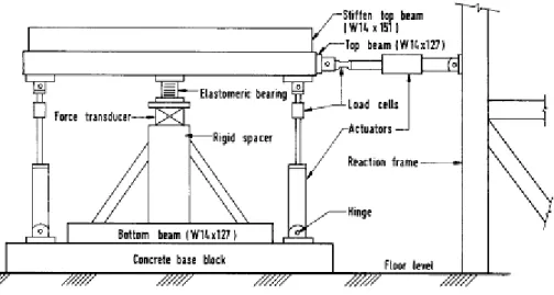
Figure 4. Test rig for sinusodial lateral loading of an elastomeric bearing subjected to compression load.
Figure 3. Comparison of analytical solutions for an 8-in. bearing: (a) Dynamic stiffness with no damping; (b) height reduction with no damping
at 1 inch displacement cycle; (c) damping factor with 10%-damping rubber. (Conversion factors
in all figures: 1 kip=4.45 kN, 1 in.=25.4 mm)
4. EXPERIMENTAL VERIFICATION
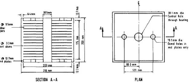
The experiments were carried out at the Earthquake Engineering Research Center, University of California, Berkeley, to show the applicability of the proposed simplified model. In the test rig shown in Figure 4, a rubber bearing specimen is subjected to a static vertical load and a sinusoidal horizontal load. The two vertical actuators are electronically controlled to maintain a specified constant compression load and zero differential displacement so as to produce the same boundary condition as assumed in the analysis. The test results of three different sets of natural rubber bearings are presented here. The first bearing (Bearing A) has fourteen layers of 9.5 mm thick rubber and thirteen 3.2 mm thick steel reinforcin plates (Figure 5). It is approximately a 20 cm cube with a circular hole of diameter 38 mm at the center. The second bearing (Bearing B) is approximately a 15 cm cube with no central hole. It has sixteen layers of 5.41 mm thick rubber and fifteen 1.6 mm thick steel plates. The third bearing (Bearing C) is the same as Bearing A except that it has a lead plug in the central hole to enhance damping. As the dynamic properties of rubber depend on the amplitude of motion the 'amplitude effect' (Haringx, 1948-1949) several series of tests were conducted at different displacement amplitudes. For each series of test results, the rubber properties were determined independently.
6 A.S. HABASHI
Figure 5. Cross section and plan view of natural rubber bearing (Bearing A). To use the simple mechanical model, we note the
following four parameters:
i) L is the combined height of the elastomer (rubber) layers and steel plates, not including) the top and bottom end plates.
ii) δ is the loss angle of the elastomer.)
iii) (GAs)eff is the effective shear rigidity of the
elastomer-steel bearing, as given by)
r eff s
L
L
GA
GA
)
=
(
(13)where Lr is the total thickness of all elastomer
layers. The scaling factor L/Lr is to account for
the presence of steel plates which are assumed to be rigid as compared to the elastomer, so that we can treat the bearing as a homogeneous column. iv) (EI)eff is the effective flexural rigidity of the
bearing. Due to the restricted lateral ) expansion of elastomer layer by bonding to steel plates,
(EI)eff can be many times the EI of unbonded
layers (Gent, 1964). If we assume
incompressibility for rubber (i.e. Poisson's ratio = 0.5), it can be shown that for a square shaped bearing, eff s eff
S
r
GA
EI
)
2
.
23
(
)
(
≈
2 2 (14)where S is the shape factor of rubber layer (defined as the ratio of the loaded area to the total force-free area) and r is the radius of gyration).
For the bearing with a central hole, the equivalent square bearing that has the same cross-sectional area and shape factor is used. Since L is known and (EI)eff is related to (GAs)eff
we need only two parameters, namely G and δ, to completely define the bearing ) characteristics for a fixed amplitude of motion. While data sheets for rubber are in some cases available from the manufacturers, the rubber used in the bearing may have somewhat different properties from the rubber used in the tests pertaining to the data sheets. It has been observed in past experiments that the bearing usually has a higher damping factor than the smaller rubber specimen used in the tests for obtaining the data sheets, but the reason for this is not fully understood. Also, the different curing conditions affect the shear modulus of rubber. For these practical reasons, G and δ are estimated from tests of the actual bearing specimens as follows: i) The value of δ is estimated from the initial portion of the damping curve, since theoretically
ɸ = δ at P = 0.
ii) The value of G at P=0 is similarly estimated from 1 2 1 2
12
)
tan
1
(
−
+
+
=
EI
GA
L
K
s dβ
δ
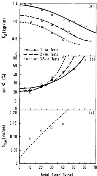
(15)Figure 6. Test results for Bearing A: (a) dynamic stiffness; (b) damping factor; height reduction. In Figure 6(a), the theoretical curves for the dynamic stiffness, Kd, based on the simplified
model are compared with the experimental data obtained for Bearing A. The comparison for the damping factor of the bearing is shown in Figure 6(b). It can be seen in both figures that the agreement between the experimental results and the simplified model is good. The quadratic variation of the damping factor of the bearing is clearly demonstrated by the experimental data and well described by the proposed model. The experimental results for the height reduction of 2.5 cm (1 in.) tests are too small to be reliable. Therefore, only the results for 7.6 cm (3 in.) and 12.7 cm (5 in.) tests are presented in Figure 6(c). It is seen that the simplified model gives a fairly good prediction of the height reduction.
Figure 7. Test results for Bearing B: (a) dynamic stiffness; (b) damping factor; height reduction. The results for Bearing B are presented in Figure 7. It is again seen that the simplified model can describe quantitatively the P-Δ effect on the variations in Kd and sinɸ. The prediction of the
height reduction also agrees fairly well with the experimental data. We treat Bearing C, which has a lead plug in it, as if it were homogeneous, without resorting to a more elaborate model to account for the elasto-plastic behaviour of the lead plug. The parameters determined are therefore considered to be some equivalent values for the rubber-lead composite bearing. The assumption of incompressibility is, however, no longer appropriate because of the presence of lead. Therefore (EI)eff is treated as an additional
8 A.S. HABASHI
estimated value of 6 as 19%, the values of (GAs)eff
and (EI)eff are found by best fitting the
experimental data in this case. Figure 8 shows the good fit of the test results by the simplified model for Kd and sinɸ, respectively. It is
interesting to note that the damping factor of the bearing went as high as when P was close to the critical load). The agreement for the height reduction is 96% ( somewhat less satisfactory near the buckling load.
Figure 8. Test results for Bearing C: (a) dynamic stiffness; (b) damping factor; height reduction. 5. POST-BUCKLING BEHAVIOUR
It has been shown that the proposed mechanical model, in spite of its simplicity as compared to the exact viscoelastic model, describes with good accuracy the changes in bearing stiffness, damping factor and height reduction due to the P-Δ effect. Although not shown here, the amplitude effect of elastomer can easily be accounted for by having non-linear springs whose stiffnesses are strain dependent. This model can also be used to study the
post-buckling behaviour, among other mechanics problems that are of interest in the design of elastomeric isolation bearings. First of all, we note that the simple mechanical model gives an exact buckling load (Pcr). Setting the numerator
term in Equation (8) to zero recovers the result as given in Equation (A8). Now, considering a large displacement formulation and letting F = 0 (Figure 2), we have the following equilibrium equations:
S
k
P
sin
θ
=
2 (16)θ
θ
θ
cos
)
1sin
(
L
S
k
P
+
=
(17)Eliminating s from the above equations and expressing in a non-dimensional form, we obtain the compression load at equilibrium:
θ
θ
cos
2
1
)
cot
4
1
(
2 1−
+
=
e SP
GA
p
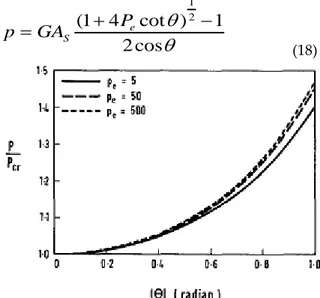
(18)Figure 9. Post-buckling equilibrium of bearings based on the simplified model
It is noted that elastomeric isolation bearings are generally quite squat and may be thought of as cubes of steel rubber laminates (KhodaBandehLou, 2003c). The shape factor (S) is typically in the range of 5-10. It can be shown that the Pe (i.e. PE/GAS) ratio is approximately
π2S2/6 and thus the Pe ratio is of the order of 10-100. The post-buckling equilibrium paths are plotted for Pe = 5, 50 and 500 in Figure 9, and are
6. CONCLUSIONS
A simple mechanical model with two internal degrees of freedom is proposed to account for the shear and flexural deformations of elastomeric isolation bearings. With the two internal parameters (K1 and K2) determined by matching the results with the exact solutions in two special cases, the model is found to give very good approximations of static stiffness and height reduction of the bearing. The model is then extended to treat the dynamic problems and shown to agree very well with the exact
model in terms of the damping factor of bearings. Experiments were carried out on three different rubber bearings and the simplified model is shown to give generally good correlations with the test results for dynamic stiffness and damping factor. The correlation for height reduction is fairly good except at high compresson loads. The model can also be used to study other mechanics problems of elastomeric bearings, among which the post-buckling behaviour is investigated here, and is found to be a stable one.
REFERENCES
A. G. TARICS, 1984, “The implementation of base isolation for the foothill communities law and justice center”, Report to the National Science Foundation and the County of San Bernardino. Reid and Tarics Associates, San Francisco.
A. N. GENT, 1964, “Elastic stability of rubber compression springs”, J. Mech. Engng Sci. 6, 318-326.
Ashkan – KhodaBandehLou, 1999, “Deformation and sinking of multistorey buildings system and especially skeleton frame structure”, Scientific – practical conference.
Ashkan – KhodaBandehLou, 2000 “Design of skeleton frame multistorey buildings, in seismology area”,
Scientific – practical conference.
Ashkan – KhodaBandehLou, 2002, “Design of ribbed plates, supported by the columns”, Works Scientific
– research institute of construction and architecture.
Ashkan – KhodaBandehLou, 2003a “Design of the beamless (flat) floor slabs studding their joint work with the skeleton frame concrete multistorey buildings” Design of the scientific works on
mechanic.
Ashkan – KhodaBandehLou, 2003b, “Design of vertical loading of skeleton frame buildings with beamless floor slabs" Technical Sciences.
Ashkan – KhodaBandehLou, 2003c, “Investigation of the work of beam and beamless floor slabs of multistoreyed buildings, erected in seismology area” II International Scientific – practical
conference. The significance of weakening of influence of emergency situations in stable development of the country.
Ashkan – KhodaBandehLou, 2005, “The investigation of the beam and beamless (flat) floor slabs in the multistoreyed buildings”, Technical journal.
Ashkan – Safar – KhodaBandehLou, 2006 “The investigation of the beam and griderless floor slabs in the multistorey buildings”, Scientific works.
J. A. HARINGX, 1948-1949, On highly compressive helical springs and rubber rods and their applications to free
mountings--Parts I, II and III. Philips Research Reports.
APPENDIX
AN EXACT VISCOELASTIC MODEL
Consider an elastic column of length I subjected to a compression load P, as shown in Figure 1. A horizontal force F is applied at the upper end, which is free to move horizontally with no
rotation of the cross section; the lower end of the column is fixed. We consider two kinematic variables-the lateral displacement of the center line, u(x), and the rotation of the cross section,ψ(x). With both shear and flexural deformations included, the following governing equations in terms of u and ψ can be derived:
10 A.S. HABASHI
x
H
M
x
Pu
x
u
GA
P
EI
s 0 0)
(
)
(
1
+
=
+
′′
+
(A1) 0)
(
)
(
1
H
x
P
x
GA
P
EI
s=
+
′′
+
ψ
ψ
(A2) where M0 and H0 are the end moment and end shear force, respectively, at x = 0. The boundary conditions are0
)
0
(
=
ψ
(A3)0
)
(
l
=
ψ
(A4)0
)
0
(
=
u
(A5)F
H
0=
−
(A6)A SIMPLE MODEL for ELASTOMERIC BEARINGS
An exact solution can be obtained by means of the mode superposition method, each mode being a solution of the stability problem. Satisfying Equation (A2), in which the right hand side is set to zero, and the boundary conditions (A3) and (A4), the mode shapes for ψ(x) are sinnπx/l (n= 1, 2, 3 . . . . ). For F #0, we simply let the solution to Equation (A2) be a superposition of all modes. Without going through the details, we present the following expression for the horizontal stiffness;
[
]
1 ,... 5 , 3 , 1 2 2 2 2)
1
(
)
1
(
8
1
− ∞ =
+
−
+
+
=
∑
∏
n e s hP
P
P
n
n
P
L
GA
K
(A7)Note that the buckling load is given by setting Kh = 0, and the lowest mode give