ScienceDirect
Materials Today: Proceedings 18 (2019) 1796–1802 www.materialstoday.com/proceedings
2214-7853© 2019 Elsevier Ltd. All rights reserved.
Selection and/or Peer-review under responsibility of INTERNATIONAL CONGRESS ON SEMICONDUCTOR MATERIALS AND DEVICES.
ICSMD-2017
Usage of T-Resonator Method at Determination of Dielectric
Constant of Fabric Materials for Wearable Antenna Designs
Özen Bayraktar, Dilek Uzer, S. Sinan Gültekin and Rabia Top
*Department of Electrical and Electronics Engineering, Selcuk University, Konya, 42075, Turkey.
*Department of Electrical and Electronics Engineering, Karamanoglu Mehmetbey University, Karaman, 70100, Turkey.
Abstract
In this study, determination of dielectric constants of fabric materials accurately by using T resonator method is aimed. Dielectric constant is one of the most important parameters that have a large effect on micro strip antenna performance. Small shifting at dielectric constant can cause huge alterations on electrical parameters of the antenna, especially at high frequencies. For this reason, a T resonator is designed on the wool felt fabric as the lower layer material at constant frequencies and the resonator dimensions are calculated. Using these calculated values, the finite element method is simulated with a High Frequency Electromagnetic Field Simulation (HFSS) as a resonator. After some size optimizations, the dielectric constant of the fabric was obtained correctly from the simulations. In order to validate the accuracy of the study and the values obtained, T resonator design on woolen felt material is manufactured and measurements of the resonator is realized with a vector network analyzer. Measurements of this resonator are compared with results from simulations and calculations. As a result, it has been shown that the dielectric constant of any fabric can be accurately determined using an easy, fast and inexpensive method and can be used in wearable micro strip antenna designs
© 2019 Elsevier Ltd. All rights reserved.
Selection and/or Peer-review under responsibility of INTERNATIONAL CONGRESS ON SEMICONDUCTOR MATERIALS AND DEVICES.
Keywords:T resonator; dielectric measurement; HFSS; fabric materials; woolen felt
* Corresponding author. Tel.: +90.332.223 20 42. E-mail address: [email protected]
1. Introduction
It is desired to be known the dielectric constant exactly in design of microwave and high frequency communication circuits. Dielectric constant is one of the most important parameters of materials for electronics designs. Most of system parameters of these circuits can be affected with a small alternation of the dielectric constant. In electromagnetic, the dielectric constant can be defined as the coefficient that measures the ability to store a load on a material. In other words, insulation constant is the measurement of how effects an electric field or an insulating media [1-5].
In wireless communication, micro strip antennas are used widely because of their advantages like being light, small, could be designed in different geometrical properties and could have various radiation patterns. They are also widely used in wearable technology because of the advantages illustrated. Devices and also antennas used for wearable technologies should have characteristic specifications like having low cost with a small, lightweight and compact configuration, low energy and resistant to environmental influences. To meet these properties, antenna models should be flexible and could easily added as a part of the clothes, when it is desired not to be detected because of privacy or seem more aesthetic, for these reasons the antennas designed on fabric material are highly preferred.
Fabrics are used as substrate materials in the antenna designs and that dielectric constant of fabric is one of the main parameters in antenna design. Dielectric constants, especially of fabric materials, are affected by using natural or synthetic material, weaving frequency of fabric, features of manufacturer firms etc. For the success of the communication, this constant should be known exactly [2-4, 6].
Designers study at microwave frequencies, have to known the characteristics of printed circuit board materials in order to attain exact functionality. These characteristics can be carried out with the micro strip T-resonator test method and micro strip ring resonator test method or a comparison of both methods for the same materials [7-9]. In these studies the dielectric constant could be found with a 0, 25% errors, while other literature methods have an error percentage of almost 10%.
In this study, it is focused on determination of dielectric constant of fabrics used in wearable antennas by using T resonator method. As antenna substrate material, woolen felt is chosen and at the beginning dielectric constant of the material is estimated to find the resonator’s parameters. Then Finite Element Method based simulation environment, HFSS (High Frequency Structure Simulator),is used for determining the resonator parameters and frequencies, also the estimated dielectric constant is true or not. Theoretical results are compared with the simulation results obtained. Then by choosing the resonator design with parameters who gives the closest frequency to be desired, the manufacturing and measurements of the resonator is realized. Finally, by comparing all results from measurements, calculations and simulations, dielectric constant of the fabric is successfully determined [6].
The paper is organized as follows; in Section 1 dielectric constant is reviewed and explained why it’s important in high frequency circuit designs. In Section 2, literature review of studies that measure the dielectric constant using different methods while T resonator method is briefly explained. Section 3 includes proposed method, calculations, simulation and measurements. Section 4 includes results of the experiments and the final value of dielectric value after comparing different measurements. Finally, Section 5 is a conclusion of the study.
2. Dielectric Measurement Methods
The measurement of complex dielectric properties of materials using at radio frequency devices are very important especially in the research fields, such as material science, microwave circuit and absorber designs, biomedical applications, etc. Dielectric measurement gives information about the electrical or magnetic characteristics of the materials, useful in many research and development fields [1-5, 11-13].
The measurement method must be selected as suitable for the material under test. Most common dielectric measurement methods in the literature are; transmission/reflection line method, open ended coaxial probe method, free space method and resonant method. There is a comparison between these methods and specifications of them are given in Table 1[1, 3].
Table 1. Comparison of Dielectric Measurement Methods. Measurement
Techniques Materials S-Parameters
Dielectric Properties
Transmission/Reflection Line Coaxial Line Waveguides
S11 S21
εr µr Open-ended Coaxial Probe Liquids
Biological Specimen Semi-Solids S11 εr
Free Space
High-Temperature Material Large Flat Solid
Gas Hot Liquids S11 S21 εr µr
Resonant (Cavity) Method
Rod Shade Solid Materials Waveguides Liquids Frequencies Q-Factors εr µr 2.1. T- Resonator Method
The micro strip T-resonator method is developed to provide numerous data points over a broad frequency range with a simple configuration and ease of fabrication and is used in defining the properties of different materials in the large frequency range from 1 to 20 GHz. In initial design from the literature and in this paper, the effects of external loading of the resonator due to the measurement system are not taken into account, and the equations used for discontinuities and loss components are not introduced.The T-resonator is composed of a simple T-pattern, which includes an open-end transmission stub and feed lines. The T-resonator resonates at odd integer multiplies of its quarter wavelength frequency.The basic idea behind determining the values of the dielectric constant with the T-resonator is to design a T-resonator structure for a specific main resonant frequency. The design is based on an estimated value of the dielectric constant. From (1), the length of open end of the resonator can be calculated [2-4]:
4 stb r eff n c L f e = (1) Where;
Lstb: The length of the open end of the resonator (mm),
n:The resonant coefficient of odd modes in the line, c:The speed of light in free space (mm/s)
fr: Resonant frequency (MHz)
εeff: Effective dielectric constant.
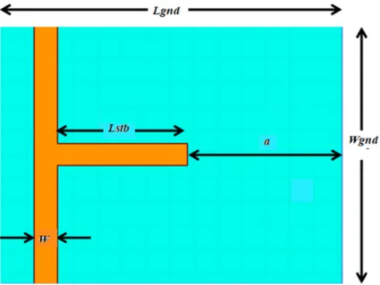
T resonator parameters in Figure 1 are explained as following:
Lgnd: The ground plane length,
Wgnd: The ground plane width,
W: The width of the feedline and open end of the resonator, a: The distance between the ground plane edge and the resonator
Fig. 1. T resonator design.
3. The Methodology
At the beginning of the study, the material for wearable antenna designs is determined a woolen felt. It has a thickness of 1,2 mm and the dielectric constant is estimated as 1,45 considering similar studies in the literature . By using this value, a T resonator is designed for n1=1 with 2400 MHz and n2=3 with 7200 MHz. The HFSS design is
shown in Figure 2[10].
3.1. Calculation
By using the Equations (2) and (1) in literature, for estimated εr_est value and desired frequency open-end length
of the resonators was calculated [2-4, 11-13].By micro strip feedline length, Equation (3) is used. The initial values of these parameters are found as shown in Table 2.
Table 2. Initial Parameters of T resonator from Calculation.
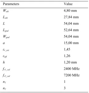
Parameters Value Wstb 4,80 mm Lstb 27,84 mm L Lgnd Wgnd a εr_est εeff h fr1_cal fr2_cal n1 n2 54,04 mm 52,64 mm 54,04 mm 15,00 mm 1,45 1,26 1,20 mm 2400 MHz 7200 MHz 1 3
At initial design, L was calculated from Equation (3). Wgnd was chosen as two times of L. Lgnd was chosen as
equal to total value of Lstb and 2×a.
= + 1 + 12 / for W/h>1 (2) and 0 2 eff c L f e = (3) 3.2. Simulation
Parameters calculated before were used for simulations. During simulations, Lstb value was swept between 10 and
45 mm with 1 mm steps, while at each step a value was swept between 10 and 30 mm with 1 mm steps. At the end of the sweeps, the best results were obtained and T resonator application was done by using these parameters. At each step, only one parameter sweep was realized for the purpose of exhibiting of which parameters has an effect and how on S21, clearly.
3.3 Measurement
When compared the simulated results with calculated results, we observed that the closest values of frequencies as fr1_sim = 2674 MHz and fr2_sim =7822 MHz while Lstb =27, 84 mm and a=13. When we take these results into account, the estimated value for dielectric constant at the beginning is not true. Again, by analyzing the simulation
results, fr1_sim= 2395 and fr2_sim=7075 MHz were found for Lstb =31 mm and a=14 mm. Whole calculation steps were retrospectively repeated and dielectric constants were found 1,014 for as n1=1 and1, 025 for n2=3, respectively. To validate these values, manufacturing then measurements of the resonators were realized with resonator parameters.
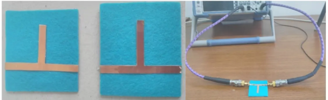
T resonator applications were realized for both designs. These designs are given in Figure 3. It is seen while applications, again, the greatest advantage of this method is that being simple, fast, cheap and easy. The resonators were manufactured in half an hour by handmade easily in our laboratory and the total cost was under 10 TL because all materials used for the method are few, cheap and easy found.
Fig. 3. Application of both T Resonators with initial and predicted designs.
During resonators processing the manufacturing, manually manufacturing led to the resonator and ground planes widths not to be as accurate as simulation which have a precision under 1% of mm. Therefore, the measurement results show small differences between simulated and measurements as presented in Table 3.
4. Results
Totally, 777 different sweeps were done for Lstb and parameters in simulations. For the chosen Woolen felt
fabric material, the dielectric constant is determined with high accuracy by comparing results from simulations, measurements and calculations.
It is obtained that a parameter does not change the frequency or dielectric constant value remarkably. So we can choose the smallest value of it, or the value which gives the best dB value of S21 for manufacturing. Frequencies from S21measurements with Vector Network Analyzer and corresponding dielectric constants are given in Table 3. Table 3. Comparison of Results from Calculation, Simulation and Measurements.
Lstb a fr1_cal fr1_sim fr1_mea fr2_cal fr2_sim fr2_mea εr_est1,2 εr_sim1 εr_sim2 εr_mea1 εr_mea2 27,84 13 2400 2674 2350 7200 7822 6355 1,450 1,004 1,005 1,079 1,018 31,00 14 2400 2395 2350 7200 7075 6850 1,450 1,017 1,013 1,154 1,032
*All dimensions in mm, all frequencies in MHz.
It’ s seen from Table 3 that dielectric constant values from simulation and measurement results are very close to each other. When a more precise manufacturing is made, closer results can be obtained. The difference between dielectric constants for different n values are almost same for both simulation and measurements, therefore it can be said that a coefficient can be added to the Equation (1).
5. Conclusion
In the study, a determination of the dielectric constant of woolen felt material that is aimed to be used for wearable antenna designs is realized by using T resonator method. By T resonator method, dielectric constant of fabric materials can be found easily and cheap. This method has a high accuracy value for εr which is a very
are simulated with HFSS, and the estimated dielectric constant value is compared with the value from simulations. Then, parameters that give the best and closest results are determined and this resonator is manufactured and measured. From all three kinds of results, the estimated dielectric constant is much bigger than the real value. In this manner, using a cheap and easy method, dielectric constant of the substrate material can be determined easily and accurately, so the antennas can be designed and operated with high accuracy.
References
[1] D. M. Pozar, Microwave Engineering, Wiley, USA, 2012.
[2] T. Rovensky, A. Pietrikova, K. Ruman, O. Kovac, Microstrip methods for measurement of dielectric properties in High Frequency area, Electronics Technology (ISSE), 2015 38th International Spring Seminar on , vol., no., pp.188-191, 6-10 May 2015 doi: 10.1109/ISSE.2015.7247987.
[3] http://www.mwrf.com/test-measurement/anritsu-lecroy-promote-partnership-edi-con-2017.
[4] K.P. Lätti, M. Kettunen, J.P. Ström, and P. Silventoinen, A Review of Microstrip T-resonator Method in Determination of Dielectric Properties of Printed Circuit Board Materials, Proceedings of IEEE Instrumentation and Measurement Technology Conference, 16-19 May, Ottawa, Canada, 2005, pp. 62- 66. ISBN 0-7803-8880-1.
[5] R. Garg, P. Bhartia, I. Bahl, A. Ittipiboon, Microstrip Antenna Design Handbook, MA, Norwood:Artech House, 2001. [6] Ö. Bayraktar, MS Thesis, Selçuk University Konya, Turkey, (2018)
[7] I. Waldron, Ring Resonator Method for Dielectric Permittivity Measurement of Foams, MS Thesis, Worcester Polytechnic Institute WORCESTER POLYTECHNIC INSTITUTE, England, (2006).
[8] P. Jankowski-Mihułowicz, W. Lichoń, Grzegorz Pitera, and M. Węglarski, Determination of the Material Relative Permittivity in the UHF Band by Using T and Modified Ring Resonators, INTL JOURNAL OF ELECTRONICS AND TELECOMMUNICATIONS, 2016, VOL. 62, NO. 2, PP. 129-134 Manuscript received August 22, 2015; revised February, 2016. DOI: 10.1515/eletel-2016-0017
[9] S. N. Dudorov, D. V. Lioubtchenko, J. A. Mallat, and A. V. Räisänen , Differential Open Resonator Method for Permittivity Measurements of Thin Dielectric Film on Substrate, IEEE TRANSACTIONS ON INSTRUMENTATION AND MEASUREMENT, VOL. 54, NO. 5,, OCTOBER 2005
[10] HFSS , www.ansys.com/HFSS.
[11]K. Agarwal, Y.X.Guo, and B. Salam, Wearable AMC Backed Near-Endfire Antenna for On-Body Communications on Latex Substrate, IEEE Tran. on Components, Packaging and Manufacturing Techn., Vol. 6, no. 3, March 2016, pp.346-358.
[12]G. Gonzalez, Microwave Transistor Amplifiers Analysis and Design, 2nd ed., Prentice-Hall, Upper Saddle River, NJ, 1997, Chapter 2. [13] I.J. Bahl and D.K. Trivedi, "A Designer's Guide to Microstrip Line" MicroWaves, May 1977, pp.174-182.