A Reflectarray Antenna Using Hexagonal Lattice
With Enhanced Beam Steering Capability
ORCUN KIRIS 1,2, KAGAN TOPALLI 1, (Senior Member, IEEE),
AND MEHMET UNLU 3, (Member, IEEE)
1TUBITAK Space Technologies Research Institute, 06800 Ankara, Turkey
2Department of Electrical and Electronics Engineering, Ankara Yildirim Beyazit University, 06760 Ankara, Turkey
3Department of Electrical and Electronics Engineering, TOBB University of Economics and Technology, 06560 Ankara, Turkey
Corresponding author: Mehmet Unlu ([email protected])
This work was supported by the TUBITAK Space Technologies Research Institute (TUBITAK UZAY) within the scope of 7I150800 (YADAS) Project.
ABSTRACT This paper presents a novel reflectarray antenna with enhanced beam steering capability. The reflectarray antenna is based on the hexagonal distribution of the unit cells on the antenna surface. The hexagonal topology changes the angle between the principal axes of the unit cell distribution, preventing the formation of the grating lobe, and improving the beam steering capability of the reflectarray antenna. To verify the proposed idea, two different sets of reflectarray antennas, which includes square and hexagonal lattice topologies with inter-element spacings of 0.52λ and 0.6λ, have been designed, fabricated, and measured at 8.23 GHz. The measurements of the all fabricated reflectarray antennas are in very good agreement with the simulations, and the comparison of the square and hexagonal topologies show that the beam steering capability can be improved by 50% for 0.6λ inter-element spacing by using a hexagonal topology. This improvement shows that a simple modification in the array configuration can be a viable solution for satellite and 5G communication applications that require increased beam steering capability.
INDEX TERMS Reflectarray, antenna array, hexagonal lattice, satellite communication, beam steering.
I. INTRODUCTION
High gain antennas are essential elements of most satel-lite communication systems and emerging 5G applications. Parabolic reflectors and array antennas are conventional solu-tions to meet these requirements. In recent years, a new type of antenna, namely ‘‘reflectarray antenna’’, has been introduced for such applications in order to alleviate the issues related with the conventional antenna solutions [1]. Reflectarrays provide a low-profile, low-weight, planar, and readily-deployable alternative, compared to bulky parabolic reflectors and arrays with complex feed networks. A reflec-tarray antenna is a planar array of printed radiating elements, i.e., unit cell elements, illuminated by a feed source, which is typically a horn antenna. The unit cells on the planar array surface are distributed in such a way that each unit cell compensates the path difference from the feed antenna to the unit cell position. The field received from the feed is reflected from the array surface forming an equiphase front The associate editor coordinating the review of this manuscript and approving it for publication was Xiu Yin Zhang.
in the desired direction. Moreover, reflectarray antennas offer the possibility of beam steering, like conventional phased arrays, but they eliminate the complexity and losses of the feed network; hence, they exhibit higher efficiency. Reflec-tarrays can provide solutions for many applications including earth stations, onboard antennas in satellite communication systems, micro-spacecraft missions, antennas for radars, and 5G applications [1]–[5].
Beam steering capability is also an important aspect for the high-gain antennas that are used for most of the satellite applications, where they illuminate the appointed geograph-ical area from Low Earth Orbit and Medium Earth Orbit satellites. The 5G applications also require high-gain anten-nas within a wide beam steering range in order to guarantee coverage availability [4], [5]. Therefore, the beam steering reflectarray antennas can be promising candidates for these applications [6]–[11].
The reflectarray studies in the literature are recently focused on efficient solutions based on some innovative tech-niques, architectures, and realizations. These recent stud-ies examine the effect of the unit cell element [12]–[18], 2019 IEEE. Translations and content mining are permitted for academic research only.
approach used for the design of the hexagonal unit cell. The proposed approach is based on the modification of the unit cell arrangement from the conventional square lattice to a hexagonal lattice. Then, four different reflectarray antennas that utilize the square and hexagonal lattices are analyzed using both analytical calculations and full-wave electromag-netic simulations, which are followed by the antenna fab-rication and measurements. Finally, a comparison between square and hexagonal lattice based reflectarrays in terms of the beam steering capabilities is presented. To the best of authors’ knowledge, the effect of lattice arrangement on the beam steering capability of the reflectarray antennas has been examined for the first time in the literature.
The paper is organized as follows: Section II presents the unit cell structures and simulation approach to design square and hexagonal lattice-based reflectarrays. Section III compares the performances of the designed reflectarrays in terms of phase distribution on the surface of the arrays, radi-ation patterns, gain bandwidths, and beam steering capability using the simulation and measurement results. Section IV concludes the paper.
II. UNIT CELL STRUCTURES
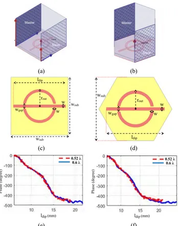
The design of a reflectarray antenna is implemented through the analysis of the unit cell, which is the building block of the reflectarray antenna. Phase design curve is an impor-tant parameter that characterizes the phase response of the unit cell with respect to a change in a physical parame-ter of the unit cell. The most practical method to extract the phase design curve of a unit cell is the infinite array approach, which is formed by replicating identical unit cells in two dimensions. The approach provides an opportunity for designing array structures by analyzing only a single element, i.e., unit cell with periodic boundary conditions, including the effect of mutual coupling between the ele-ments. The infinite array approach is implemented using a full-wave solver based on Finite Element Method (FEM) in ANSYS HFSS [24]. The periodic boundary conditions are implemented by master and slave boundaries on all respective sides of the unit cell elements. The fields on the ports are represented by a set of Floquet modes. Fig. 1-(a) and (b) show the Floquet mode excitation for square and hexagonal lattice-based unit cells, respectively. Fig. 1-(c) and (d) illustrates the physical parameters of the unit cells that are summarized in Table 1.
FIGURE 1. Unit cell simulation with Floquet mode configuration: (a) square and (b) hexagonal lattice. Physical design parameters of the unit cells: (c) square and (d) hexagonal lattice. Phase design curves for 0.52λ and 0.6λ structures: (e) square and (f) hexagonal lattice.
TABLE 1.Design parameters of the unit cells (mm).
We designed square and hexagonal lattice unit cells with two different inter-element spacing of 0.52λ and 0.6λ, where λ is the free-space wavelength at 8.23 GHz. The printed struc-ture that is given in [25] is called as the phi-shaped unit cell element. This element consists of a fixed-size split ring and a variable length dipole, which is designed at the operating frequency of 8.23 GHz on a 1.575 mm-thick RT/Duroid 5880 (εr = 2.2, tanδ = 0.0004) substrate. The dipole length is a variable parameter, providing a phase shift inserted by the unit cell while reflecting the incident wave. Fig. 1-(e) and (f) give the phase design curves for the square and hexagonal unit cells, respectively. These phase design curves indicate a phase range of more than 450◦for all unit cells.
III. SQUARE AND HEXAGONAL LATTICE-BASED REFLECTARRAYS
This section first presents a comparison between square and hexagonal lattice-based reflectarrays. In order to make a fair
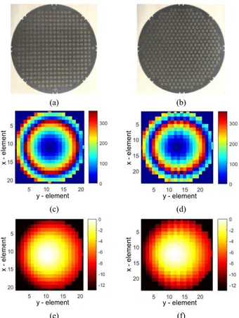
FIGURE 2. Fabricated reflectarray surfaces with 0.52λ inter-element spacing: (a) square and (b) hexagonal lattice. Phase distribution (degrees) on the surfaces: (c) square and (d) hexagonal lattice. Power intensity distributions (dB) on the surfaces: (e) square and (f) hexagonal lattice.
comparison and examine the effect of placement topology on the reflectarray performance, the unit cell type, offset angle of feed antenna, f/D ratio, reflected beam direction, and inter-element spacing are kept the same for both reflectarrays. Fab-ricated reflectarrays with an inter-element spacing of 0.52λ are shown in Fig. 2-(a) and (b). These square and hexagonal lattice arrays, having an aperture diameter of 39.8 cm, are composed of 317 and 367 unit cells, respectively. The arrays are illuminated by a horn antenna having an offset angle of 15◦ in y-direction to avoid feed blockage in boresight direction. In order to minimize the spill-over losses, f/D ratio is optimized to be 0.65 for an amplitude tapering around of −11 dB at the periphery of the array surface. The required amount of phase provided by each unit cell is calculated to give a particular phase distribution on the array surface for a desired beam direction. The phase distribution on the array surface that is required to achieve a reflected beam direction of 15◦ for square and hexagonal lattice-based reflectarray antennas are given in Fig. 2-(c) and (d), respectively. Power intensities on the unit cells, assuming a cosqfunction pattern to simulate the normalized power pattern of the feed horn, are illustrated in Fig.2-(e) and (f). The cosq pattern estimation is a method to determine the feed location and the aperture efficiency of the reflectarray designs [22].
FIGURE 3. Fabricated reflectarray surfaces 0.6λ inter-element spacing: (a) square and (b) hexagonal lattice. Phase distribution (degrees) on the surfaces: (c) square and (d) hexagonal lattice. Power intensity
distributions (dB) on the surfaces: (e) square and (f) hexagonal lattice.
FIGURE 4. The test fixture and setup used in the measurement.
A similar analysis is carried out for the 0.6λ inter-element spacing, where the yielding structures and results are pre-sented in Fig. 3. The reflected beam directions are 40◦ and 60◦, and the number of unit cells are 253 and 297 for square and hexagonal lattice-based reflectarrays, respec-tively. The aperture diameter for reflectarrays with 0.6λ inter-element spacing is 41.5 cm.
Fig. 4 shows the setup used in the anechoic chamber mea-surements. A test fixture is employed to precisely align the
FIGURE 5. Measured gain vs. frequency characteristics for square and hexagonal lattice-based reflectarrays with 0.52λ inter-element spacing.
Fig. 5 presents frequency dependency of the measured gains for the square and hexagonal lattice-based reflectarrays with 0.52λ inter-element spacing. In these simulations and measurements, the feed horn offset angle and reflected beam direction are set at 15◦ from the normal to the reflectarray surface. The results indicate that both reflectarray topologies yield almost the same gain, which is expected since the gain is mainly determined by the aperture size. The gain bandwidths are also similar for each array since the bandwidth is dom-inantly specified by the unit cell element employed. These results verify that the hexagonal topology can be readily used instead of the square topology.
Although the gain performances of square and hexagonal lattice-based reflectarrays are similar the hexagonal array topology can be used to obtain a lower phase error as it provides a densely-packed array with more unit cells on the reflectarray surface. Fig. 6-(a) and (b) give the directivity and gain patterns for square and hexagonal lattice-based reflectar-rays with 0.52λ inter-element spacing, respectively. There is a very good agreement between the measurements and simu-lations carried out at CST Studio Suite environment, which is computationally more efficient for such an electrically large problem. The overall efficiency, including the aperture and antenna efficiencies, is measured to be 65% for square and hexagonal lattice-based reflectarrays which shows that the reflectarray antennas were successfully designed.
In order to examine the beam steering capability of the square and hexagonal lattices, several reflectarrays are designed and simulated with an inter-element spacing of 0.6λ, where all reflectarrays have the feed horn offset angle of 15◦, but have gradually increasing, different main beam direc-tions, up to the point where they have a grating lobe. Here, each beam steering state is demonstrated using a
FIGURE 6. Fabricated Directivity patterns of the designed reflectarrays: (a) square lattice and (b) hexagonal lattice with 0.52λ inter-element spacing.
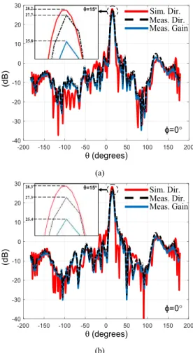
separately designed reflectarray antenna, which directs the main (reflected) beam to a specific angle. At this point, 5 square lattice-based and 7 hexagonal lattice-based reflec-tarrays are designed with main beam directions ranging from 0◦ to 40◦ and 0◦to 60◦ with 10◦ steps, respectively. Then, the square lattice and hexagonal lattice-based reflectarrays that are predicted to have grating lobes and have main beam directions of 40◦and 60◦are fabricated and measured, respec-tively. Fig. 7-(a) and (b) show the simulated and measured directivity patterns for the square and hexagonal lattice-based reflectarrays. The measurement results show a very good agreement with the simulations, which verify the improve-ment of the beam steering capability for the hexagonal topology.
One can see that a grating lobe appears for the square lattice-based reflectarray that is designed with main beam direction of 40◦, reducing the directivity by 5.46 dB with respect to the maximum directivity at 0◦. However, the grat-ing lobe appears for the hexagonal lattice-based reflectarray that is designed with main beam direction of 60◦, reducing the directivity by about 6.35 dB with respect to the maximum directivity at 0◦, increasing the allowable scan range by 50%.
FIGURE 7. Directivity patterns of the designed reflectarrays: (a) square and (b) hexagonal lattice. Grating lobe appears at 40◦and 60◦for the
square and hexagonal lattice indicating a significant improvement regarding the scan angle. Solid lines: simulations, dashed lines: measurements.
Here, it should also be noted for the hexagonal lattice-based reflectarray that the decrease in the directivity variation is less than 2.7 dB for the design that has a main beam direction of 50◦. These results clearly show that the scan angle range can be improved from 40◦to 60◦by employing a hexagonal lattice, instead of a square lattice in reflectarray antennas. The slight difference between the measurement and simulation results of 40◦ state is basically due to the formation of the grating lobe in this limiting state.
The reason behind the beam steering capability improve-ment can be explained considering the layout of the hexago-nal topology [26]. Fig. 8 shows the layouts of the both lattice types. The angle between the axes defining the periodic place-ment is 90◦in the square lattice, where it is 60◦in hexagonal lattice. This causes a change in the effective inter-element spacing (deff) in the horizontal axis, which is given as:
deff = dsinα
As a result of the hexagonal lattice, the effective distance in the horizontal axis is lower than that of the square lattice
FIGURE 8. Lattice types using in the reflectarray designs: (a) square, (b) hexagonal.
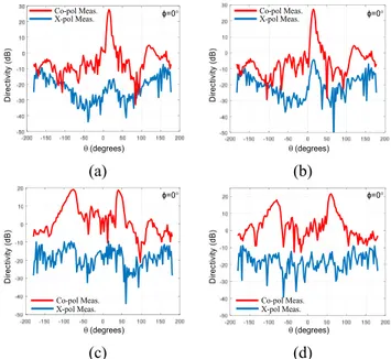
FIGURE 9. Measured co and cross polarization directivity patterns of the fabricated reflectarrays with 0.5λ: (a) square and (b) hexagonal lattice, and with 0.6λ: (c) square and (d) hexagonal lattice.
with the same inter-element spacing. This situation delays the grating lobe appearance for the reflectarray antennas that are designed to target higher beam steering angles, as observed in Fig. 7. In addition to that, the fabricated prototypes provide very good cross polarization performances as seen in Fig. 9. The cross-polarization discrimination of the fabricated and measured antennas is 31.7 dB for the main beam direction in the worst-case.
Taking advantage of this situation, one can design a reflectarray antenna with the inter-element spacing higher than 0.5λ, which increases the spacing required for the integration of additional components required for reconfiguration.
IV. CONCLUSION
This paper presented a reflectarray antenna based on a hexag-onal lattice placement of the unit cell, which also includes
significant advantage for the satellite and 5G communication applications, where the scan angle is a crucial parameter to be optimized in order to sustain a high-gain data link by means of electronic beam steering.
ACKNOWLEDGMENT
The authors would like to thank, Dr. Fahri Ozturk, Dr. Volkan Akan, and Suleyman Kose for fruitful discussions. The authors would also like to thank Dr. Mesut Gokten and Dr. Lokman Kuzu for their support.
REFERENCES
[1] J. Huang and J. A. Encinar, ‘‘Introduction to Reflectarray Antenna,’’ in Reflectarray Antennas, 1st ed. New York, NJ, USA: Wiley, 2008.
[2] J. A. Encinar, C. Tienda, M. Barba, E. Carrasco, and M. Arrebola, ‘‘Anal-ysis, design and prototyping of reflectarray antennas for space applica-tions,’’ presented at the Loughborough Antennas Propag. Conf. (LAPC), Loughborough, U.K., Nov. 2013.
[3] R. E. Hodges, D. J. Hoppe, M. J. Radway, and N. E. Chahat, ‘‘Novel deployable reflectarray antennas for CubeSat communications,’’ presented at the IEEE MTT-S Int. Microw. Symp. Dig., Phoenix, AZ, USA, May 2015.
[4] M. H. Dahri, M. Inam, M. H. Jamaluddin, and M. R. Kamarudin, ‘‘A review of high gain and high efficiency reflectarrays for 5G communications,’’ IEEE Access, vol. 6, pp. 5973–5985, Dec. 2017.
[5] M. H. Dahri, M. H. Jamaluddin, M. Khalily, M. I. Abbasi, R. Selvaraju, and M. R. Kamarudin, ‘‘Polarization diversity and adaptive beamsteering for 5G reflectarrays: A review,’’ IEEE Access, vol. 6, pp. 19451–19464, 2018.
[6] E. Carrasco, M. Barba, and J. A. Encinar, ‘‘X-band reflectarray antenna with switching-beam using PIN diodes and gathered ele-ments,’’ IEEE Trans. Antennas Propag., vol. 60, no. 12, pp. 5700–5708, Dec. 2012.
[7] O. Bayraktar, O. A. Civi, and T. Akin, ‘‘Beam switching reflectarray mono-lithically integrated with RF MEMS switches,’’ IEEE Trans. Antennas Propag., vol. 60, no. 2, pp. 854–862, Feb. 2012.
[8] S.-W. Qu et al., ‘‘Controlling dispersion characteristics of terahertz meta-surface,’’ Sci. Rep., vol. 5, Mar. 2015, Art. no. 9367.
[9] H. Yi, S.-W. Qu, K.-B. Ng, C. H. Chan, and X. Bai, ‘‘3-D printed millimeter-wave and terahertz lenses with fixed and frequency scanned beam,’’ IEEE Trans. Antennas Propag., vol. 64, no. 2, pp. 442–449, Feb. 2016.
[10] G.-B. Wu, S.-W. Qu, and S. Yang, ‘‘Wide-angle beam-scanning reflectar-ray with mechanical steering,’’ IEEE Trans. Antennas Propag., vol. 66, no. 1, pp. 172–181, Jan. 2018.
[11] P. Nayeri, F. Yang, and A. Z. Elsherbeni, ‘‘Bifocal design and aper-ture phase optimizations of reflectarray antennas for wide-angle beam scanning performance,’’ IEEE Trans. Antennas Propag., vol. 61, no. 9, pp. 4588–4597, Sep. 2013.
[12] H. Hasani, M. Kamyab, and A. Mirkamali, ‘‘Broadband reflectarray antenna incorporating disk elements with attached phase-delay lines,’’ IEEE Antennas Wireless Propag. Lett., vol. 9, no. 3, pp. 156–158, Mar. 2010.
Trans. Antennas Propag., vol. 53, no. 3, pp. 820–825, Mar. 2007. [18] L. Li et al., ‘‘Novel broadband planar reflectarray with parasitic dipoles for
wireless communication applications,’’ IEEE Antennas Wireless Propag. Lett., vol. 8, pp. 881–885, Jul. 2009.
[19] K. Karnati, S. Ebadi, and X. Gong, ‘‘Effects of inter-element spacing on mutual coupling and resonant properties in reflectarray unit cell design,’’ presented at the IEEE Radio Wireless Symp., Santa Clara, CA, USA, Jan. 2012.
[20] D. G. Kurup, M. Himdi, and A. Rydberg, ‘‘Design of an unequally spaced reflectarray,’’ IEEE Antennas Wireless Propag. Lett., vol. 2, pp. 33–35, 2003.
[21] M. W. Niaz, Z. Ahmed, and M. B. Ihsan, ‘‘Performance comparison of different aperture shapes for microstrip reflectarray,’’ presented at the 5th German Microw. Conf., Ilmenau, Germany, Mar. 2012.
[22] A. Yu, F. Yang, A. Z. Elsherbeni, J. Huang, and Y. Rahmat-Samii, ‘‘Aper-ture efficiency analysis of reflectarray antennas,’’ Microw. Opt. Technol. Lett., vol. 52, no. 2, pp. 364–372, Feb. 2010.
[23] P.-H. Wu and S.-Y. Chen, ‘‘Design of beam-steerable dual-beam reflec-tarray,’’ presented at the IEEE Int. Symp. Antennas Propag., USNC/URSI Nat. Radio Sci. Meeting, San Diego, CA, USA, Jul. 2017.
[24] Online Help, Master and Slave Boundaries, Version 15, ANSYS, New York, NY, USA, 2013.
[25] S. Oh, ‘‘Broadband reflectarray composed of gap coupled elements with linear phase response,’’ Microw. Opt. Technol. Lett., vol. 59, no. 5, pp. 1045–1047, May 2017.
[26] T. A. Milligan, ‘‘Arrays,’’ in Modern Antenna Design, 2nd ed. New York, NY, USA: Wiley, 2008.
ORCUN KIRIS was born in 1987. He received the B.Sc. degree in electrical and electronics engineering from Erciyes University, Kayseri, Turkey, in 2011, and the M.Sc. degree in electri-cal and electronics engineering from Middle East Technical University(METU), Ankara, Turkey, in 2014. He is currently pursuing the Ph.D. degree from Ankara Yildirim Beyazit University. He is currently a Senior Research Scientist with the TUBITAK Space Technologies Research Institute, which is the leading institute in Turkey in the implementation of LEO and GEO Satellites. His current research interests include reflectarray antennas, microstrip antennas for GPS applications, microwave components and anten-nas using substrate integrated waveguides, and microwave filters.
He was a recipient of the Best Poster Presentation Award, in 2015 given by the Department of Electrical and Electrical and Electronics Engineering, METU, at the 2015 EEE Graduate Research Workshop.
KAGAN TOPALLI (S’00–M’01–SM’13) was born in 1979. He received the B.S. and Ph.D. degrees in electrical and electronics engineering from Middle East Technical University (METU), Ankara, Turkey, in 2001 and 2007, respectively, where he was a Research Assistant with Depart-ment of Electrical and Electronics Engineering, METU, from 2001 to 2007. From 2007 to 2010, he was a Research Engineer with the MicroElec-troMechanical Systems (METU-MEMS) Center. He was also a Postdoctoral Researcher with the ElectroScience Laboratory, The Ohio State University, from 2010 to 2012. He was also a Faculty with the Department of Electrical and Electronics Engineering, TED University, Ankara, Turkey. He was also a Faculty with National Nanotechnology Research Center, Institute of Materials Science and Nanotechnology, Bilkent University. He is currently a Chief Research Scientist with the TUBITAK Space Technologies Research Institute, which is the leading institute in Turkey in the implementation of LEO and GEO Satellites. He has also conducted research on the development, characterization, and integration of novel RF MEMS structures for RF front ends at microwave and millimeter-wave reconfigurable antennas, phased arrays, micromillimeter-wave packaging, and microfabrication technologies. His current research interests include THz sensors and THz imaging systems. He received the METU Thesis of the Year Award, in 2007 for his Ph.D. dissertation, which was awarded by the Prof. Mustafa N. Parlar Education and Research Foundation. He received the Union of Radio Science-International (URSI) Young Scientist Award, in 2011. He received the Research Incentive Award, in 2013 given by the Prof. Mustafa N. Parlar Education and Research Foundation. He is the Co-Advisor to the recipient of the METU Thesis of the Year Award, in 2015.
MEHMET UNLU (S’00–M’11) received the B.Sc., M.Sc., and Ph.D. degrees in electrical and electronics engineering from Middle East Techni-cal University (METU), Ankara, Turkey, in 2001, 2003, and 2009, respectively. He was a Postdoc-toral Researcher with the METU-MEMS Center, in 2009. He served as a Research Scientist with Cornell Nanoscale Science and Technology Facil-ity, Ithaca, NY, USA, from 2009 to 2011, while he was with Utah State University, Logan, UT, USA. He joined the University of Michigan, Ann Arbor, MI, USA, in 2011, as a Postdoctoral Research Fellow. From 2012 to 2018, he served as a Faculty Member with Ankara Yildirim Beyazit University. He is currently serving as a Faculty Member with the TOBB University of Economics and Technology, Ankara. His current research interests include terahertz components, plas-monics, optoelectronics, MEMS, and reconfigurable circuits and antennas for microwave, and millimeter-wave applications.
Prof. Unlu received the The Scientific and Technological Research Coun-cil of Turkey (TUBITAK) Ph.D. Scholarship, from 2003 to 2009, the Prof. Mustafa N. Parlar Education and Research Foundation-METU Thesis of the Year Award, in 2009 for his Ph.D. dissertation, the Best Student Paper Award (2nd place) in International Symposium on Antennas and Propagation and the Best Student Paper Award (3rd place) in International Microwave Symposium, in 2013, the Prof. Mustafa N. Parlar Education and Research Foundation Research Encouragement Award, in 2013, the International Union of Radio Science (URSI) Young Scientist Award, in 2014, and the Turkish Academy of Sciences Outstanding Young Scientist Award, in 2015.