FREE VIBRATION ANALYSIS OF AN AIRCRAFT WING BY CONSIDERING AS A CANTILEVER BEAM
1Ali DEMİRTAŞ, 2Meral BAYRAKTAR
1, 2 Department of Mechanical Engineering, Mechanical Engineering Faculty, Yildiz Technical University, Besiktas, 34349 Istanbul, Turkey
1[email protected], 2[email protected]
(Geliş/Received: 25.08.2017; Kabul/Accepted in Revised Form: 02.03.2018)
ABSTRACT: The present paper presents the modal analyses of a NACA 4415 airfoil profiled wing. Theoretical and numerical calculations are performed by considering the aircraft wing as a cantilever beam. The model is created and modal analyses are performed by using commercially available packages of SolidWorks and Ansys, respectively. The natural frequencies and the related mode shapes are obtained. The results of theoretical calculations are compared with the numerical modal analyses. The study has a conclusion that an aircraft wing can be considered as a cantilever beam that by ignoring the whole forces on the aircraft (except for gravity).
Keywords: Airfoil, Wing, Cantilever Beam, Modal Analysis
Ankastre Kiriş Olarak Düşünülen Bir Uçak Kanadının Serbest Titreşim Analizi
ÖZ:
Bu çalışmada NACA 4415 profiline sahip uçak kanadının modal analizi sunulmuştur. Uçak kanadı
bir ankastre kiriş olarak düşünülerek teorik ve nümerik hesaplamalar gerçekleştirilmiştir. Kanadın modellenmesi ve modal analizi ticari paket programları SolidWorks ve Ansys ile yapılmıştır. Analiz sonucunda uçak kanadı modelinin doğal frekansı ve buna bağlı mod şekilleri elde edilmiştir. Teorik hesaplar neticesinde elde edilen sonuçlar nümerik modal analiz sonuçları ile karşılaştırılmıştır. Çalışmadan elde edilen sonuç, eğer yer çekimi kuvveti hariç diğer tüm kuvvetler ihmal edilirse, uçak kanadının ankastre bir kiriş olarak değerlendirilebileceği yönündedir.Anahtar Kelimeler:Ankastre kiriş, Kanat, , Modal analizi, Uçak kanadı.
INTRODUCTION
The modal analysis is a common method used to investigate dynamical behaviors of mechanical structures under the dynamics excitation. Emitted noise reduction from the system to the environment is enabled by the modal analysis. It helps finding out the reasons of vibrations which cause damage on the system and used for reducing it. In short, one can improve the performance of a system by using modal analysis method. Two primarily known methods of modal analysis are the numerical modal analysis and the experimental modal analysis. The mathematical model is derived from the measurement input data, which is handled by the experimental modal analysis. The modal is constructed from two different levels of analysis and the primary part is used for determining the curve FRF (Ewins, 2000). FRF frequency response function is a mathematical representation of the relationship between the input and the output of a system.
The free vibration analysis of analysis of an aircraft wing is one of the hardest problems to deal with in the process of designing an aircraft. A fundamental aspect in examining gust responses and aeroelastic phenomena is to investigate the natural frequencies and modes. The wings of an aircraft are usually consisted of thin-walled, non-uniform and arbitrary shaped structures which usually have sweep and dihedral angles and are tapered. These properties come with complicated effects that require sophisticated structural modeling. There are three different models that can be used for structural analysis of an aircraft wing. These models are consisted of “one-dimensional (beams), two-dimensional (plates, shells) and three-dimensional (solids)’’. One of the main advantages of one-dimensional model is that it requires less computational effort compared to the analysis of shells or solids. Euler-Bernoulli and Timoshenko models can be given as well-known examples to classical beam models. The last one includes transverse shear-deformation and rotary inertia effect. As the non-classical effects increase, the classical beam models become obsolete due to their feasibility. Non-classical effects in a wing structure are usually caused by in and out of plane, warping, twisting, bending-torsion coupling, and higher-order shear effects, among others (Carrera et al., 2012).
Free vibration analysis of beams has been extensively investigated by many researchers since the beams are fundamental models for the structural elements of many engineering applications. Free vibration analysis on elastic foundation or Winkler foundation have been studied by Thambiratnamt and Zhuge (1995), Ozturk and Coskun (2013) Kaçar et al.(2011). Nirmall and Vimala (2016) has investigated the vibration characteristics of beams made up of three different materials such as aluminum, brass, mild steel with respect to different parameters by theoretical and analytical method by using ansys software. They have reported that the natural frequency increases with decreases in thickness for each material.
Jaworski and Dowell (2008) have investigated the flexural-free vibration of a cantilevered beam with multiple cross-section steps theoretically and experimentally. They have compared the experimental results against Euler–Bernoulli beam theory solutions from Rayleigh–Ritz and component modal analyses, as well as finite element results using the commercial package ANSYS.
Amarendra and Rapuri (Amarendra and Rapuri, 2016) performed dynamic analysis of a doubly tapered and twisted beam (a geometrical approximation of a blade) and validated values of natural frequencies with the results of Gupta and Rao (Gupta and Rao, 1978). They also performed computational fluid dynamics (CFD) analysis to determine the lift and drag forces, their magnitude and directions on the blade. The obtained results of CFD analysis was used to conduct a stress analysis in ANSYS workbench by considering the designed geometry. These stresses were used for repetitive cycle for a fatigue analysis performed in the same workbench module.
Rajappan and Pugazhenthi (Rajappan and Pugazhenthi, 2013) have studied bending finite element analysis (FEA) of monocoque laminated composite aircraft (subsonic and supersonic) wing using ANSYS by considering various airfoil thickness and ply angles. The physical structure modeled was a shell aircraft wing of airfoil cross section NACA 4412 series with fiber laminated composite structure.
Erdener and Yaman (Erdener and Yaman, 2003) investigated the static and the dynamic characteristics of an aircraft wing in order to see the effects of probable internal fuel and the external stores on the dynamic characteristics by using MSC/PATRAN and MSC/NASTRAN. It was concluded that the natural frequencies for the 1st and 4th modes decrease about 66% rate in the case of full fuel and considering all external forces.
Khadse, N.A. and Zaweri, (Khadse and Zaweri, 2015) studied on the modal analyses of an aircraft wing that was considered as a cantilever beam. The structure of the aircraft consisted of NACA 64A215. The computer aided model (CAD) model of the wing was developed by using PROE 5.0 and modal analysis was carried out by means of ANSYS WORKBENCH 14.0. The six- modes of vibration were obtained as a result of theoretical and numerical studies
Lengvarský et al. (Lengvarský et al., 2013) carried out modal analyses on titan cantilever beam. They obtained mode shapes and natural frequencies by ANSYS and SolidWorks with numerical formulation
of the direct solver including the block Lanczos method as 94.02 [Hz], 207.58 [Hz], 324.32 [Hz], 570.47 [Hz], 823.64 [Hz].
In the present study, natural frequency and mode shapes of an aircraft wing were obtained by considering the wing as a cantilever beam. The wing model was created in SolidWorks by selecting the airfoil profile as NACA 4415. The model, then was simulated in ANSYS by applying proper boundary conditions to perform numerical modal analyses. The results of numerical modal analysis were compared with the results of theoretical approach of cantilever beam.
THEORETICAL CALCULATION
For a cantilever beam shown in Figure 1, the natural frequency for each mode was calculated from Euler-Bernoulli Beam Theory’s natural frequency equations (Eq.1,2,3) (Rao, 2011):
Figure 1. Cantilever beam.
𝜔𝑛= (𝛽𝑛𝐿)2√𝐸𝐼
𝑚𝐿4 (1)
where E (Pa) is Young Modulus, I (kg/m-2) is moment of inertia, m (kg/m) is mass per unit length, L
(m) is length. βnL is obtained by means of Eq.2 and Eq.3;
𝑑2 𝑑𝑥2{𝐸𝐼 𝑑2𝑌(𝑥) 𝑑𝑥2 } = 𝜔2𝑚(𝑥)𝑌(𝑥) (2) 𝛽4=𝜔2𝑚 𝐸𝐼 (3)
The magnitudes of (𝛽𝑛𝐿) are given in Table 1:
Table 1. Magnitude of (βnL)(𝑅𝑎𝑜, 2011). n (𝜷𝒏𝑳) 1 1,8751 2 4,69409 3 7,8539 4 10,99557 5 14,1372 6 17,279
The span wise bending stiffness distribution EI(z) (Pa.kg/m-2) along the primary axis of loading is
required to calculation of the vertical deflection of a wing. E (Pa) is a simple scaling factor for a uniform wing made of solid material. The moment of inertia of the airfoil cross-sections about the bending axis-x (called the bending inertia), is related 𝑌𝑢(𝑥) and 𝑌𝑙(𝑥) as shown in Figure 2. Both the area 𝐴 (m2) and total
bending inertia 𝐼 (kg/m-2) are the integrated contributions of all the infinitesimal rectangular sections,
each 𝑑𝑥 (wide) and 𝑌𝑢− 𝑌𝑙 (height). The inertia of each such section was appropriately taken about the
neutral surface position 𝑦̅ defined for the entire cross section (MIT Open Courseware).
Figure 2.Quantities for determining and estimating the bending inertia of an airfoil section) (MIT OpenCourseWare).
The corresponding equations are provided below (Eq.4-Eq.10). 𝐴 = ∫ (𝑌𝑢− 𝑌𝑙)𝑑𝑥 𝑐 0 (4) 𝑦̅ =1 𝐴∫ 1 2 𝑐 0 (𝑌𝑢 2− 𝑌 𝑙2) (5) 𝐼 = ∫0𝑐13[(𝑌𝑢− 𝑦̅)3− (𝑌𝑙− 𝑦̅)3]𝑑𝑥 (6) 𝑡 = 𝑚𝑎𝑥{𝑌𝑢(𝑥) − 𝑌𝑙(𝑥)} (7) ℎ = 𝑚𝑎𝑥{[𝑌𝑢(𝑥) + 𝑌𝑙(𝑥)]/2} (8) 𝐾𝐴← 1 𝑐2𝜏𝐴 ∫ [𝑌𝑢(𝑥) − 𝑌𝑙(𝑥)] 𝑐 0 𝑑𝑥 (9) 𝐾𝐼← 1 𝑐4𝜏(𝜏2+𝜀2)∫ 1 3[(𝑌𝑢− 𝑦̅) 3− (𝑌 𝑙− 𝑦̅)3] 𝑐 0 𝑑𝑥 (10)
But there are approximate values for KI and KA for most common airfoils as KI=0.036 and KA=0.6. A (m2) and I (kg/m-2) can be calculated as given in Eq.11 and Eq.12, respectively. 𝐴 ≅ 𝐾𝐴𝑐𝑡 (11)
𝐼 ≅ 𝐾𝐼𝑐𝑡(𝑡2+ ℎ2) (12)
Theoretical Analyses of NACA4415 Profiled Wing
The calculations of area and moment of inertia for NACA 4415 profiled wing were performed by getting the data from Airfoil Tools. The chord length and wing length was selected as 1 m and 5 m, respectively while the material was considered as Aluminium Alloy 6061.
For the calculation of Eq.7 and Eq.8 from airfoil data of NACA 4415, the .dat file was imported in to Microsoft Excel and it was organized and presented in Table 2.
Table 2.Organized columns from the data of airfoil profile 𝑥 𝑌𝑢(𝑥) 𝑌𝑙(𝑥) 𝑌𝑢(𝑥) − 𝑌𝑙(𝑥) [𝑌𝑢(𝑥) + 𝑌𝑙(𝑥)]/2 1 0 0 0 0 0,99893 0,00039 -0,00011 0.0005 0.00014 0,99572 0,00156 -0,00042 0.00198 0.00057 0,99039 0,00349 -0,00092 0.00441 0.001285 0,98296 0,0061 -0,00156 0.00766 0.00227 0,97347 0,00932 -0,00227 0.01159 0.003525 0,96194 0,01303 -0,00297 0.016 0.00503 0,94844 0,01716 -0,00364 0.0208 0.00676 0,93301 0,02166 -0,00431 0.02597 0.008675 0,91573 0,02652 -0,00502 0.03154 0.01075 0,89668 0,03171 -0,00583 0.03754 0.01294 0,87592 0,03717 -0,00674 0.04391 0.015215 0,85355 0,04283 -0,00775 0.05058 0.01754 0,82967 0,04863 -0,00886 0.05749 0.019885 0,80438 0,05453 -0,01006 0.06459 0.022235 0,77779 0,06048 -0,01136 0.07184 0.02456 0,75 0,06642 -0,01277 0.07919 0.026825
After MAX command was applied to the columns named 𝑌𝑢(𝑥) − 𝑌𝑙(𝑥) and [𝑌𝑢(𝑥) + 𝑌𝑙(𝑥)]/2 rows, 𝑡
(m) and h (m) values were determined as; 𝑡=𝜏=0,14994 m and h=𝜀=0,040095 m Substituting the obtained results in Eq.11; 𝐴≅𝐾𝐴𝑐𝑡=𝐾𝐴𝑐2𝜏=0,6×12×0,14994=0,089964 [m2]
Moment of inertia was obtained from Eq.12;
𝐼≅𝐾𝐼𝑐𝑡(𝑡2+h2)=𝐾𝐼𝑐4𝜏(𝜏2+𝜀2)=0,036×14×0,14994×(0,149942+0,0400952)=0,00013003187461173 [m4]
According to material selection of wing (Aluminum Alloy 6061), following parameters were used;(MatWeb ASM Aeurospace Specification Metals)
𝐸=69×109 [Pa]
𝐼=0,00013003187 [m4]
𝑚=𝜌×𝐴=2700×0,089964=242,9028 [kg/m] 𝐿=5 [m]
So, the natural frequencies were obtained as; ω𝑛f = (𝐵𝑛L)2√ EI
𝑚𝐿4= (𝐵𝑛L)2√
(69x109×0,00013003187)
242,9028×54 =
(𝐵𝑛L)2× 7,6876
As a result, the natural frequency of each mode which is obtained by using ω𝑛f = (𝐵𝑛L)2× 7,6876 was presented in Table 3.
Table 3. Natural frequency results
𝐵
𝑛𝐿
𝜔
𝑛𝑓 [rad/sec] 𝑓
𝑛𝑓 [Hz]
1 1.8751 27,0296 4,301895 2 4.69409 169,3923 26,95962 3 7.8539 474,2 75,47127 4 10.99557 929,4505 147,9266 5 14.1372 1536,447 244,5331 6 17.279 2295,239 365,2987 MODAL ANALYSESIn order to predict the dynamic behavior of the structure properly via forming FEM, the model should be validated by tests. In the validation process, obtained test data were used for comparing with the predicted data obtained by FEM. If the model is incapable to predict the dynamic properties of the structure accurately, it has to be included some useful information about the dynamic properties of the structure (Bagul et al., 2014). In the study of Bagul et al., the confirmation has been performed by using ANSYS Workbench .
The modeled structure was an aircraft wing of airfoil cross section NACA 4415 series with Aluminum Alloy 6061. The chord length of the airfoil is 1 m and wing length is 5 m.
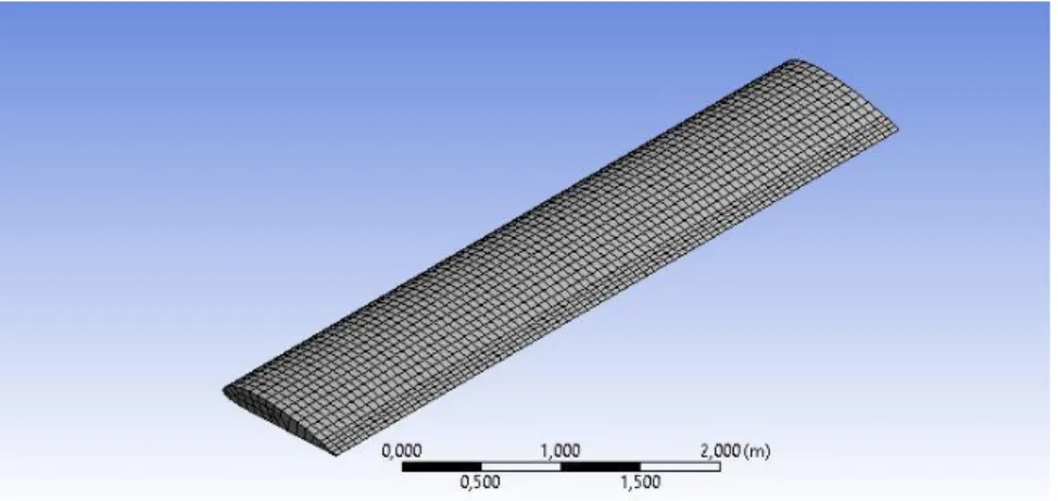
After the wing model was created in SolidWorks (Figure 3), it was treated as cantilevered beam which was fixed at one end and free at the other end.
Figure 3. The model of the wing.
The total number of nodes generated in the meshing of the test structure is 16202, and the total number of elements is found to be 2890. The mesh structure was presented in Figure 4.
Figure 4. The obtained modes of the wing
The modal analyses were performed by using ANSYS and the obtained modes of the wing were presented in Figure 5. The related frequencies were also given in Table 4.(Torsional modes and frequencies were ignored).
a) 1
stmode
b) 2
ndmode
c) 3
rdmode
d) 4
thmode
Figure 5. The obtained modes & mode shapes of the wing Table 4. Natural frequency results of numerical modal analysis.
Natural Frequency Modes Frequency (Hz) 1 4,2446 2 26,374 3 72,916 4 140,23 5 226,03 6 326,32
COMPARISON OF RESULTS AND DISCUSSION
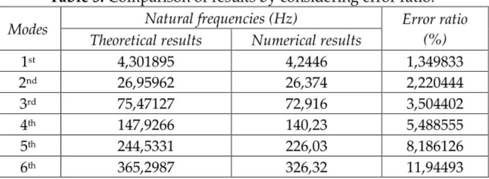
In this section, results of numerical modal analyses and analytical method are compared. The obtained natural frequencies of both analysis (modal and theoretical) are presented in Table 5 and plotted in Figure 6. As it can be seen there are a good agreement between two methods at the first mode. As the mode number increases the error ratio between numerical and theoretical methods increases. These errors may have been caused by the empirical formulas (Eq.11 and Eq.12) and the meshing quality that affects greatly a FEA results.
Table 5. Comparison of results by considering error ratio.
Modes Natural frequencies (Hz) Error ratio
(%) Theoretical results Numerical results
1st 4,301895 4,2446 1,349833 2nd 26,95962 26,374 2,220444 3rd 75,47127 72,916 3,504402 4th 147,9266 140,23 5,488555 5th 244,5331 226,03 8,186126 6th 365,2987 326,32 11,94493
Figure 6. Comparative curves of cantilever beam frequency. CONCLUSION
In this study, the wings of aircraft was considered as a cantilever beam in order to perform modal analysis. The results of numerical modal analysis and theoretical approach method of cantilever beam were compared. It was seen that natural frequency obtained from numerical and theoretical approaches are in good agreement. The validation of modal analysis of cantilever beam proved that the procedure opted for numerical modal analysis of aircraft wing and its result are correct.
SYMBOLS
ωn: Natural Frequency [rad/sec]
fn: Natural Frequency [Hz]
βn: Natural Angle [rad]
L: Length [m]
E: Young Modulus [Pa] I: Moment of Inertia [kg/m-2]
m: Mass per length [kg/m] A: Area [m2]
Yu(x): Maximum Y(x) value of The Wing [m]
Yl(x): Minimum Y(x) value of The Wing [m]
𝑦̅: Average value of Yu and Yl [m]
KA: Proportionality coefficient of Area
KI: Proportionality coefficient of Moment of Inertia
t: Maximum Thickness of The Wing [m] h: Maximum Camber of The Wing [m] c: Chord Length of The Wing [m] REFERENCES
Airfoil Tools, http://www.airfoildata.com, visit date: August 23, 2017
Amarendra K., Rapuri, A.K., 2016, Dynamic Analysis of A Wind Turbine Blade, Advanced Research
Journals of Science and Technology (ARJST), 134-139
0 50 100 150 200 250 300 350 400 0 1 2 3 4 5 6
N
atur
al
fr
e
q
u
e
n
cy
[
Hz
]
Mode number
Theoretical results Numerical resultsBagul A. D., Barijibhe R. B. and Patil A. V., 2014, Vibrational Analysis of Gearbox Casing Component using FEA Tool ANSYS and FFT Analyser, International Journal of Engineering Research &
Technology (IJERT), Vol. 3 Issue 2.
Carrera E.., Marco Petrolo M.., Varello, A., 2012, Advanced Beam Formulations for Free-Vibration Analysis of Conventional and Joined Wings, J. Aerosp. Eng., 25(2), 282-293, 2012.
Erdener. Ö. and Yaman. Y., 2003, Bir Uçak Kanadının Yapısal Modelinin Geliştirilmesi, Ulusal Makine
Teorisi Sempozyumu (UMTS).
Ewins, D.J., 2000, Modal Testing: Theory, Practice and Application. England: Wiley, Second Edition
Gupta, R.S. and Rao, S.S.,1978, Finite Element Eigenvalue Analysis of Tapered and Twisted Timoshenko Beams. Journal of Sound and Vibration 56(2), pp 187- 200.
Jaworski, J.W.and Dowell, E.H., (2008), Free vibration of a cantilevered beam with multiple steps: Comparison of several theoretical methods with experiment, Journal of Sound and Vibration Vol. 312, Issues 4–5, pp 713-725
Kacar, A., Tan, H.T. and Kaya, M.O., 2011. Free Vibration Analysis Of Beams On Variable Winkler Elastic Foundation By Using The Differential Transform Method, Mathematical and
Computational Applications, Vol. 16, No. 3, pp. 773-783.
Khadse, N.A. and Zaweri, S.R., 2015, Modal Analysis of Aircraft Wing using Ansys Workbench Software Package, International Journal of Engineering Research & Technology (IJERT), ISSN: 2278-0181, IJERTV4IS070291, Vol. 4, Issue 7.
Lengvarský, P., Bocko, J., Hagara, M., 2013, Modal Analysis of Titan Cantilever Beam Using ANSYS and SolidWorks, American Journal of Mechanical Engineering, Vol. 1, No. 7, 271-275.
MIT OpenCourseWare, http://ocw.mit.edu/courses/aeronautics-and-astronautics/16-01-unified-engineering-i-ii-iii-iv-fall-2005-spring-2006/systems-labs-06/spl10b.pdf, visit date: August 23, 2017
MatWeb ASM Aeurospace Specification Metals
http://asm.matweb.com/search/SpecificMaterial.asp?bassnum=ma6061t6, visit date: November 6, 2017
Nirmall, T. and Vimala, S., (2016). Free Vibration Analysis of Cantilever Beam of Different Materials,
International Journal of Applied Engineering Research ISSN 0973-4562 Volume 11, Number 9, pp
6521-6524.
Ozturk, B. and Coskun, S.B., 2013, Analytical Solution for Free Vibration Analysis of Beam on Elastic Foundation with Different Support Conditions, Mathematical Problems in Engineering Volume http://dx.doi.org/10.1155/2013/470927.
Rajappan, R. and Pugazhenthi, V. , 2013, Finite Element Analysis of Aircraft Wing Using Composite Structure, The International Journal of Engineering And Science (IJES), Volume2, Issue 2, Pages 74-80 ISSN: 2319 – 1813 ISBN: 2319 – 174-805.
Rao, S.S. , 2011, Mechanical Vibrations, 5th Edition, Pearson.
Thambiratnamt, D. and Zhuge, Y., 1996. Free Vibration Analysis of Beams on Elastic Foundation,