Preparation of Al2O3 and AlN Nanotubes by Atomic Layer Deposition
Cagla Ozgit1, Fatma Kayaci1, Inci Donmez1, Engin Cagatay1, Tamer Uyar1, and Necmi Biyikli1
1
UNAM – Institute of Materials Science and Nanotechnology, Bilkent University, Ankara 06800, Turkey.
ABSTRACT
Al2O3 and AlN nanotubes were fabricated by depositing conformal thin films via atomic
layer deposition (ALD) on electrospun nylon 66 (PA66) nanofiber templates. Depositions were carried out at 200°C, using trimethylaluminum (TMAl), water (H2O), and ammonia (NH3) as the
aluminum, oxygen, and nitrogen precursors, respectively. Deposition rates of Al2O3 and AlN at
this temperature were ~1.05 and 0.86 Å/cycle. After the depositions, Al2O3- and AlN-coated
nanofibers were calcinated at 500°C for 2 h in order to remove organic components. Nanotubes were characterized by using X-ray photoelectron spectroscopy (XPS), scanning electron
microscopy (SEM), and transmission electron microscopy (TEM). AlN nanotubes were polycrystalline as determined by high resolution TEM (HR-TEM) and selected area electron diffraction (SAED). TEM images of all the samples reported in this study indicated uniform wall thicknesses.
INTRODUCTION
Atomic layer deposition (ALD) is a special type of low-temperature chemical vapor deposition, in which the substrate is exposed to sequential pulses of two or more precursors separated by purging periods [1]. Unless decomposition of the precursor occurs, each pulse leads to surface reactions that terminate after the adsorption of a single monolayer. Film growth mechanism of ALD is therefore self-limiting, which gives rise to unique properties such as high uniformity and conformality, as well as sub-nanometer thickness control.
In 2007, Peng et al. [2] combined ALD with electrospinning in order to fabricate long and uniform metal-oxide microtubes with precise wall thickness control. In their study, Al2O3 was
deposited on electrospun poly(vinyl alcohol) microfibers, which were then removed by
calcination. This approach was followed by other researchers, who synthesized tubes of various sizes, materials (Al2O3 [3,4], TiO2 [5,6], ZnO [3,4,7-9]), and structures (e.g. core-shell
nanofibers) using different electrospun templates (nylon-6 [4], poly(vinyl acetate) [7-9], poly(vinyl alcohol) [3], poly(vinyl pyrrolidone) [5,6]).
Here we report on the fabrication of Al2O3 and AlN nanotubes by depositing conformal thin
films via ALD on electrospun nylon 66 nanofiber templates. Chemical composition and bonding states of the nanotubes were investigated by XPS, whereas structural characterization was carried out by electron microscopy and diffraction.
EXPERIMENTAL DETAILS
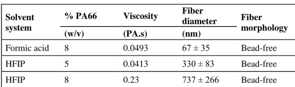
Nylon 66 (PA66) nanofiber templates were prepared by electrospinning of formic acid and hexafluoroisopropanol (HFIP) solutions. Different polymer concentrations were used according to solvent systems in order to obtain nanofibers having different diameters (see table I). For all the polymer solutions studied; feed rate, applied voltage and tip-to-collector distance were 1 ml/h, 15 kV and 10 cm, respectively. Morphology, uniformity, and dimensions of electrospun nanofibers were studied by using scanning electron microscopy (SEM).
Al2O3 and AlN depositions were carried out at 200°C in Savannah S100 and Fiji F200-LL
ALD reactors (Cambridge Nanotech), respectively. Deposition rates of Al2O3 and AlN at this
temperature were ~1.05 and 0.86 Å/cycle. 300 cycles of Al2O3 were deposited using
trimethylaluminum (TMAl) and H2O as the aluminum and oxygen precursors, respectively. N2
was used as the carrier gas with a flow rate of 20 sccm. After the deposition, alumina-coated nanofibers were calcinated at 500°C for 2 h under atmospheric conditions in order to remove the organic component. 300 and 800 cycles of AlN were deposited via plasma-enhanced ALD (PEALD) using TMAl and ammonia (NH3). NH3 flow rate and plasma power were 50 sccm and
300 W, respectively. Ar was used as the carrier gas with a flow rate of 60 sccm. In-situ calcination of the AlN-coated nanofibers was performed at 500°C for 2 h.
Chemical composition and bonding states of the AlN nanotubes were determined by X-ray photoelectron spectroscopy (XPS) using Thermo Scientific K-Alpha spectrometer with a monochromatized Al Kα X-ray source. Electron microscopy studies were carried out by using FEI Quanta 200 FEG scanning electron and FEI Tecnai G2 F30 transmission electron
microscopes.
Table I. Properties of PA66 solutions and the resulting electrospun nanofibers. Solvent
system
% PA66 Viscosity Fiber
diameter Fiber
morphology
(w/v) (PA.s) (nm)
Formic acid 8 0.0493 67 ± 35 Bead-free
HFIP 5 0.0413 330 ± 83 Bead-free
HFIP 8 0.23 737 ± 266 Bead-free
DISCUSSION
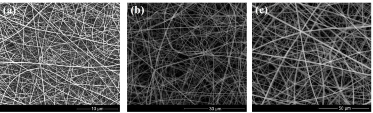
SEM images of electrospun PA66 nanofiber templates are given in figure 1. Electrospinning of 8% formic acid solution resulted with an average fiber diameter of ~70 nm, whereas 5 and 8% hexafluoroisopropanol (HFIP) solutions produced fibers having average fiber diameters of ~330 and ~740 nm.
By controlling the electrospinning and ALD process parameters, Al2O3 and AlN nanotubes
having different diameters and wall thicknesses were fabricated. SEM image of ~740 nm diameter PA66 nanofiber template after deposition of 300 cycles Al2O3 is given in figure 2(a).
uniform and conformal alumina layer on electrospun PA66 nanofibers. Integrity of this conformal layer was retained even after the calcination of organic fibers (see figure 2(b)). A similar approach was also applied for the fabrication of AlN nanotubes (see figures 2(c) and (d)).
Figure 1. SEM images of electrospun PA66 nanofibers templates having (a) ~70, (b) ~330, and (c) ~740 nm average fiber diameter.
Figure 2. SEM images of Al2O3-coated PA66 nanofibers before (a), and after (b) ex-situ
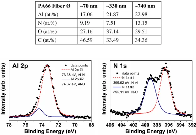
Chemical composition and bonding states of the AlN nanotubes were investigated by using X-ray photoelectron spectroscopy (XPS). Survey scans detected peaks of Al, N, O, and C (see table II). Carbon and oxygen contents of nanotubes were high, indicating the presence of residual organic components. Formation of AlN was confirmed by Al 2p and N 1s high resolution XPS scans, which are given in figure 3. Al 2p scan was fitted by two subpeaks located at 73.38 and 74.37 eV, corresponding to Al-N [10,11] and Al-O [12] bonds, respectively. N 1s high resolution scan was also fitted by two subpeaks. The peak located at 396.62 eV was attributed to the N-Al bond [12,13]; whereas the one located at 399.11 eV was assigned as the N-O bond [13].
Table II. XPS survey scan results.
PA66 Fiber Ø ~70 nm ~330 nm ~740 nm Al (at.%) 17.06 21.87 22.98 N (at.%) 9.19 7.51 13.15 O (at.%) 27.16 37.14 29.51 C (at.%) 46.59 33.49 34.36
Figure 3. (a) Al 2p, and (b) N 1s high resolution XPS scans of AlN nanotubes fabricated by using ~740 nm diameter PA66 nanofibers.
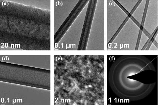
TEM images of AlN nanotubes fabricated by depositing 800 cycles AlN on PA66 nanofiber templates are given in figures 4(a-d). For all the samples, wall thicknesses were found to be highly uniform. This indicates that precise wall thickness control is possible simply by adjusting the number of ALD cycles. Crystal structure of the AlN film deposited on polymeric templates was studied by high resolution TEM (HR-TEM) and electron diffraction. HR-TEM image of an AlN nanotube fabricated by using ~330 nm diameter PA66 nanofibers is given in figure 4(e). AlN was found to be polycrystalline with nanometer sized grains. This was further confirmed by selected area electron diffraction (SAED). SAED pattern of the same sample (see figure 4(f)) revealed several polycrystalline diffraction rings.
Figure 4. TEM images of AlN nanotubes fabricated by using ~70 (a-c), and ~330 nm (d) diameter PA66 nanofibers. HR-TEM image (e) and SAED pattern (f) of AlN nanotubes fabricated by using ~330 nm diameter PA66 nanofibers.
CONCLUSIONS
Al2O3 and AlN nanotubes were fabricated by depositing conformal thin films on electrospun
PA66 nanofiber templates. Depositions were carried out at 200°C, using thermal and plasma-enhanced ALD processes with deposition rates of ~1.05 and 0.86 Å/cycle for Al2O3 and AlN,
respectively. After the depositions, coated nanofibers were calcinated at 500°C for 2 h in order to remove organic components. XPS survey scans detected high contents of carbon and oxygen in the AlN nanotubes, which was attributed to the presence of residual organic components. Formation of AlN was confirmed by high resolution XPS peaks located at 74.37 (Al 2p) and 396.62 eV (N 1s). TEM images of the samples indicated uniform wall thicknesses. AlN films deposited on polymeric fibers were polycrystalline as determined by high resolution TEM (HR-TEM) and selected area electron diffraction (SAED).
ACKNOWLEDGMENTS
This work was performed at UNAM supported by the State Planning Organization (DPT) of Turkey through the National Nanotechnology Research Center Project. N.B. acknowledges support from Marie Curie International Re-integration Grant (Grant # PIRG05-GA-2009-249196).
REFERENCES
1. M. Ritala and M. Leskelä, in Handbook of Thin Film Materials Vol. 1, edited by H. S. Nalwa (Academic Press, San Diego, 2002) p.103.
2. Q. Peng, X.-Y. Sun, J.C. Spagnola, G.K. Hyde, R.J. Spontak and G.N. Parsons, Nano Lett. 7 (3), 719 (2007).
3. Q. Peng, X.-Y. Sun, J.C. Spagnola, C. Saquing, S.A. Khan, R.J. Spontak and G.N. Parsons,
ACS Nano 3 (3) 546 (2009).
4. C.J. Oldham, B. Gong, J.C. Spagnola, J.S. Jur, K.J. Senecal, T.A. Godfrey and G.N. Parsons, J. Electrochem. Soc. 158 (9), D549 (2011).
5. G.-M. Kim, S.-M. Lee, G.H. Michler, H. Roggendorf, U. Gösele and M. Knez, Chem.
Mater. 20, 3085 (2008).
6. E. Santala, M. Kemell, M. Leskelä and M.Ritala, Nanotechnology 20, 035602 (2009). 7. J.Y. Park, S.-W. Choi, J.-W. Lee, C. Lee and S.S. Kim, J. Am. Ceram. Soc. 92 (11), 2551
(2009).
8. S.-W. Choi, J.Y. Park and S.S. Kim, Nanotechnology 20, 465603 (2009). 9. J.Y. Park, S.-W. Choi and S.S. Kim, Nanotechnology 21, 475601 (2010).
10. N. Duez, B. Mutel, O. Dessaux, P. Goudmand and J. Grimblot, Surf. Coat. Tech. 125, 79 (2000).
11. D. Manova, V. Dimitrova, W. Fukarek and D. Karpuzov, Surf. Coat. Tech. 106, 205 (1998). 12. L. Rosenberger, R. Baird, E. McCullen, G. Auner and G. Shreve, Surf. Interface Anal. 40,
1254 (2008).
13. H.M. Liao, R.N.S. Sodhi and T.W. Coyle, J. Vac. Sci. Technol. A 11(5), 2681 (1993).
View publication stats View publication stats