273
Continuous Processing of Images
through User Sketched Functional Blocks
Aydm Kaya, Biilent 6zgu~·
1. Introduction
The history of image processing is relatively recent compared to other fields but it has been applied to practically every
type
of imagery with varying degree of success, some of which are electronics, photography, pattern recognition and medicine. Several factors encourage the future of image processing further. A major factor is the declining cost of computer hardware and the increasing availability of digitizing equipment (e.g. a TV camera interfaced to a computer)l. As a result it is now easy to store an image in digitized form. Another factor, promoting image processing, is the availability of better display devices and low-cost but large main memories.Images in their natural form are pictorial that is they cannot be processed by the computer directly unless they are transformed into numeric or discrete data. Therefore an image should first be converted into numerical form. This conversion process is called digiti-zation and it generates an image in the form of a col-lection of dots, called picture elements or pixels. In a colour system the value of each pixel (usually between 0 and 255) is an index to a special table, which is called the colour map look-up table. The entry of the colour map table, corresponding to a particular index contains three values and these values are in fact the intensities of three major colours, namely red, green and blue. In a gray scale device, the same idea of referencing a table could be used or the value of a pixel could be treated as an intensity. In an image the combination of all pix-els form a rectangular grid or a 2-dimensional array, therefore any pixel can be addressed by specifying its address in terms of a row number and column number.
After an image is represented in numeric form, now it is possible to process it that is, a series of opera-tions can be applied to it to obtain different forms of the
original
image. The operations to be applied to animage
are classified according to the way that the value of output pixels are obtained. If an operation generates an output pixel whose value is obtained by using only• Depart.ment of Computer Engineering and Information Sciences
Bilkent University
Ankara Turkey
North-Holland
Computer Graphics Forum 7 ( 1988) 273-280
its previous value, this is called a point operation. A locaJ operation is the one in which the value of a pixel is changed according to its old value and the values of neighbouring pixels; this operation is sometimes called an area process. A global operation is the one in which all pixels of the image are treated in the same way. When the positions or arrangemenet of the pixels are changed this operation is called a geometric process.
An operation changing the value of a pixel by compar-ing two or more images is called a frame process2-4. Some of these operations are going to be used as pic-torial examples when the interface is being discussed.
2. The
User
InterfaceThe part of a system that controls the communications between the system and the user is often called the user interface. With the introduction of highly sophisticated, multi-tasking, multi-window personal computers and workstations, the science of user interface design gained a special momentum. It is of great importance to pay careful attention to the design of interactive user inter-faces. A very sophisticated, fully functional software system can be totally invalidated because of poor user interfaces even in the hands of an experienced user, let alone a noviceS· 6.
It is rather ironic that a new common data type, digitized pictures, is mostly processed through com-mand language
type
or keyword menu type interfaces in the majority of image processing software available today. The nature of the data is pictorial and the algo-rithms ~pplied to it usually follow sequences or paths resembling a network, or maybe a logic diagram. It then follows as a natural argument that a user dealing with an image processing application, should interact wi.th the s~stem among these lines. The basic scope of this paper IS to explore such methods of interaction andsuggest ways of software development for image pro-cessing applications.
Our aim is to implement an image processing sys-tem with the previously defined algorithms through the. use of functional blocks connected together to form a diagram that we call a schematic. A functional block means the representation of a routine or function by a visual object in our intent. The arc connecting two blocks is the path and direction through which an image is transferred. In the development of the system
274 A. Kaya et al. I Continuous Processing oflmoges
we relied on the usage of some new developments in
software sciences providing for the construction of better interfaces. Most important of these are the object oriented style of programming,. iconic interfacing, mul-tiple window and multi-tasking operating systems. Even though the intention of this paper is not to explain these rather recent developments, it is still useful to give some limited details since the whole system is based on these new ideas.
2.1. Object Oriented User Interface Model
A toolkit based on the SunView·7 window manager is expanded to form our user interface with its menus, windows, panels, many kinds of panel items, and a schematics capture system. As long as there is no need to enter text, the system is used by a pointing device like a mouse. These components have the characteristics
·Sun View is a registered trademark of the Sun Microsystems.
FUNCI10NAL IMAGE PROCESSING APPLIED
BLOCK NAME
of an object in the sense of object oriented program-ming style even if they may be implemented by using an ordinary language like
cs.
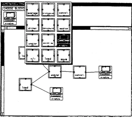
The functional blocks are represented in the form of icons both on the menu that they are chosen from and on the schematic
in
which they act as nodes. Icons are small pictures (usually they are composed by 64 by 64 pixels) and they represent the available image pro-cessing algorithms. The functional block selection menu together with a simple schematic is shown in Fig-ure 1. The image processing algorithms these blocks perform. together with their control variables are given in Table l.Other building blocks of the system are the control panel and the items they contain, sliders and scroU bars, text entry windows and a set of special purpose windows serving as data templates, often referred to as a variable control window, as explained later. It is also important to note here that the term object refers to
CONTROL VARIABLES OR SETTINGS
AVERAGE Enlarges an image by pixel replication or reduces an image by Shrink or Expand pixel averaging
HISTOGRAM Generates a histogram of the current image by counting the none number of times an intensity occurs
CONVOL Enhances edges by replacing pixel's value with the sum of that Size of the convolution kernel. pixel's value and its neighbours by weighting each value by a The contents of the kernel factor (convolution kernel)
DITHER A colour or grayscale image is reduced to be displayed on a none bilevel device by adding an error term to the image intensity
of each pixel before comparing it with a threshold value
THRESHOLD An image is reduced to only a background and foreground Threshold value colour where all values below the threshold are made
back-ground and above are made foreback-ground
MEDIAN Each pixel value is replaced with the middle value of the Size of the neighbour window sorted neighbours
AND/OR Two images are combined in a frame process AND, OR, XOR, PLUS, or DIFFERENCE
POINTOP Point opererations of the contrast and intensity enhancement Contrast enhancement value. Intensity enhancement value DISPLAY Displays the image currently being processed in a window Colour map
+I-
Reserved for another set of frame processes noneLOAD The input process that can be through a camera or a disk file. Filename Currently only a disk file is read
SAVE Output procedure for recording the current image in a file Filename
A. Kaya et a/. I ContiniiOILf Processing of Images 275
Figure I: The Functional Block Selection Menu.
both an entity in the real life, like a picture, and the term "object" in the "object oriented style of prograrn-ming'-9. The difference should be understood from the context. The object classes of the functional blocks and the panel items represent the available choices to the user. The objects have their particular properties and the user tells the system the kind of processing he wants by arranging the icons representing objects of particular functional classes in a network like diagram that we have called schematics. By pointing to the instances of various object classes in the schematics, the properties of object instances could be changed through the data template window that temporarily appears. This particular window is in fact a direct reflection of the object variables for that particular image processing instance. Each instance starts with a default set so it is not necessary to modify these variables that either con-trol the executional variables and constants, or the sub-algorithms to be chosen. In the
case
of instances that are from the class of display devices, the data tem-plate window is the reflection of the image. This is indeed how intermediate images could be displayed, that is, display devices could be linked to internal nodes in the schematics and then their data templates are activated. Other visual object classes are the menus for selection or process control, and the scroll bars for moving images in whichever window they mighthap-pen to be.
In more technical terms, an object is an entity that presents a functional interface. Various details of
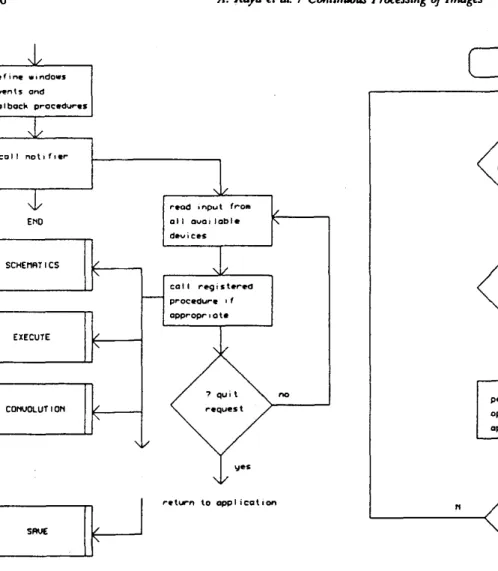
imple-mentation as to how the objects perform their tasks are not exposed to the user. All one has to do is to choose an object, if it belongs to a functional block class instantiate it, and if other than the default values are going to be used, set the instance variables through the data template window. Figure 2 shows the general flow of the interactive system.
When an object is chosen, it calls its associated func-tions in an indirect manner, that is, there is not a predefined sequence of functional calls, but the objects are active processes and are invoked by message pass-ing paradigm when a preregistered event occurs. Fig-ure 2 shows the general flow of the interactive system. There is however a differentiation between a user pro-vided event and a system propro-vided event. If the
user
is dealing with objects belonging to the functional classes directly, his messages are trapped by the schematics editorso
that the schematics could either be con-structed, edited, or the variables of the instances altered (Figure 3).If however, a menu choice for execution is made, user events
are
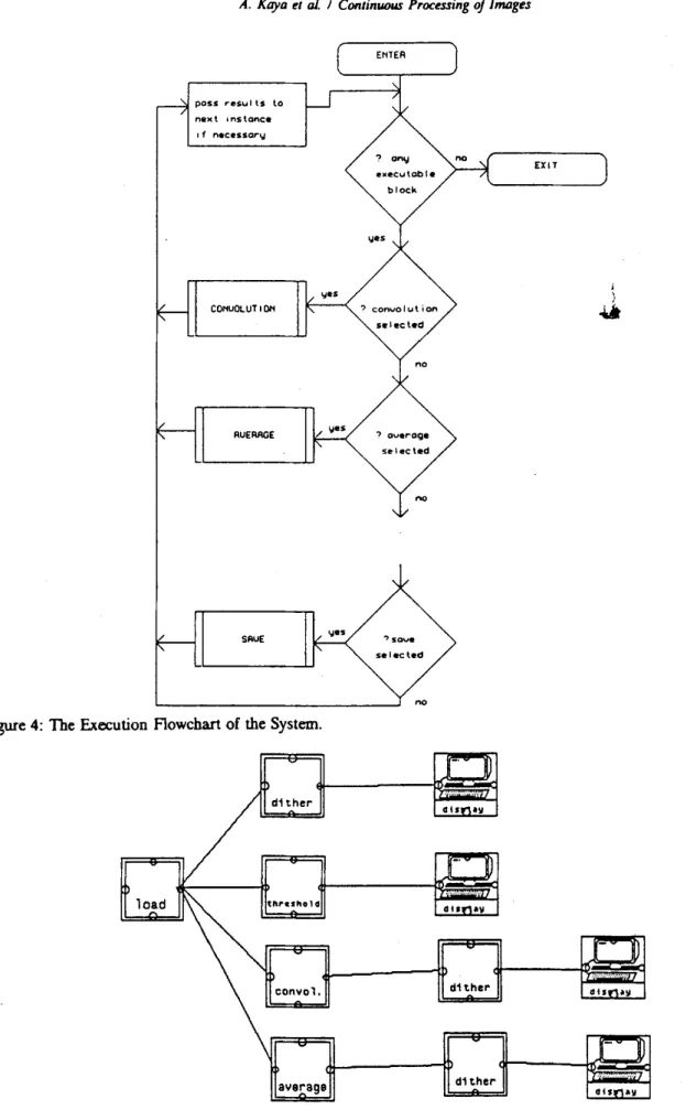
temporarily blocked and each connected instance of a functional block executes its algorithm andpasses
its results to the next one. 1bis is shown inFigure 4. The implementation of the flow and internal message
passing paradigms are
done through linked listslO. There is a simple rule checker that looks for cyclic schematics by the traversal of the list to avoid infinite loops. To notify theuser
of a particular stage,276
A. Kaya ~~ a/. I CorrtiniiOUS Proc~ssing of lmDg~s define wtndows @'v4!'n\s and co I boc~ procedvres call not•f•er-END SCHEMRT ICS EXECUTE CONUOLUT I ONI I
r•od input fro111
all DVOI )able
d•vi~lltS call regish•red proc:.Our-e • f appropr 'o te rehrn to opplicot•on no
Figure 2: The General Flow of the Interactive System.
each functional object class instance notifies the for-matter of the schematics window so that the relevant icon changes its colour when executing.
3. The Functional Blocks IUld Their Use
When a user wants to use an available function or rou-tine it is enough to choose the associated icon of the object from a menu by pointing to it through a mouse. Then the user places the representation of the func-tional block, picked up from the menu, in a drawing window or canvas by attaching it to a mouse button and dragging it to the desired position. When the place-ment is completed, the user can connect the block to another, by pressing a mouse button on a pin of the start block and dragging the mouse until the rubber band line connected to it touches to a pin of the second block. In this case a link between two functional blocks
will be set up both internally (a new instance of the block will be generated and its variables will be set up with the values supplied by either the user or the
sys-N
perforll'l selected operot ion i f
appropriate
Figure 3: The Schematics Flowchart.
se lee t approp,. i o 1.•
operot ion c loss
edit control
J
WindOW
~
tem itself) and externally. An external link in fact is a line between the pins of the functional block represen-tations and it is the responsibility of the user to make the proper appearance of external links. Figure 5 shows a schematic constructed by a user to process an image ..
The user continues in this manner until he forms a .. flowchart-like" schematic and when he believes he has finished the construction he can start the processing by pressing a button in the control panel.
During the construction of the schematic a user can make any changes to the layout of the blocks. For example he can disconnect two blocks, remove a block from the drawing window, etc. Such changes in the schematics cause the necessary refreshing of the win-dow and updates the internal links between the blocks by an automatically generated broadcast message.
A. Kaya et al. I Continuous Processing of Images pos:S ,..e-su I ls lo na)( t 1 ns lance 1 f necessary COr<UOLUT I 01< RUE RAGE SRUE
Figure 4: The Execution Aowchart of the System.
d1ther
~
...
load ~ convol. averageFigure 5: A Schematics to Process an Image.
__
..,.]
dlsf1•v__ ...,.l)
. ... d llf1•Y d1ther d1ther 277 EXIT jJ
r-""""lJ
.;;::;;:.·.··· dlsri•Yr-..-]
.... d1Sf1•Y278
A. Kaya el a/. I ContiliiiOIU Processing of Images lHRESHOLD : 255.1. .,
d1thcr load ROW NlJIIBER ~•
load COLlJIIN NlJII8ER : 3 dtther ~ » -1•
» e » » -1 » e » avaraga » -1 »B » » -1 » e )) 1 )) -1 »B )) 1 averageA. Kayo ~~ of. I Continuou.J Proc~ssing of Images
279
The processing or the execution of the schematics
is the interpretation of the functional blocks and the
internal links between them. Until all the blocks in the schematics are exhausted, the appropriate functions are invoked through a message passing paradigm and the
_necessary parts of the obtained results are passed to the next functional block if one exists.
During the placement of blocks on the canvas (drawing data template window of the schematic
func-Figure 7: The "Orange" has been Dithered .
.
· ... ·: : .. :. .·:· ... .-.... · .. · ·:·.··
••
:H
···
·
·
:
..
~~1'
--u:·:·
.. :·_.· .. ·:·'· ... •. . ·.
.
. . . . - . . _;· . .... ... . .. .···
·
·
~~~
~
·
<>
··· . .. . . ·. ::.:~---··: . . . . . ..
.
:.:-:::::: .-·-.. · .... :. ·.: ~~z;.,:•~-~~-; ... . .Figure 9: The "Orange" has been Convolved to Amplify the Vertical Lines.
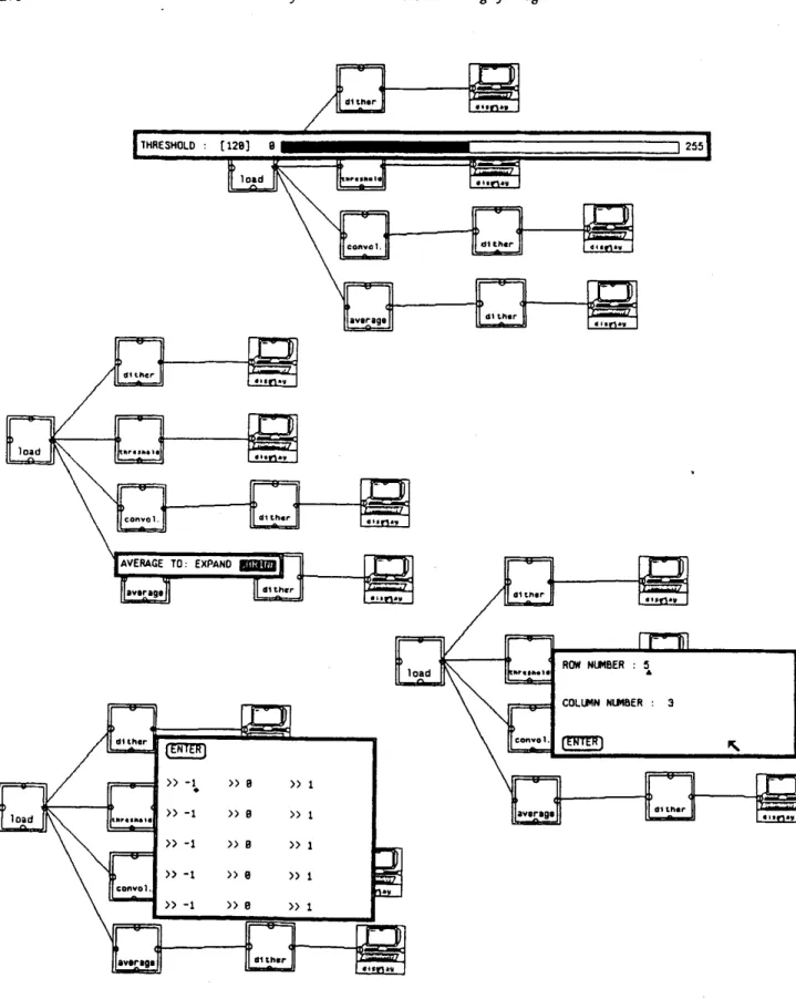
tion) the user is free to change the settings of an object and he does this by pressing a mouse button on the representation of the object on the canvas. In this case a data template window for the selected functional block is opened and the user makes the necessary updates related to the object class instance. Figure 6 shows the usage of data template windows to make changes on the settings of an object instance. Table I shows the values that can be set for the functional
Figure 8: The Threshold of the "Orange ...
280 A. Kaya eta/. I Continuous Processing of Images
block instances. These windows are used, in the exam-ple, to set a threshold value of 120, to set the average to shrink, and to set the convolution kernel size and then enter its values. The results of the four display devices are shown in Figures 7 to 10.
4. Conclusion
The system and style of interface described presents ideas for interacting with image data. Many tools, stan-dards, and methods have been developed for interacting with textual and graphical data. Image data still waits for its share of standards both in data communication and in storage-retrieval techniques and formats, let alone in interaction principles. The approach suggested seems suitable since it represents the actual events tak-ing place durtak-ing image manipulation procedures. This is not much different,
say,
to the insertion of special commands and characters in text formatting.Images displayed in some special device data tem-plate windows can be edited manually by operations such as cut and paste, colour map manipulation, paint-ing, etc. This is an ongoing part of the project.
With new entries to the VLSI market, some image processing functions are implemented in hardware. This increases the speed of many such functions, and perhaps the approach described in this paper could be run in real time where the input device is a CCD cam-era and each functional block is a reference to a chip on a board. Whatever the environment may be. the use of highly interactive and user friendly pictorial interfaces is believed to be a feasible solution in com-puter imaging applications.
References
1. Kenneth R. Castleman, Digital Image Processing,
Prentice Hall Inc., Englewood Cliffs. N.J. (1979). 2. Donald Hearn and M. Pauline Baker, Computer
Graphics, Prentice Hall (1986).
3. David F. Rogers, Procedural Elements For Com-purer Graphics, Me Graw Hill ( 1985).
4. Benjamin M. Dawson, "Introduction to Image Processing Algoritms," BYTE. pp. 169-186 (March 1987).
5. Bi.ilent
Ozguc,
"Thoughts On User Interface Design For Multi Window Environments," pp. 417-488 in Second International Symposium on Computer and Information , Sciences, Istanbul (1987).6. William M. Newman, Robert F. Sproull, Princi-ples of Interactive Computer Graphics, McGraw
Hill ( 1979).
7. Sun Microsystems, Inc., Sun View Programmer's Guide, Mountain View, California, 1986.
8. Owen M. Densmore. David S. H. Rosenthal, "A User-Interface · Toolkit in Object-Oriented POSTSCRIPT," Computer Graphics Forum 6. pp. 171-180 (1987).
9.
0.
M. Nierstrasz, "What Is Object In Object-Oriented Programming," pp. 1-13 in The Proceed-ings of the CERN, Renesse, The Netherlands( 1986).
10. Jonathan P. Jacky and Ira J. Kalet. "An Object-Oriented Programming Discipline For Standard Pascal." Communications of the ACM 30(Y). pp. 772-776 (September 1987).